
by PAUL D CHAPMAN
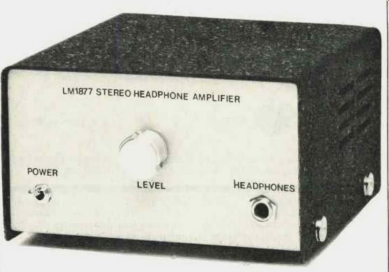
When listening through headphones is desirable, sometimes it isn't possible, either because the component you're listening to lacks a headphone output or because (as with many tape decks) its headphone output doesn't deliver enough signal to power the phones you have. This easy-to-build stereo headphone amp will solve both problems. All parts are available from Radio Shack (except the voltage regulators) for about $35. If you shop around, you can probably cut that price still further.
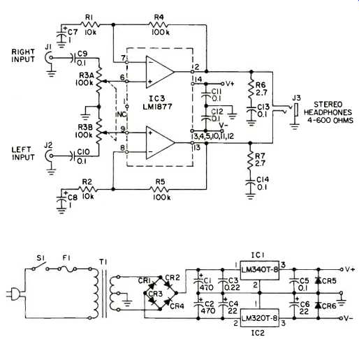
The circuit is quite straightforward. The split power supply minimizes components and eliminates the need for large electrolytic capacitors on the audio output. Voltage regulators are used for clean power without large, expensive filter capacitors. (You can also use two 9-volt batteries in center-tapped series, but their life may be short, the more so with lower impedance headphones.) The power supply is well bypassed, and the 2.7-ohm resistors (R6, R7) and 0.1-µF capacitors (C13, C14) on each output help suppress oscillations. The amplifier's gain of 20 dB is set by the 100-kilohm feedback resistors (R4, R5) and the 10-kilohm resistors (R1, R2) on the inverting inputs.
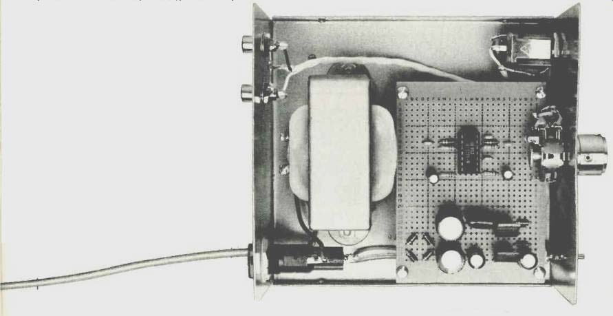
Construction details are left up to the builder. The circuit is too simple to justify a p.c. board; use an experimenter-type perf. board, such as Radio Shack's 276-158. Be sure to place capacitors C3, C4, C5, C6, C11 and C12 as close as possible to their respective ICs, to suppress oscillations.
This simple amplifier should prove satisfying to build and, since its THD is below 0.1%, to listen to.

PARTS LIST
(With Radio Shack part numbers, except where noted)
C1, C2--470µF, 35-V electrolytic capacitors (272-1018).
C3--0.22µF, 50-V, 5% mylar capacitor (272-1070).
C4, C6--22µF, 35-V electrolytic capacitors (272-1014).
C7, C8--1µF, 16-V electrolytic capacitors (272-1419).
C5,C9, C10, C11, C12, C13, C14--0.1 µF ceramic disc capacitors (272-131).
CR1, CR2, CR3, CR4, CR5, CR6-1N4002, 200-PIV, 1-A diodes (276-1102).
F1--1-A fuse (270-1273).
IC1-LM340T-8, +8 V regulator (Jameco, 1355 Shoreway Rd., Belmont Cal. 94022).
IC2-LM320T-8,-8 V regulator (Jameco), IC3-LM1877 stereo amplifier (276-702).
J1, J2--Phono jacks (274-346).
J3-3--conductor headphone jack, quarter-inch (274-282) or 3.5 mm (274-249).
R1, R2--10-kilohm, 1/8-W, 10% resistors (271-1335 or 271-034).
R3--100-kilohm, audio-taper, stereo volume control (275-1732).
R4, R5 100-kilohm, 1/8-W, 20% resistors (271-1347 or 271-045).
R6, R7-2.7- or 3.3-ohm, 1-W resistors (271-075).
S1--SPST toggle switch (275-602 or similar).
T1--18 to 36 V, CT transformer, 450-mA or greater (270-1366).
Perf. Board--2 3/4 x 3 3/4 in. (276-158).
Fuse-Holder--(270-364).
Cabinet--Approx. 3 x 5 x 5 in. (270-253).
Misc. Hardware--One knob, screws, nuts, washers, lock-washers, four circuit-board standoffs, one power cord.
(Source: Audio magazine, May 1983)
Also see:
Headphones around the house (May 1974)
Headphones: History and Measurement (May 1978)
A History of Binaural Sound (Mar. 1986)
How to Build a Low Cost Stereo Enhancer (May 1983)
Battle of the Amps (Jun. 1983)
= = = =