By LEONARD FELDMAN
How often in the last month have you felt like switching your FM tuner or receiver from stereo to mono reception be cause the noise and distortion accompanying the desired program were in tolerable? If, like me, you crave good FM reception, you've probably been frustrated more than once by the seriously degraded signal quality of stereo FM compared to mono reception. In fringe-area listening locations, the difference in signal-to-noise ratio be tween a station's mono and stereo signals can be as great as 23 dB! If you've been troubled by this disparity between mono and stereo reception, imagine how the broadcaster feels. An FM station's potential audience for stereo may be only one-third to one-fourth as great as it is for mono.
Of course, when you are bothered by noisy stereo reception, you usually have the option of switching over to mono-but if you are like me, more often than not you will simply tune to another station that's closer, for quieter stereo.
In 1961, when the FCC approved the present system for stereo FM broad casting, they were well aware of that system's signal-to-noise degradation. At that time, however, they seemed more interested in preserving existing reception quality for the mono listener than in safeguarding the stereo listener's interests. (Of course, there were no stereo listeners at the time.) An al ternate system that might have provided virtually no signal-to-noise degradation in stereo would have introduced an S/N loss of around 6 dB for some mono listeners, so the FCC chose to favor the 17 million or so owners of mono FM radios. The millions who subsequently purchased stereo FM sets (whether for car, home, or portable use) have been suffering ever since.

Making Stereo as Quiet as Mono
A system of stereo FM transmission, dubbed FMX, developed jointly by Emil Torick of the CBS Technology Center and Tom Keller of the National Association of Broadcasters (NAB), could well rectify this situation if adopted by FM stations around the country. What makes the system particularly at tractive is that it is completely compatible with existing FM radios and tuners. Owners of such equipment would continue to get the same kind of stereo (or mono) FM that they've been getting. Purchasers of new, specially designed tuners or receivers, on the other hand, would enjoy noise-free reception even of stereo stations that were previously too noisy to listen to without switching to mono.
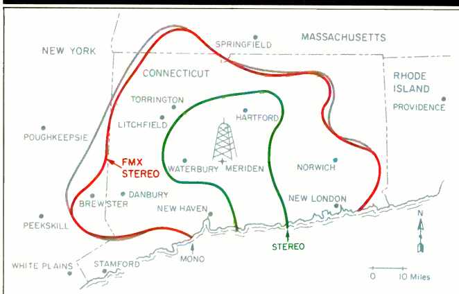
Fig. 1--Reception contours for a station using FMX, showing distance limits
at which tuners could achieve 60-dB S/N in mono, FMX stereo, and conventional
stereo. Note that quiet stereo reception with FMX extends nearly as far
as quiet mono reception.
Another nice thing about the FMX system is that FM stations can adopt it without requesting the FCC's approval. That's because the FCC has liberalized its rules regarding the use of sub-carriers by FM stations. Since the FMX system involves the use of subcarriers within the frequency baseband authorized by the FCC, stations could begin using the system at once. Public radio station WPKT-FM in Meriden, Connecticut has been using the new system experimentally for some time, and field tests show that this station's effective stereo coverage using FMX has in creased to just about the same as its mono coverage (Fig. 1).
How FMX Works
Figure 2 shows the baseband format of the new composite signal which modulates the station's carrier. The portions of this signal which are upright in the figure are identical to those of standard, non-FMX stereo FM trans missions. A monophonic, left-plus-right (L + R) sum signal, labeled M in the diagram, extends from 50 Hz to 15 kHz. Above it is a subcarrier signal, labeled S, consisting of sidebands ex tending 15 kHz above and below the subcarrier center frequency of 38 kHz. The sidebands are due to modulation by the L- R difference signal; the subcarrier itself is suppressed, but a 19-kHz pilot signal (labeled P) is used by the receiver to re-create the 38-kHz subcarrier and to trigger a tuner's or receiver's "Stereo" light.
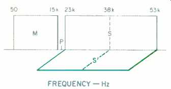
Fig. 2--The FMX composite signal, showing conventional mono sum (M) and
stereo difference (S) components, plus the new FMX sideband (S') 90°
out of phase with the other components. Note the pilot signal (P) at
19 kHz.
The FMX system leaves the standard pilot, sum, and difference-modulated subcarrier signals unaltered but adds a second, difference-modulated sub-carrier (labeled S') in quadrature (i.e., 903 out of phase) with the first subcarrier. Thus displaced in phase, it will not be detected by ordinary FM receivers or tuners.
The second subcarrier (S') is part of a companding noise-reduction system. Most of the noise that is so bothersome when we listen to stereo FM comes from the recovered difference (L- R) signal, not from the main-channel signal. So, if there were some way to intro duce an effective companding or noise-reduction technique to this difference signal, the overall signal-to noise ratio of received stereo FM could be significantly improved. In companding noise-reduction systems, a compressor boosts low-level signals to get them up and over the transmission or recording medium's inherent noise. At the receiving end, the program is restored to its original dynamic range by an expander, which lowers those previously boosted levels and thus lowers the medium's background noise as well.
There is an almost limitless number of ways in which companding can be accomplished for audio applications. Dolby B noise reduction, for example, compresses and expands only high frequencies, since that's where tape hiss is most audible. Dolby C NR extends this action down to somewhat lower frequencies, and also uses more compression and expansion than Dolby B. Both Dolby NR systems work only on low-level signals, leaving high level signals unaltered, and are there fore referred to as nonlinear companding systems.
The dbx noise-reduction system, on the other hand, compands all audio frequencies, and compresses all signal levels linearly, by a factor of 2:1. That is, every 2 dB of level change in an audio signal is compressed to a 1-dB change before it is recorded onto tape. During playback, dbx NR expands all frequencies, so that a 1-dB change in the level of the playback signal is expanded to a 2-dB change in output.
The compression technique chosen for the FMX system has several unique aspects. It is called a re-entrant compression system because it has a threshold above which no action takes place. It is configured to keep the sum of the S and compressed S' signals from over-modulating the transmitter at high signal levels, and to provide optimum channel loading or utilization at mid-levels with a compression slope that's close to infinite.
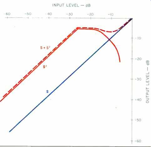
Fig. 3--Characteristics of the re-entrant compressor used for FMX transmission.
Figure 3 shows the response of the compressor S' (upper solid line), the uncompressed S channel (lower solid line), and the combination of the two signals (dashed line), which represents the total subcarrier burden imposed on the main carrier. At low signal levels, the compressor acts like a simple gain stage, raising the level of the S' signal about 20 dB above that of the uncompressed (S) subchannel. At medium input levels, the compression characteristic actually exhibits a slightly negative slope, and at still higher levels it becomes a rapidly changing negative slope. Figure 4 is a block diagram which illustrates the basic concept of the transmission system.
An Adaptive Expander
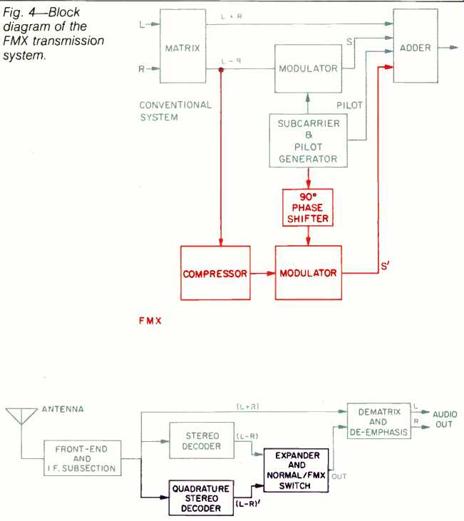
(top) Fig. 4--Block
diagram of the FMX transmission system. (above) Fig. 5--Block diagram of
an FMX receiver.
Though this type of compression system can be shown to make the most of available transmitter power and modulation characteristics, such compression cannot be decoded by a traditional expander having fixed slopes or expansion ratios. Perhaps the cleverest scheme of the entire system is the one used to re-expand the compressed L-R information.
Figure 5 is a block diagram of an FM tuner equipped to receive and decode the new FMX transmissions. A selector switch is included so that a listener may choose either companded FMX or conventional stereo FM reception.
Note that even in its FMX mode, the tuner also detects the standard, conventional subcarrier. This subcarrier may include undesirably high levels of background noise, but its audio pro gram content accurately conveys the instantaneous amplitudes of the L-R signal. So, while we don't want to listen to the audio information carried by this noisy subcarrier, the expander circuit can use that audio information as a reference signal--one that will provide the information the expander needs to restore the audio retrieved from the new quadrature-related S' subcarrier to precisely the same correct levels. This is important because the restored L-R amplitudes must correspond exactly to what they were in the original program, or else incorrect de-matrixing of the L + R and L-R signals will take place. That, in turn, would reduce stereo separation severely.
Figure 6 shows one possible arrangement for an adaptive expander.
The conventional difference signal (S) is rectified and applied to one input of a comparator circuit. This signal acts as the reference signal in a feedback path. The compressed difference signal (S') is fed to a voltage-controlled, variable-gain amplifier whose output is detected in a rectifier and applied to the other input of the comparator stage. The comparator's output, smoothed by appropriate attack and release time-constant circuits, is used to regulate the voltage-controlled, vari able-gain amplifier's gain.
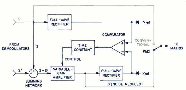
Fig. 6--Block diagram of an adaptive expander section for an FMX tuner.
Whenever a difference exists between the level of the expanded signal and the unmodified S signal, the comparator will produce a control signal which causes the gain of the voltage-controlled, variable-gain amplifier to change until the comparator's output voltage approaches zero. As a result, the magnitude of the compressed difference signal becomes virtually equal to the level of the conventional difference signal. In this way, the expanded signal "tracks" the conventional signal and is totally independent of the absolute value of the compressed signal.
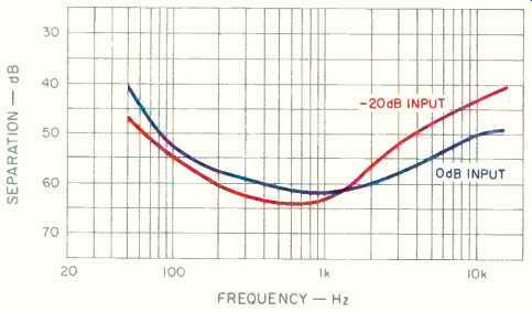
Fig. 7--Separation measured by the CBS Technology Center for an FMX decoder shows
high mid-band separation at two signal levels.
Figure 7 illustrates the separation measured by the engineers at the CBS Technology Center for an actual de coder using this adaptive expander approach. Notice that mid-band separation figures as high as 60 dB were measured in these closed-circuit tests. Even conventional decoders of regular FM stereo rarely are able to achieve such high stereo separation.
One additional refinement has been added to the FMX system recently. That is a low-level, sub-audible 10-Hz signal which is transmitted along with the quadrature subcarrier signal (S'). This additional signal provides switching information for FMX receivers and tuners, and may possibly also be used as an indicator-light cue so that listeners know when a station is, in fact, using the FMX transmission system.
Listeners to the station (WPKT) which has been testing FMX are evidently not aware that anything is different. There have been no complaints about any change in signal quality of the conventional FM or stereo FM transmissions.
The idea of companding as a means of reducing noise generated by a transmission system had not even been thought of when the FCC first authorized stereo FM back in the early 1960s. Twenty years later, when the TV industry was considering different systems for stereo TV sound, the need for companding was realized almost immediately. The system selected for stereo TV includes a companding approach (in this case, one developed by dbx). CBS was also a proponent of a companding system for stereo TV. The FMX idea grew out of that technically related effort.
Since the CBS Technology Center introduced FMX at a professional engineering conference, many FM broad casters have expressed interest. One manufacturer, NAD, has shown a prototype of a tuner using discrete-component FMX circuitry. But even before that, some IC manufacturers had shown an interest in tooling up to produce FMX decoder chips. As with all such new inventions, there is always the question of who is going to make the first move. In order to interest FM stations in the idea, assurances must be given that there will be receivers out there to pick up the improved FM stereo signal. And in order to interest receiver manufacturers in building components with FMX decoding capability, there has to be a promise of IC avail ability so that costs of hardware implementation don't become particularly excessive.
One thing you can do to help spread the use of the new FM system is to make your favorite FM stations aware of its existence. Once they know there is a way to triple or quadruple their useful stereo listening area, they'll probably be eager to learn more about the system. You can refer them to this article or, better still, have them call the CBS Technology Center in Stamford, Connecticut. In case you are an FM station engineer or manager and want to call, the number is (203) 327-2000. Maybe it's not too late to rectify a 25-year-old mistake, after all.
(adapted from Audio magazine, May 1986)
Also see:
The Problem with FM (March 1985)
Antennas FM -- Try a Rhombic FM Antenna (Jan. 1982)
MUSIC ON THE MOVE: The Keys To Car Stereo (May 1986)
= = = =