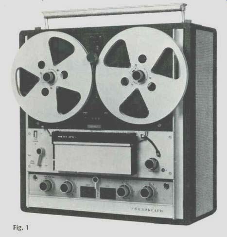
MANUFACTURER'S SPECIFICATIONS:
Maximum reel size: 8 1/4 in.
Speeds: 7 1/2, 3 3/4, 1 7/8 ips. (Available with 15 ips instead of 1 7/8.)
Motors: Three.
Wow & Flutter: Less than .08% at 7 1/2 ips.
Signal to-Noise Ratio: Better than 55 dB referred to 2% distortion.
Tone Controls: Continuously variable bass and treble controls for each channel applicable to playback.
Inputs: Two per channel-Microphone, 10 k ohms, 300 µV to 15 mV; Line, 2 Megohms, 50 mV to 10 V.
Outputs: 600 ohms, 2 V; low-level, 300 mV into 10 k ohms or greater; loudspeaker, up to 10 W into 8-16 ohms.
Dimensions: 16 3/4 in. wide, 17 1/2 in. high, 10 in. deep.
Weight: 49 1/2 pounds.
Price: Chassis only, $599.00; walnut case, model 724A-W, $699.00; portable case, leather-cloth covered, model 724A-P, $699.00. (Also available in mono.)
Imported from England by Elpa Marketing Industries.
The Ferrograph Series Seven represents the first major change in the Ferrograph line in many years, and it is apparent that the changes are well thought out and long overdue. Along the top of the chassis are the carrying handle which retracts flush with the case when not in use, and a strip which contains all the input and output jacks, the fuses, a remote-controlled socket, and the power receptacle, as shown in Fig. 2. The front panel is divided into four sections, with the upper one mounting the power switch and the mechanical speed-control knob, the two reel hubs, the digital counter, and the record button, which is a bar shaped "button" in red, so as to be plainly visible. Among the numerous features in this unit are the reel-height adjustment screws, which permit moving the reels inward or outward so as to wind the tape without its rubbing against the flanges. The reels furnished with the machine are aluminum-flanged, 7 in. in diameter, and they have tape hold-down clamps in the hub which can be released by depressing the opposite end of the clamp through a hole in the flange. The speed for which the transport is set is observed through a window above the knob. The power pilot light is just below the speed-control knob, and another pilot "reset" light serves to indicate when the machine is ready by its absence. When the light is on, something is wrong, as when the mechanical speed control knob is on one speed while the equalization-control is on another--a safety feature. When the red reset light is on, the motors will not run, and after correcting the problem, the FUNCTION lever must be moved to the STOP position to deactivate the relay which controls the reset light.
The next section of the front panel accommodates the FUNCTION lever, a release button-which must be moved to allow the FUNCTION lever to be moved to the STOP, PAUSE and RUN positions. As the lever is moved from these positions to the FAST position, the release button locks the lever out of the operating positions.
The tape-head assembly occupies the center portion of this panel, and on its right is the auto stop guide and the FAST control knob. When the function lever is in the FAST position, the two spooling motors are in series across the line with their junction connected to the arm of the control, while the ends of the potentiometer are connected across the line. Thus, all of the line voltage can be fed to either the rewind or fast-forward motor, providing control of fast spooling from full speed to slow enough for finding a desired spot on the tape for editing.
The next section of the panel has, from left to right, the upper track microphone jack, the equalization selector (which must be in the same speed setting as the mechanical speed-control knob for the machine to run) a dual-concentric record-level control for the upper track, the upper track VU meter, a switch which selects either upper track, stereo, or lower track, the lower-track, VU meter, the lower-track dual-concentric record level control, the speaker level control--also dual concentric-and the lower-track microphone jack.
Below this section, and accessible by tilting outward a section of the aluminum extrusion, is another series of controls which might be termed "auxiliary." At the left is the upper-track "source-tape" switch, a recessed ( screwdriver-operated ) tape-level control which permits adjustment of the meter to indicate the same on both tape and source, the drum-type bass and treble controls, the recessed upper track bias control, a meter switch which may be switched to output, source, or bias, the transfer switch which enables the user to feed a signal from one track to another, followed by the lower-track bias, tone, and meter controls.
Thus it is seen that the machine is equipped with practically all of the possibilities of operation that the recordist could want. It is exceptionally flexible, and with it one can add echo, record sound-on-sound and sound-with-sound, as well as using the machine for the usual applications of a normal recordist.
Operation
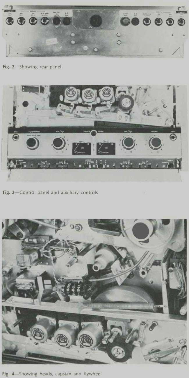
Fig. 2--Showing rear panel
Fig. 3--Control panel and auxiliary controls
Fig. 4-Showing heads, capstan and flywheel
To thread the tape, the head cover is raised and the pressure pads moved away from the heads by a lever at the bottom of the head assembly. This lever also moves the auto-stop arm upward to permit straight-line tape threading from supply reel, past the heads, and across to the outlet slot, and thence to the take-up reel. The pressure pads return to the normal head-contacting position when the threading lever is depressed or when the head cover is closed. Figure 4 shows the heads and the retracted pressure-pad arms. One of the features of the Ferrograph is that it can be put into the record mode or released from it while running. The record function is engaged by depressing the RECORD bar, and it can be released at any time by simply moving a latch ( above the FUNCTION lever) to the left. This permits insertion of some new material into a tape which has already been recorded without the need for cutting and splicing. Another valuable feature is the control of bias from the panel, and the indication on the VU meters of the bias current. More about this later.
Construction
Figure 4 shows the drive from the capstan motor to the capstan itself. The motor is fitted with a heavy stepped pulley of massive dimensions. An idler wheel is drawn into contact with the proper step and the heavy flywheel, also massive (it is 3 3/4 in. in diameter and has a rim thickness of 1/2 in.). Drive to the digital counter is by a flexible cable from the takeup-reel shaft. Solenoids serve to pull the idler into engagement with the stepped motor pulley and the flywheel, and to pull the pressure roller into contact with the capstan. Metal-foil strips can be applied to the tape to stop the machine where desired, and in case of tape breakage or end-of-reel runout, the auto-stop arm stops the motion. Figure 5 shows the underside of the unit, with the replay and tone-control and meter boards to left and right, and the record equalization components at the center, and Fig. 6 shows the record amplifier of one channel at the bottom, and the output amplifier section at the top. Figure 7 shows the capstan motor, together with its capacitor at the center, and the power transformer is visible through the rectangular opening at the top.
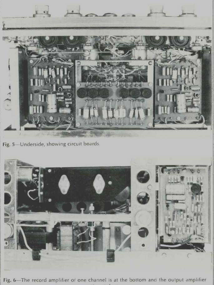
Fig. 5--Underside, showing circuit boards.
Fig. 6--The record amplifier of one channel is at the bottom and the output amplifier section at the top.
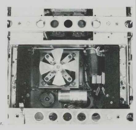
Fig. 7--The capstan motor with its starting capacitor.
Performance
The Ferrograph is an interesting machine to use, with its wide range of features which provide convenient operation. The important information about performance is shown in Fig. 8, which shows the frequency response from a standard tape at 7 1/2 and 3 3/4 ips, and the record/replay response at all three speeds.
Wow and flutter measured .07 percent at 7 1/2, 0.15 percent at 3 3/4, and 0.18 percent at 1 7/8 ips, all of it in the range from 6 to 250 Hz. The 3-percent distortion point occurred at 9 dB above the indicated zero recording level (at 7 1/2), although Ferro graph refers to a 2-percent distortion as their reference. Distortion ranged in the vicinity of 1 to 1 1/2 percent at zero recording level from 100 to 10,000 Hz, and was 1.1 percent at 10 dB below zero level.
Signal-to-noise was measured at 59 dB below the 3-percent point, unweighted, and crosstalk measured-51 dB. For those who are interested, we also measured IM distortion at 6 dB below zero level and noted it at 3 per cent. This measurement has not usually been reported in previous PROFILES, but some readers have indicated an interest in this figure. Bias frequency was measured at 101.5 kHz.
Input signal required for zero recording level measured 0.15 mV at microphone input, and 24 mV at the line input, with both controls at maximum.
Line output for the same level was 2.2 volts, and the power amplifiers delivered a maximum of 15 watts into 8 ohms at a distortion of 2.0 per cent. The built-in speakers--one for each channel--are 4x7 in. oval models. The complete unit employs 34 transistors, 2 FET's, 8 diodes, and two bridge rectifiers.
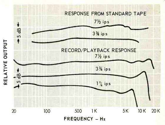
Fig. 8
Ferrograph is to be complimented on the elaborate instruction book furnished with the machine. It is a hard-cover book containing 75 pages of text material and five blank pages for notes. In addition, a complete schematic is furnished, as is a complete parts catalog. If we may be said to have any objections to this unit, it would concern the use of phone jacks for inputs and outputs--but this is a personal prejudice! We think the Series Seven Ferrograph offers many advantages to the serious recordist and can be recommended for consideration.
-C. G. McP.
(Audio magazine, Jun. 1970)
Also see:
Ferrograph RTS-1 Tape Recorder Test Set (Jun. 1972)
Ferrograph Super Seven Model 7504-AHW 4-Track Tape Deck (Equip. Profile, Mar. 1975)
= = = =