MANUFACTURER'S SPECIFICATIONS
FM TUNER SECTION
IHF Sensitivity: 2.5 µV S/N: Mono 64 dB THD: Mono, 0.5%; Stereo, 0.8%. Selectivity: 40 dB Capture Ratio: 2.5 dB. Image Rejection: 46 dB I.F. Rejection: 70dB Spurious Rejection: 85 dB Stereo FM Separation: 35 dB at 1 kHz.
AM TUNER SECTION
IHF Sensitivity: 350 uV /meter. Selectivity: 36 dB. Image Rejection: 40 dB. I.F. Rejection: 40 dB.
AMPLIFIER SECTION Power Output: Four-channel, 15 watts/channel; two-channel strapped, 36 watts/channel. Rated THD: 1.0%. Rated IM: 0.8%. Power Bandwidth: 30 Hz to 30 kHz. Damping Factor: 30. Input Sensitivity: Phono, 2.5 mV; Aux and Tape, 200 mV. Maximum Input Signal: Phono, 45 mV; Aux and Tape, 3.5 V. Frequency Response: Phono, RIAA ±2 dB; Aux and Tape, 20 Hz to 20 kHz . 2 dB. Hum and Noise: Phono, 60 dB; Aux and Tape, 66 dB. Bass Control Range: 12 dB @ 50 Hz; Treble Control Range: ± 12 dB @ 10 kHz. High Filter:-8 dB @ 10 kHz.
GENERAL SPECIFICATIONS
Dimensions: 19 1/4 in. W x 5 3/8 in. H x 16 3/4 in. D.
Weight: 24 1/4 pounds.
Power Consumption: 220W/250 VA.
Price: $369.95.
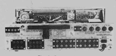
Fig. 1--Rear panel.
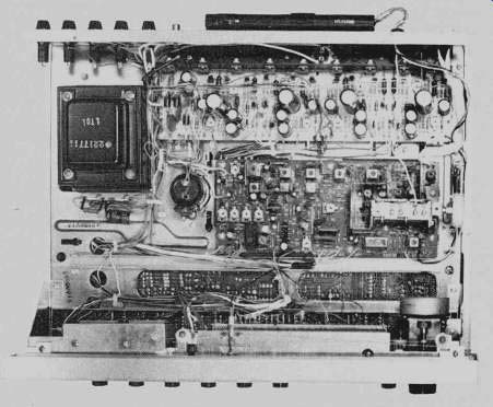
Fig. 2--View of the chassis.
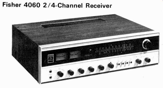
This trim-looking receiver should go a long way towards dispelling the idea that in order to "get into" quadraphonic sound, one needs to apply for a second mortgage on the home and car. Retailing for just about the same price as a good-quality stereo receiver of similar power-output capability, the Model 4060 "2/4-Channel Receiver" offers many features found in higher priced units. While it lacks built-in CD-4 demodulation circuitry, it does incorporate an SQ-matrix decoder circuit which will decode matrix records as well as matrix four-channel FM broadcasts.
The front panel bears a family resemblance to other Fisher receivers. The upper, blacked-out section contains two tuning meters (signal-strength and center-of-channel); mode indicator lights which denote two-channel, four-channel, and matrix settings of the mode switch; well-calibrated FM, AM, and logging dial scales, and a good-sized tuning knob. The lower half of the panel contains a pair of headphone jacks for use with two- or four-channel headphones; a power/speaker switch (which turns on power, selects main or remote sets of speakers, as well as the "strapped," two-channel, higher-power mode); bass and treble controls; rear- and front-balance controls; dual concentric-clutched, master-volume controls; mode switch, and program-selector switch. Four additional push buttons activate such secondary circuits as loudness-contour, high frequency filtering, FM interstation muting, and tape monitoring. By designing the volume control as a pair of friction-clutched dual controls, the need for a front-back balance control is eliminated. The dial pointer of the 4060 is illuminated for easy viewing, and the dial scale numerals light up in a soft blue color when power is applied.
The rear panel, pictured in Fig. 1, is equipped with antenna terminals for 300-ohm FM antenna and external AM antenna connections. There are inputs for phono, four-channel auxiliary (such as the output of a four-channel tape deck), and four-channel recorder-out/tape-in jacks. Well-separated speaker terminal screws accommodate two quartets of speakers for main and remote operation. In the two-channel, "strapped" mode, however, only one pair of speakers can be used.
The reasoning here, of course, is that once a customer owns four speakers he will more than likely want to connect them for quadraphonic use, rather than as main and remote stereo pairs. If desired, however, the latter arrangement could be worked out by setting the mode switch to the two-channel position while leaving the power/speaker switch in the four-channel position. Under those conditions, the same stereo information is applied to front and rear pairs of speakers, which could then be located in different listening locations.
The rear panel also contains an FM detector output jack for future use with an adaptor to decode four-channel, discrete FM broadcasts when and if such broadcast service is authorized by the FCC. Four speaker-line fuses, a power-line fuse, a switched a.c. receptacle, and a pivotable AM ferrite-bar antenna, plus a chassis-ground terminal, complete the rear panel layout.
The view of the 4060 (Fig. 2) with walnut cabinet enclosure removed discloses a neatly laid-out group of circuit-board modules, the centrally located one of which contains the entire AM, FM, and stereo-decoder circuitry. A field-effect transistor is used in the FM front-end, along with a three-section variable capacitor. A three-stage, integrated-circuit i.f. section is used in FM, while the AM section uses a two-section variable capacitor and a three-stage i.f. amplifier.
Tone control circuits are of the negative-feedback Baxandall type, while output stages are of conventional push-pull design and utilize eight medium power transistors mounted on a common heat sink, which can be seen at the rear of the chassis.
Output-circuit protection is afforded by means of the individual speaker-line fuses mentioned earlier. The presence of a full set of four-channel auxiliary inputs would make it easy to add a CD-4 outboard demodulator to this receiver and still permit the use of a four-channel tape deck, since the latter could be connected to the four-channel tape-monitor in-and-out jacks. If the user desired to add a separate matrix decoder to the system (for the purpose of achieving "logic" enhancement of separation- a feature not included in the self-contained SQ-decoder circuit), this accessory could be accommodated as well, since such decoders usually provide four-channel monitor jacks for the then-displaced four-channel tape deck of the system.
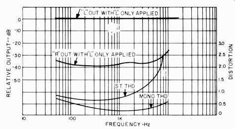
Fig. 3-FM quieting and distortion characteristics.
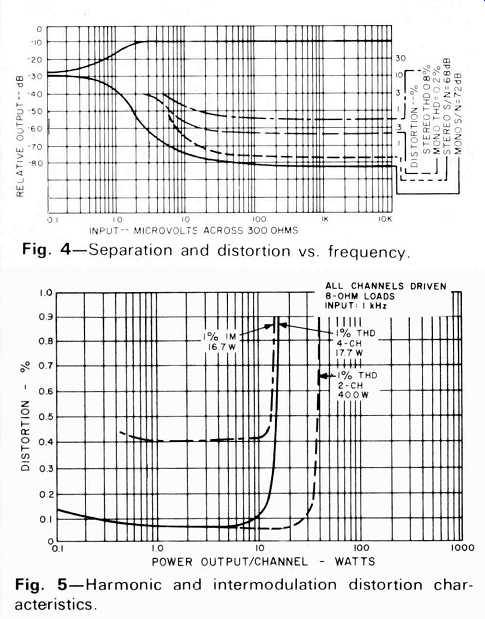
Fig. 4-Separation and distortion vs. frequency.
Fig. 5-Harmonic and intermodulation distortion characteristics.
Tuner Performance Measurements
While the Fisher 4060 claims an IHF FM sensitivity of 2.5 µV, we did better than that in our measurement of the sample supplied to us. It read 2.2 µV and, more importantly, provided an impressive 50 dB of quieting with only 2.5 µV of signal applied. At 6 microvolts, mono THD was down below 1.0%, reaching an ultimate low figure of 0.2% at full (1000 µV) signal strength. Ultimate S/N in mono reached 72 dB, 8 dB better than claimed, while in stereo, best signal to-noise ratio obtained for strong signals was an impressive 68 dB. Stereo switching occurs at an input signal strength of about 7 microvolts, at which point THD is already down to about 1.5%. Ultimate THD in stereo measured 0.76%, a bit better than the 0.8% claimed by the manufacturer. Results of these measurements are plotted in Fig. 3.
Additional specifications confirmed include a capture ratio of 2.5, as claimed, selectivity of 42 dB (a bit better than claimed, but not particularly impressive), and spurious response rejection of 85 dB as claimed.
Figure 4 shows stereo FM separation as well as THD versus frequency for both mono and stereo. Mid-frequency separation measured 38 dB, decreasing to 25 dB at 10 kHz, and 34 dB at 50 Hz. THD in mono remains below 0.5% from about 100 Hz to 8 kHz, never rising above 0.65% at any frequency measured. Stereo THD remains well below 1.0% for frequencies below 2 kHz, rising to 2.7% at 7 kHz, largely because of non-harmonically related "beat" frequencies which appear at the higher frequencies.
AM performance of the Fisher 4060 was just average, as might be expected from this typical, minimal AM circuit design. Orientation of the ferrite bar antenna did enable us to receive the expected number of AM stations reasonably well, but measured signal-to-noise did not exceed 40 dB. THD under test conditions measured 1.3% for 30% modulation at 1000 µV.
Amplifier Measurements
With all four channels driven with a 1 kHz signal, and in the four-channel mode, THD at rated continuous-power output of 15 watts per channel (into 8-ohm loads) was a mere 0.12%. We were able to drive the amplifiers to an output of 17.7 watts each before reaching rated THD of 1.0%, as plotted in Fig. 5. Rated IM of 1.0% was reached for an output of 16.7 watts per channel, again better than the 15 watts per channel claimed. THD was also plotted for the "strapped" two-channel mode, in which front and back channels are paired together to provide more than twice the power per channel for stereo use, compared with quadraphonic operation of the receiver. Under these conditions, power output reached 40 watts per channel (as against 36 watts claimed) before rated THD of 1.0% was noted. In our opinion, Fisher's technique of having the "strapping" switch available as a front-panel control (part of the speaker selector switch), and not having to reconnect the pair of desired speakers to special sets of speaker terminals, are both very desirable aspects of this circuitry. Even the quadraphonic listener may, occasionally, want to "switch back to stereo" (with only two of his four speakers playing), either for comparison purposes or because of musical preferences, and it is nice to be able to affect this switching without having to go around to the back of the unit--which may well have been custom-installed in a cabinet or mounted on a shelf against the wall.
Power bandwidth, plotted in Fig. 6, extends from 25 Hz to 25 kHz, as against 30 Hz to 30 kHz. The 15-watt-per-channel capability at less than 1.0% distortion extends all the way out to 20 kHz or better, but at the bass end of the spectrum, that THD is reached for a frequency of 70 Hz, while at 50 Hz, attempting to reach full power output results in a THD of 2.0%. At half-power output (7.5 watts per channel), the "under 1.0%" THD reading is maintained down to 20 Hz.
Tone-control range is typical of this type of circuit and is plotted in Fig. 8. While the high frequency filter has a slope of only 6 dB per octave, its crossover point is set somewhat higher than is obtained by full counterclockwise rotation of the treble control. This makes it a bit more effective in reducing scratches and hiss than would be possible if the treble control were rotated fully to achieve the same effect-pre serving some of the higher frequency musical content of the programming. Loudness-control contouring was measured for a setting of-30 dB from maximum volume, and corresponds closely with Fletcher-Munson prescribed effects. Slight treble emphasis is also provided in this particular loudness circuit.
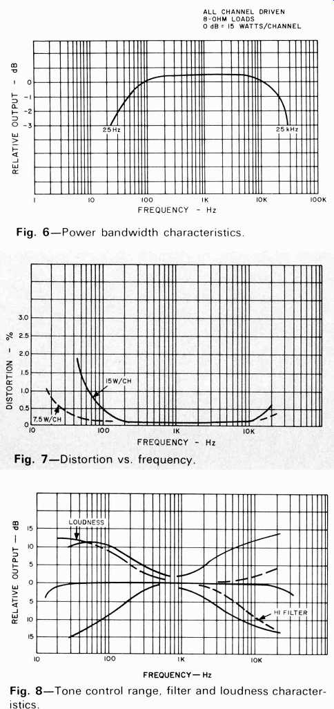
Fig. 6--Power bandwidth characteristics.
Fig. 7--Distortion vs. frequency.
Fig. 8-Tone control range, filter and loudness characteristics.
Miscellaneous Measurements
Overall frequency response of the Fisher 4060 was 16 Hz to 28 kHz + 3 dB. Volume-control tracking (operating the twin controls clutched together) was accurate within 1 dB down to -50 dB from full clockwise setting. Phono hum measured -61 dB, referenced to 2.5 mV input, while phono over load did not occur until an input of well over 100 mV was applied. Fisher conservatively rates phono overload at only 45 mV--somewhat of an "injustice" to this important parameter we think. Residual hum and noise in AUX position measured -75 dB, while amplifier residual noise and hum with volume set at minimum was down some 93 dB. Muting level on FM (which is non-adjustable by the user) is set for a threshold of 25 microvolts-a bit too high for our taste in view of the fine quieting characteristics of the receiver. With no filters inserted between the output of the receiver and our meters, residual 38 kHz output products were down 44 dB in stereo FM, a bit high for those tape recorders not equipped with "multiplex filter" circuits. While FM and AM calibration were "right on" across the dial scale, we found that the center-of-channel meter was slightly "off center" for minimum distortion tuning of FM. This minor flaw is, of course, easily corrected by a slight touch-up of detector alignment and is probably not typical of production units in general.
Listening Tests
Using medium- and high-efficiency speaker systems, the Fisher 4060 performed well both as a stereo receiver and in quadraphonic use. There was plenty of sound in our 14 x 18 ft. listening room, though at very high levels, when playing quadraphonic matrix records with primary programming information coming from all channels, it was possible to detect some distortion during particularly bass-heavy passages. While this is not the receiver for achieving 110 dB sound pressure levels in listening rooms, few home listeners would ever demand that kind of ear-splitting level. Separation and spatial effects attained while listening to some recent SQ-matrix releases were surprisingly good, when one considers the fact that no logic circuits are present in the decoder circuits. The recent emphasis in the literature on the need for very sophisticated and costly logic circuitry in reproducing matrix quadraphonic records may well be doing a disservice to the listening public, since from a musical point of view, a well-engineered and produced SQ record can provide all the "four channel effect" many listeners demand--even in the absence of such extra circuitry, as evidenced by the performance of the Fisher 4060. Certainly, if you are interested in a versatile receiver that will do well in stereo or four-channel, performs more than adequately in FM and stereo FM, and is compact, good-looking, and moderately priced (considering its features), the Fisher 4060 represents one of the easier ways of "getting into four-channel sound."
-Leonard Feldman
ADDENDUM
The following table was inadvertently omitted from the ESS amp and preamp equipment profile in the May issue. We regret this oversight.
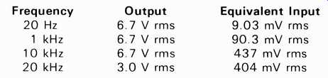
Table 1--Phono Overload
(Audio magazine, Jun. 1974)
Also see:
Fisher 801 Four Channel AM/FM Stereophonic Receiver (Equip. Profile, Jul. 1972)
Fisher RS-Z1 Receiver (Equip. Profile, Aug. 1990)
Fisher ST-425 Speaker System (Jan. 1975)
= = = =