MANUFACTURER'S SPECIFICATIONS
FM TUNER SECTION. IHF Sensitivity: 1.7 µV. Harmonic Distortion (Mono): Less than 0.35%. S/N Ratio: 60 dB. Selectivity: 60 dB. Spurious Response Rejection: 105 dB. Image Rejection: 70 dB. I.f. Rejection: 85 dB. Capture Ratio: 1.5 dB. Stereo FM Separation: 36 dB @ 400 Hz.
AM TUNER SECTION. Sensitivity: 10 V. Selectivity: 55 dB. Image Rejection: 45 dB. I.f. Rejection: 40 dB.
AMPLIFIER SECTION. Power Output: 44 watts per channel at 4 ohms. THD @ 1 kHz: 0.5%. IM: 0.8%. Power Bandwidth: 20 to 25,000 Hz, 4 ohms. Damping Factor at 4 ohms: Greater than 10. Input Sensitivity: PHONO, 2.7 mV; AUX 1 & 2, 200 mV; TAPE MONITOR, 300 mV. Hum and Noise: PHONO (6 mV reference), 60 dB; AUX 1 & 2 (400 mV reference), 65 dB; volume at minimum, 90 dB. Frequency Response: PHONO, RIAA ±2 dB from 30 to 15,000 Hz; AUX 1 & 2, 20 to 25,000 Hz +1.5 dB. Maximum Input Signal for 1.0% THD: PHONO, 50 mV; AUX 1 & 2, 3.5 V. Bass and Treble Control Range: 24 dB at 50 Hz and 10 kHz respectively. Subsonic Filter: 12 dB per octave below 10 Hz. High Frequency Filter: 12 dB per octave, with 5 kHz crossover point.
GENERAL. Dimensions: 17 3/4 in. W by 6 in. H by 16 1/2in. D. Weight: 35 lbs. Maximum Power Consumption: 320 watts.
Suggested Retail Price: $749.95.
Just as we finalized our laboratory set-up with what we consider to be a most flexible, high-quality stereo electronic measurement set-up, along came the Fisher 801 four-channel receiver-requiring new standard load resistors, new input and output switching facilities, and a new approach to receiver evaluation. (As of this writing, we don't believe that Tektronix scopes come with "quadruple" traces-so we had to move the probes from front to rear channel outputs for the time being.)
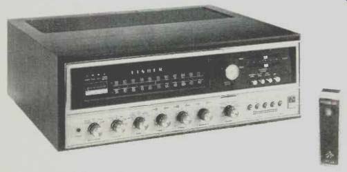
In any case, the four-channel receivers are here-and if the Fisher 801 is any indication of what's to come, then manufacturers are going to have to use a lot of ingenuity to cram channels of amplification and control facilities into the … occupied by just two channels of audio …. That, however, is just what the Fisher engineers have managed to do, as is evidenced by the overall dimensions shown above. In the front panel view shown, the receiver seems to have no more controls than a conventional stereo receiver, but as you examine these controls carefully you realize that a few new ones have been added to take care of the new requirements of quadraphonic sound control. Considering the lower portion of the panel, we find a stereo phone jack at the extreme left. We wondered why, in a four-channel receiver, Fisher failed to include double phone jacks to take care of the variety of four-channel headphones which are rapidly appearing on the market. We discovered that, in fact, the stereo phone jack mixes front and rear channels together, so that when using conventional stereo phones, all program material is heard, rather than just "front only" or "rear only." Reading across from left to right we find a four-position tape-monitor switch (FRONT, REAR or FRONT-PLUS-REAR inputs can be put in the monitor mode), a program source selector switch, a mode switch with positions for MONO, STEREO, DISCRETE FOUR CHANNEL, a MATRIX setting for popular recordings and a MATRIX setting for classical recordings. More about the differences between these two matrix settings later. Dual concentric BASS and TREBLE controls come next, and the "dual concentricity" is used as a means for separately adjusting bass and treble for front and rear channels, rather than for left and right. A dual balance control (again, using concentric knobs) follows, as well as a five-position speaker selector switch which, in addition to Its MAIN, REMOTE, MAIN-PLUS-REMOTE and PHONES ONLY positions also includes a position for turning the entire receiver off. A series of five push-push buttons along the lower right of the front panel serves to activate HIGH filters for front and rear channels, MUTING of FM for interstation silence, and front and rear LOUDNESS compensation circuits.
The upper portion of the panel contains the usual AM and FM dial calibration and tuning knob for manual tuning. A dual-purpose meter serves as a signal-strength indicator and, when the Autoscan modes of tuning are used, the upper portion of the meter becomes illuminated, disclosing a miniature 88-108 MHz dial. Above the meter are four illuminated designations which correspond to the setting of the Mode switch (MoNo, STEREO, 4- CH.) and denote the reception of a stereo FM signal. The upper right portion of the panel contains linear slide controls for adjusting front and rear volume and four more push-buttons associated with the Autoscan tuning modes. Depressing the first of these buttons transfers the tuning function from the manually rotated tuning knob to the electronic tuning circuits previously seen in other Fisher receivers. For continuous scanning of the dial (from low end towards high end), the second button is depressed.
While held in the depressed position, the meter needle (now acting as a small dial scale) moves upwards denoting approximate frequency. As soon as the button is released, the electronic circuits "lock into" the next station up the scale. The next button acts in a similar fashion, except that the. electronic circuits advance the tuning one station at a time, while the final button is used to apply AFC (Automatic Frequency Control) when tuning manually. (In the case of Autoscan, AFC is not needed, a station lock-on is determined by the Autoscan circuits themselves). It should be noted that the Fisher 801 comes equipped with a small hand-held, battery-operated remote control unit identified as Model WT-50. This device emits a super-audible frequency which is picked up by a suitable transducer on the front panel of the 801, activating the Autoscan circuits in much the same way as depressing the front panel continuous tuning Autoscan button. A more elaborate optional remote control device (RK-40) is available which duplicates both the CONTINUOUS and the ONE STATION buttons on the 801 Autoscan section, but this latter device must be connected to a corresponding socket on the rear of the receiver and is equipped with a 20-ft. cable for that purpose.
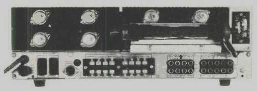
Fig. 1-Rear panel.
The rear panel of the 801 is shown in Fig. 1. A line fuse, two convenience a.c. outlets and the remote control socket are located at the lower left, adjacent to eight speaker output terminal pairs. The terminals are practically "short circuit proof," in that you need only depress each terminal (disclosing a small hole) and insert the stripped end of your speaker wire. Releasing the terminal clamps the wire in place so there is no danger of shorts from loose strands of wire. There are four TAPE MONITOR IN jacks and four RECORDER OUT jacks and four jacks each for AUX 1 and AUX 2 inputs. Finally, a pair of MAGNETIC PHONO INPUT jacks and a GROUND terminal complete the lower panel layout. The upper portion of the rear panel contains a massive ferrite antenna bar as well as screw terminals for connection of external FM and AM antennas.
Shorting bars are used to connect internal FM and AM antennas, and these must be rotated out of the way if either outdoor AM or FM antennas are to be connected. Although our photo discloses six of the eight output transistors (two are obscured by the AM bar antenna), these devices are normally covered by the "cage" supplied with the receiver. We simply removed the cage to examine the layout of the receiver proper, a photo of which is shown in Fig. 2.
Identical stereo amplifier modules, each equipped with its own heat sink and output transistors can be seen in the photo of Fig. 2. The chassis surface is literally "filled to the brim" with other circuit modules and use is made of the popular "mother board" principle, in which sub-modules (such as the stereo multiplex section) are plugged right into more major modules (such as the AM-FM i.f. section, which is the largest single board module in the receiver.) Boards are even used to make interconnections from one major module to another, reducing conventional hand wiring to a minimum.
The photo speaks for itself, as far as the "density of parts" of the 801 is concerned, and helps to explain how Fisher was able to get so much into such a small (relatively speaking) package.
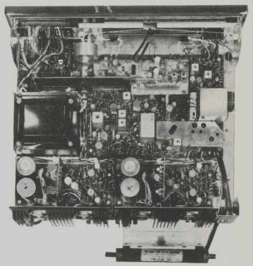
Fig. 2--View from the top.
While we, of course, were most interested in operating the 801 as a four-channel receiver (for both discrete and matrix source material), it should be pointed out that other interesting alternatives are available. For example, one could connect four speakers in one room, two speakers in a second room, and two more speakers in a third room. One could even connect stereo pairs of speakers in up to four rooms if four-channel reception is not the objective at the moment. By depressing only one (front or rear) tape monitor button, it is possible to reproduce taped sound in one location plus any other signal source (FM Stereo, AM, etc.) in another location, etc. All these possibilities (and there are several more) are clearly explained in the well written instruction manual that comes packed with the 801.
Performance Measurements
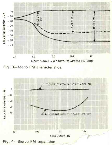
Fig. 3-Mono FM characteristics.
Fig. 4-Stereo FM separation
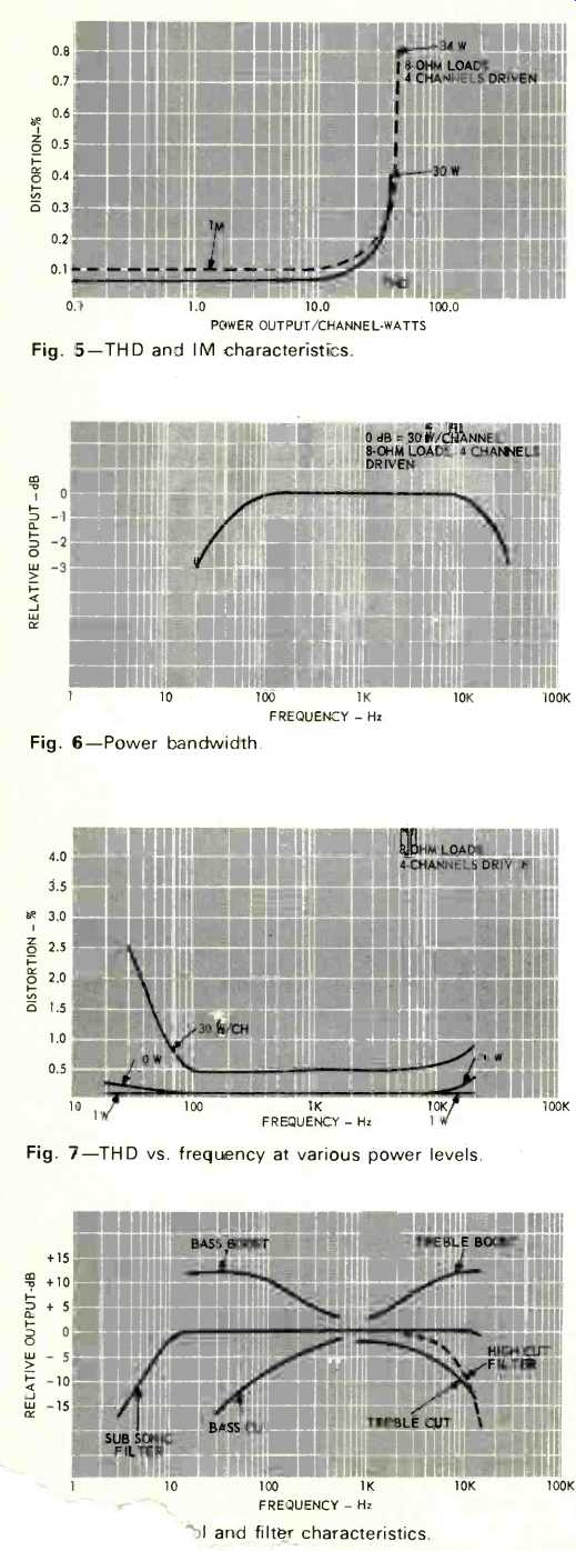
Fig. 5--THD and IM characteristics.
Fig. 6--Power bandwidth.
Fig. 7--THD vs frequency at various power levels.
Fig. 8-...and filter characteristics.
The FM tuner section's mono characteristics are shown in Fig. 3. IHF sensitivity fell just a bit short of the 1.7 µV claimed, coming in at 1.9 µV, while the ultimate S/N reached 66 dB at just over 50 µV. A very listenable 50 dB of S/N was reached at just under 4µV (a very good figure indeed), while THD measured 0.4% in Mono and just over 0.7% in Stereo. While the muting button depressed, threshold for muting occurred at 8µV, a bit higher than usual. As is true with other Fisher products we have tested, manual timing is smooth and calibration is quite accurate.
Stereo separation characteristics are plotted in Fig. 4 and conform very nicely to stated separation figures. High end separation remains above 20 dB up to 10 kHz.
In the manufacturer's specs, all sorts of power figures are quoted; we didn't include the 250 watt ± 1 dB Music Power at 1 kHz, 4 ohms, nor the 200 watt IHF Dynamic Power rating at 4 ohms although they appear in Fisher's Operating Manual.
In testing, we simply increased power output (all four channels driven) until we reached rated THD of 0.5%, and that occurred at 30 watts per channel, as shown in the graph of Fig. 5. With all four going full blast, this is 120 watts rms total. In the case of four-channel receivers, one might argue that driving all four channels simultaneously to make an rms power measurement is a bit unfair, but since the four-channel recordings we have heard so far have primary program material in all four channels most of the time and in view of the fact that under certain circumstances the receiver can be used as two stereo systems, we must adopt this course in reviewing the 801 and will do so in evaluating all future four-channel receivers which fall to us.
In any event, rated IM of 0.8% was reached at a power output level of 34 watts per channel, as is also shown in Fig. 5. Power bandwidth, shown in Fig. 6, extends from 20 Hz to 30 kHz, a bit better than claimed, but of course this is all referenced to our 30 watt per channel point.
Distortion versus frequency at power levels of 30 watts, 10 watts and 1 watt per channel are shown in Fig. 7 and, as can be seen, at 30 watts of output the THD remains reasonably low only down to about 50 Hz. At 10 watts per channel output, however, THD never exceeds 0.3% at any audible frequency and at a nominal 1 watt level, THD at all frequencies is essentially that of our audio generator.
Tone control and filter characteristics are depicted in Fig. 8, while square wave response at 40 Hz and 20 kHz is shown in Fig. 9.
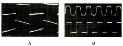
Fig. 9--Square wave response at A, 40 Hz, and B, 20,000 hz.
Listening Tests
As usual, Fisher's tuner section performed flawlessly and the Autoscan features are very worthwhile. Including the "free" remote control was, we feel, a very, good move on the part of the company, for, even though it performs only a station-changing function, the WT-50 is worth having and using. Incidentally, whether or not the muting button is depressed, once you elect to tune by Autoscan circuitry, there is no interstation noise while tuning takes place. We logged 46 listenable signals with one orientation of our 5-element outdoor Yagi array and of these, 24 were stereo signals. With muting added to the circuit, this number was reduced to 42 stations, indicating that 4 of the previously received stations were coming in at signal strengths of under 8µV but were still acceptable.
In listening to the four channels of audio, utilizing the two "matrix" systems incorporated by Fisher Radio, we noted that, in general, synthesis of "four-channel" effects in the "pop" mode was very much akin to the synthesis obtained using the Electro-Voice Stereo-4 decoder system (as opposed to the CBS-SQ proposal) in that front-to-rear separation is quite extreme, with little separation obtained between rear-left and rear-right. In the classical mode, there seems to be a noticeable roll-off in highs in the rear channels justified on the basis of the theory that a concert hall's reverberance and reflections usually contain fewer highs than the dominant or primary program material. The effects achieved with this built-in 2+2 decoder are quite good when using stereo source material. In the case of encoded four-channel material, our library of E-V encoded discs seemed to be reproduced more faithfully (per the intent of the original mix) than did the few SQ discs in our possession. Of course, when listening to four channel tapes, the decoder circuitry is by-passed entirely and the totally satisfying experience of discrete four-channel listening cannot be denied. So much for the four-channel capabilities.
Considered from the point of view of amplifier quality versus price, we found that the amplifier sections were able to drive our low efficiency speakers with no audible distortion to fairly high levels. Since we do not have eight low efficiency speakers on hand, we connected four 8-ohm loads to the remote terminals and again listened to the four channels in our main listening area. Under these circumstances, certain highly dynamic passages of a four-channel SQ disc (classical, at that) seemed to strain the power handling ability of the amplifiers-particularly at the low end and most notably in the front channels (since dominant information was contained in front channels). Ordinarily, however, we doubt if a user would actually have two four-channel set-ups going full blast in two locations at the same time.
Fisher Radio is to be commended for their ingenuity in producing such a feature-packed receiver in such an attractive and compact package. While there are, of course, standard two-channel stereo amplifiers and receivers which might boast more power as well as tuners with better sensitivity or selectivity, the Fisher 801 does indeed provide 30x4 watts rms or 120 watts total, certainly good value for the price. The performance of the tuner section, of course, speaks for itself.
Summing up: The Fisher 801 can be recommended to those who desire good four-channel performance in a compact receiver together with a broad range of automatic tuning and remote speaker features.
-Leonard Feldman
(Audio magazine, Jul. 1972)
Also see:
Fisher 4060 2/4-Channel Receiver (Jun. 1974)
Fisher RS-Z1 Receiver (Equip. Profile, Aug. 1990)
Fisher ST-425 Speaker System (Jan. 1975)
JVC R-X80 Receiver (Nov. 1983)
= = = =