FISHING THE DOWNSTREAM BIT

A Compact Disc is a thing of beauty, especially if you angle it just right so you can see your own reflection. When you see that mug smiling back at you, it's hard to believe that you're looking at 10 billion pits spiraling around that mirrored surface.
Actually, they're pretty hard to see don't even bother trying with a conventional microscope. Just to make sure there is really something there, I recently put a disc under a scanning electron microscope and even it had a hard time seeing the pits.
The pits, as we saw last month, are only a physical manifestation of some complicated data coding, including multiplexing, interleaving, parity, error protection, and EFM (eight-to-fourteen modulation). That coding takes place when the CD master tape is made, and the pits are derived from it at the lathe when the master disc is cut. But the task of deciphering everything falls to your CD player every time you listen to a tune. Let's jump back into the bit stream and examine decoding.
The CD player must read the channel bits from the disc, process them, and deliver an analog audio signal to its output jacks. This requires a hefty amount of signal processing, and the complexity of the task accounts for the design differences among players, but the overall scheme is always about the same. The story begins at the player's optical pickup . . . .
When the laser beam is reflected or dispersed at the disc surface, the varying intensity of the returned beam is detected by a four-quadrant photodiode sensor. It is the voltage from the sensor which is ultimately transformed into the analog audio-signal output.
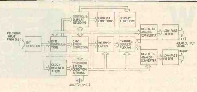
However, important signal processing must first occur to properly convert the encoded data to an analog signal, as illustrated in Fig. 1. The signal en coded on the disc utilizes EFM, which specifies that the signal be comprised of not less than two or more than 10 binary zeros between 0-to-1 transitions (pit edges). This results in pit lengths expressed in a variety of combinational patterns from three to 11 units long, which, in turn, sets the frequency limits of the EFM signal read from the disc. Sometimes, this range is referred to as a 3T-11T signal, with T representing the period of one bit.
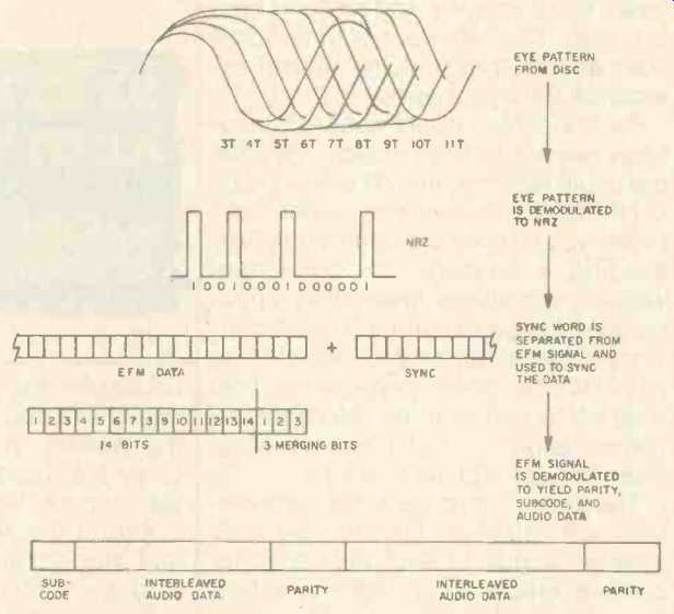
The photodiode and its processing circuits produce a signal resembling a series of high-frequency sine waves, called the EFM signal, in which the minimum time for 3T is approximately 700 nS; it is sometimes referred to as the r.f. signal or the eye pattern. The information contained in the eye pat tern is shown in Fig. 2. Whenever a player is tracking data, the eye pattern is present, and the quality of the signal may be observed from the pattern. For example, a skewed disc would result in a distorted eye pattern. Although this signal is comprised of sine waves, it is truly digital; in fact, it undergoes processing to convert it into a series of square waves more easily accepted by the digital circuits which follow. This does not affect the encoded data, since it is the width of the EFM periods which hold the information of interest.
Following conversion of the eye pattern to square waves, the signal is in NRZ (nonreturn to zero) form, the classic representation in which a high level is a one and a low level is a zero. The first data to be extracted from the NRZ signal are synchronization words-frame-synchronization bits which were added to each frame during encoding. This information is used to synchronize the 33 symbols of channel information in each frame, and a synchronization pulse is generated to determine whether the digital information in each bit is a one or a zero.
The EFM signal is now demodulated so that every 17-bit EFM word again becomes eight bits. Depending on player design, demodulation is accomplished by logic circuitry or by a look up table--that is, a list stored in memory which uses the recorded data to refer back to the original patterns of eight bits. Since interleaving was the last signal-processing step prior to modulation, de-interleaving is the first processing step after demodulation. A random-access memory is used to properly delay and de-interleave the data; following this operation the data again exist in proper sequence, as audio data words with error protection.
During decoding, a buffer is used; a disc's rotational irregularities might make data input to the buffer irregular, but clocking ensures that the buffer output is precise. To guarantee that the buffer neither overflows nor under-flows, a control signal is generated according to the buffer's filled level at a given moment and is used to control the disc's rotating speed. By varying the rate of data from the disc, the buffer is maintained at 50% capacity. It's like water behind a dam being re leased at a controlled rate through the turbines, except we also have control over how fast the snow is melting in the mountains.
Following demodulation, data is sent to a Cross Interleave Reed-Solomon Code (CIRC) decoder for error detection and correction. The CIRC is based on the use of parity bits and an inter leaving of digital audio samples. Be cause of interleaving, data lost from one frame can be reconstructed from information contained in another frame. The correction circuitry thus contains an internal memory able to work with many frames at once. The CIRC permits complete correction of burst (continuous) errors up to about 4,000 bits, and recovery through interpolation (approximate correction) of up to about 12,000 bits. If the error count exceeds the correctable limit, a second circuit provides for muting of the audio signal.
We'll reserve exhaustive explanations of error protection for future columns; meanwhile, a quick summary will do. The CIRC strategy uses two decoders, C1 and C2. During encoding, two kinds of parity bits were added, P and 0 (not to be confused with the PQ subcode!). During reproduction, P parity is checked first during C1 decoding; random, short-duration errors are corrected, and longer burst errors are flagged and passed to C2.
In C2 decoding, Q parity and longer interleaving intervals permit correction of burst errors, and errors which might have occurred in the encoding pro cess itself (rather than in the medium) are corrected. As in C1, uncorrected errors are flagged and passed on.
Interpolation and muting circuits follow the CIRC in a Compact Disc player; in this stage, uncorrected words are detected via flags and dealt with, while valid data passes through, unprocessed. Interpolation is the technique of using valid data surrounding an error as a basis for an approximation of the erroneous data; errors are thus not corrected, but concealed. However, because of high correlation between music samples, concealment by interpolation is generally quite successful.
Methods vary from player to player according to the degree of interpolation used. In its simplest form, zero-order interpolation holds the previous value and repeats it to cover the missing or incorrect word. In first-order interpolation, the erroneous word is replaced with a word derived from the mean value of the previous and subsequent data words.
For continuous errors, muting is employed as a last resort; bad data passed on to the D/A converter could result in an audible click, whereas muting is almost always inaudible. Muting is accomplished smoothly by beginning attenuation several samples before the invalid data, muting the invalid data, and then smoothly restoring the signal level.
It should be noted that CD players are not created equal in terms of error protection. Any player's error-protection ability is limited to the success of the strategy chosen to decode the CIRC code on the disc and to perform interpolation. It is hoped that manufacturers will begin to publish meaningful specifications for error-protection performance.
Following error correction, the bit stream must undergo one final manipulation. Left and right audio channels must be delineated and their respective samples joined together in the same sequence and at the same rate in which they were recorded. Following this process, the data has been reconstituted to the player's best ability. After a quick trip through the D/A converters and low-pass filters, the signal is ready for amplification.
The Compact Disc bitstream is, obviously, a little trickier than one might assume. In the interest of density and robustness, the data must undergo some sophisticated processing during both encoding and decoding. I guess that's all the more reason to appreciate the sound your CD player delivers. So next time you are listening to the Trout Quintet, remember the bit stream it came from.

Fig. 1--CD decoding system.

Fig. 2--Demodulation and decoding, from r.f. signal to subcode, parity and
audio data.
(adapted from Audio magazine, Jun. 1985; KEN POHLMANN )
= = = =