FILTERS Á LA ANALOG

Good evening, sir! Welcome to the Domain Restaurant. A table for one? This way, please. The chef's specialty today is filter á la analog, traditional fare, but our special brick-wall recipe adds some unexpected spiciness. Medium-rare? I hope you enjoy your meal."
If purchasers of CD players were gourmets and hi-fi salesmen were waiters, that scenario would pretty much summarize the current state of affairs.
A lot of analog filters are being consumed, and while they might seem innocuous enough, the particularly steep kinds we cook up for digital audio applications might be causing some unexpected heartburn. In fact, the more we look at analog filters, the more suspicious we become of their potential contamination of digitized audio. Ironically, much of the golden-ears consternation concerning digital audio recorders and players might be due to the fact that most of those systems employ filters which are analog in design.
Filtering is an unfortunate fact of life for digital audio systems. An input antialiasing filter must precede the digitization system to uphold the Nyquist Theorem's criteria for lossless sampling. Specifically, the highest sampled audio frequency must be no more than half the sampling frequency. The output filter might have an identical design to that at the input, and it similarly filters out all frequencies above half the sampling frequency, but its function differs. The analog signal at the output of the digital-to-analog converter is a pulsed amplitude-modulation waveform, easily spotted by its staircase appearance. Those sudden shifts in amplitude represent high-frequency components not present in the original analog waveform; those artifacts of sampling must be removed to create a smooth waveform. The output filter is, in fact, sometimes referred to as a smoothing filter.
Engineers have been designing filters for a long time; thus, at first glance, there should be little trouble with this particular assignment. Both the input and output filters can share an identical analog design, and the design criteria can be easily summarized. Ideally, we would like to attenuate all audio frequencies above the half-sampling frequency yet not affect the lower frequencies. Moreover, we would like that transition to occur instantaneously so that the usable band space is extended as far as possible to yield an extended and flat frequency response. Thus, an ideal filter would have a flat pass-band (the range the filter passes with less than 3 dB of attenuation), an immediate, or brick wall, filter characteristic, and a stop band (the frequencies the filter is designed to eliminate, for all practical purposes) attenuated to below the system's quantization resolution. In addition to these frequency-response criteria, an ideal filter would not affect the phase of the signal or any other time domain characteristic.
Although an ideal filter may be approximated in practice, its implementation presents a number of engineering challenges; a brick-wall design means compromise in other specifications, such as flat pass-band and low phase distortion. To alleviate the problems of a brick-wall response, we could design filters with more gradual cutoff; these, for example, would not exhibit phase nonlinearities. However, the frequency of the half-sampling point would have to be increased to make sure that it was placed in a sufficiently attenuated part of the filter characteristic. Therefore, a higher sampling frequency, perhaps three times higher than that required for a sharp cutoff filter, would be needed to achieve the same frequency response. To limit the sampling rate and make full use of the band-space below the half-sampling point, a brick-wall filter, at both the input and output of the digitization system, is the only alternative. Our problem is thus stubbornly defined.
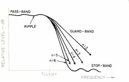
Let's consider an output filter design, such as one found in a Compact Disc player. With a sampling frequency of 44.1 kHz, the output filters (one for each channel) are usually designed for flat response from d.c. to 20 kHz (Fig. 1); this provides a guard-band of about 2 kHz to ensure that attenuation is sufficient at the half-sampling point.
The pass-band undoubtedly exhibits some frequency irregularity, called ripple, which is typically specified to be less than ±0.1 dB. The stop-band's attenuation is designed to be equal to or better than the system's dynamic range, as determined by word length; a 16-bit system would require a stop band attenuation of greater than 95 dB. The stop-band also typically exhibits ripple.
Given the filter characteristics, several filter types may be employed, each corresponding to specifications incorporated in mathematical polynomials such as Bessel, Butterworth, Chebyshev, or elliptical polynomials.
Each of these functions defines a basic design mechanism which may be cascaded (repeated in series) to sharpen the cutoff. These high-order filters closely approximate the ideal filter's brick-wall response. A passive Chebyshev design is shown in Fig. 2; the steepness of the cutoff increases dramatically as the filter's order increases.
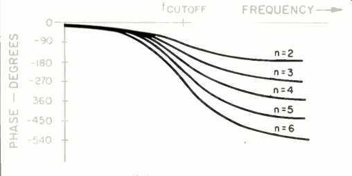
Unfortunately, the phase shift increases as well (Fig. 3). Compact Disc players might require a ninth- or thirteenth-order filter; the cutoff looks like the north rim of the Grand Canyon, but the phase shift might exceed 360° at 20 kHz.
We've come face-to-face with the problem: A massive high-frequency phase shift. The big question is, is high-frequency phase shift audible, and if so, how bad is it? John Meyer has examined that question and presented some conclusions, along with speculations about phase shift-that is, the time delay of signals [1]. First, absolute, non-frequency-dependent delay is inaudible. The Solti recording of Das Rheingold is 26 years old, which is a lot of delay, but the CD doesn't suffer phase distortion because of it. But Meyer has shown that the frequency-dependent delays called group delays, increasingly present toward the cutoff frequency of the analog filter in the CD player, do indeed cause phase distortion.
Exactly what is group delay, and is it audible? A conceptual worst-case example, suggested by Richard Heyser, proposes a two-way loudspeaker with the tweeter mounted about a mile behind the woofer. If properly equalized, steady-state tones would sound fine.
But when the tone ended, we would hear sound emanating from the tweeter a full 5 S after the sound from the woofer had passed by. Likewise at the onset of a tone, the tweeter's attack would arrive 5 S late. Obviously, such massive frequency-dependent delays would be audible. But what about a real brick-wall filter, in which the delay at 20 kHz might be 300 µS relative to 0 Hz? Is that audible? Well, Meyer thinks it is, and he has designed a filter to correct for it. Meyer's circuit uses complementary delays to achieve an absolute delay up to 18 kHz, and a rise to 150 N.S at 20 kHz.
Problem solved? Well, not quite. In fact, the closer we look at brick-wall analog filters, the more consternation arises. Most brick-wall filters exhibit resonance near the cutoff frequency, which results in ringing; this, in turn, causes coloration in frequency response. The sharper the cutoff, the greater the propensity for ringing.
And that's not all: Thomas Stockham and Roger Lagadec have identified a new and somewhat mysterious phenomenon called time-domain dispersion [2]. In their experiments, so-called "perfect" filters, with no phase distortion or ringing, affected test signals with pre- and post-echoes (32 dB, 40-mS delay) placed symmetrically about a waveform's attack. Subsequent tests linked the echo pairs to the filter's ripple; both the ripple amplitude and ripple frequency seemed to contribute to the observed dispersion. The frequency variation caused by ripple in itself is inaudible, but the artifact the ripple produces might provide a new and unexpected clue toward ah understanding of our perception of digital audio. Fortunately, in practice, dispersion can easily be licked with a stricter ripple tolerance. Lagadec has suggested ripple amplitude of ± 0.001 dB. Thus, we are learning that the filters necessary in an audio digitization system are by no means trivial design exercises. It is becoming increasingly clear that these analog circuits demand careful design specification to avoid contamination of the audio signal. High-frequency phase shift, ringing, and dispersion must all be considered. Maybe our initial design criteria for a severe brick-wall filter were inappropriate. As Lagadec has asked, are such "macho" filters really necessary? Some experimenters are using digital audio systems without any filters.
As noted, it is supremely ironic that analog circuits should cause digital audio so much trouble. If only there were a way to avoid analog filters and perform the same function more efficiently, perhaps even elegantly. Well, there is a way. Next month we'll taste test filters á la digital.

Fig. 1--How filter slope increases with filter order.

Fig. 2--A passive, low-pass Chebyshev filter, showing cascaded design. The
filter's "order" is the number of cascaded stages.

Fig. 3--How phase shift increases with filter order.
References
1. Meyer, John, "Time Correction of Anti-Aliasing Filters Used in Digital Audio Systems," Journal of the Audio Engineering Society, March 1984.
2. Lagadec, Roger and Thomas Stockham, "Dispersive Models from A-to-D and D-to-A Conversion Systems," Preprint No. N-2097 (H8), Convention of the Audio Engineering Society, Paris, March 1984.
(adapted from Audio magazine, July. 1985; KEN POHLMANN )
= = = =