Manufacturer's Specifications:
Power Output at 0.02% THD, Both Channels Driven: 760 watts/channel into 8 ohms, 1,160 watts/channel into 4 ohms, or 1,500 watts/channel into 2 ohms.
Power Bandwidth: 10 Hz to 25 kHz, +0, -1 dB; 4 Hz to 30 kHz, +0, -3 dB.
Frequency Response: 20 Hz to 20 kHz, ±0.1 dB, at 1 watt; overall bandwidth, 3 Hz to 100 kHz, ± 1.5 dB.
S/N: 120 dB, A-weighted, below rated output, at 26-dB gain.
IM Distortion: 0.005% from 760 watts through 76 watts, increasing to 0.025% maximum at 0.076 watt, measured at 26-dB gain.
Damping Factor: From 10 to 200 Hz, greater than 20,000; at 1 kHz, 1,800.
Input Sensitivity: Selectable; 26-dB voltage gain or 0.775 V for full rated output.
Nominal Input Impedance: Balanced, 10 kilohms; unbalanced, 5 kilohms.
Power Requirements: 120 V, ± 10%, 60 Hz; 70 watts or less at idle; 26 amps maximum for full rated 8-ohm output at 1 kHz.
Dimensions: 19 in. W x 7 in. H x 18 3/4 in. D (48.3 cm x 17.8 cm x 47.6 cm); requires 16-in. (40.6-cm) depth behind mounting surface and projects 2 3/4 in. (7 cm) in front of surface.
Weight: 56 1/2 lbs. (25.6 kg); center of gravity approximately 6 inches behind front mounting surface.
Price: Studio version, $3,500; Esoteric version, $3,995 (see text).
Company Address: 1718 West Mishawaka Rd., Elkhart, Ind. 46517.
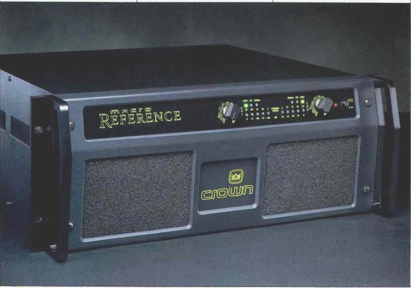
The Macro Reference is a relatively new amplifier from Crown International. Like a number of their other power amps, it is rated at an astonishingly high power output for its size-in this case, 760 watts per channel into 8-ohm loads! A close look reveals a number of very interesting features of this design. And, according to the very complete and informative owner's manual, "Great care has been taken with the routing of each wire, the layout of each circuit board, and the selection of each component. As a result, its sonic integrity is without peer." The manual also talks about the amplifier's large dynamic range, 120 dB between its high power and low noise floor.
Crown also talks about another very practical, real-world matter-dynamic stability, or the lack of spurious oscillations at very high frequencies. The manufacturer points out that quite a few solid-state amplifiers oscillate on parts of the audio signal cycle with some particular loads, and this can cause subtle intermodulation effects. The careful layout in this design is intended to prevent such mischief. A very high damping factor of 20,000 is specified and is said to result in killer bass. Also of note is the use of a tape-wound, low-noise toroidal power transformer with extremely high power density. This must be so if Crown can get this kind of power output from a non-switching amplifier that weighs only 56 1/2 pounds. Of course, the relatively light but quite thermally efficient heat-sinks help here.
An interesting feature is the Input-Output Comparator (IOC) distortion indicator. This circuit continuously compares the input to the output, and a front-panel indicator flashes if these signals differ by more than 0.05%. The Output Device Emulator Protection (ODEP) circuit is surely one of the most intelligent and comprehensive in the industry.
Another useful feature is the provision for installing Programmable Input Processor (P.I.P.) modules. The module normally supplied has no active or special circuitry but adds XLR balanced inputs to the built-in quarter-inch phone jacks, which can be used for balanced or unbalanced input.
Crown offers a number of interesting optional P.I.P. modules, including low-level crossover filters, input isolation transformers, precision attenuators, input limiters, and specialized types for sound reinforcement work.
The styling of this amplifier is rather unique-somehow, it reminds me of a combination of a guitar amp and an old jukebox, but overall, I think it is attractive. On the front surface we find two large air inlet ducts with cleanable filters that take up most of the lower panel area. Along the top of the panel are the back-lit Macro Reference logo, two rotary gain controls with detents, a power switch, and multiple-LED displays for "Dynamic Range," "Signal Present," "IOC," and "ODEP." The five LEDs per channel can be switched to indicate the dynamic range in the program (computed as the ratio of peak to average power) or the output level in decibels relative to full output.
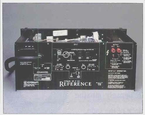
On the rear panel are the signal input and output connections. Signal input connection can be either with XLR or quarter-inch phone plugs, balanced or unbalanced. Output connectors are five-way binding posts; each channel's pair is spaced 3/4 inch away from the other's, so a dual banana plug could be connected between both channels' hot terminals in the bridged mono mode. By the time this review appears, the amp will be fitted with two sets of output binding posts. It will also be available in an Esoteric version, using Cardas output posts and adding RCA phono inputs (switchable between floating balanced or unbalanced operation) on the same module as the XLR jack, plus switches to turn off the display and the front-panel illumination.
Also on the rear panel are a captive power cord, a circuit-breaker "Reset" switch, a "Parallel Mono/Stereo/Bridged Mono" slide switch for operating mode, and a "Ground Lift" slide switch to disconnect signal ground from the a.c. third-wire and chassis grounds. I must give special mention to the power cord, which is wonderfully flexible considering its large diameter and wire gauge.
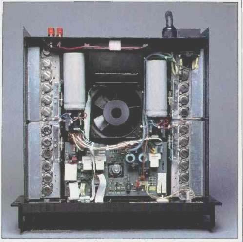
The internal layout is well thought out and executed. On the underside of a horizontal partition plate, about halfway up the interior, are the toroidal power transformer, main circuit board, and output-stage interconnect boards. The transformer is at center right behind the front panel, the main circuit board is at the rear, and the output stage boards run fore and aft along each side. In the center of the plate is the grille for the variable-speed cooling fan. This fan only operates when the ODEP computer determines (by simulating the operating conditions of the output devices and comparing them to the devices' safe operating areas) that the output transistors need cooling. There are also temperature sensors on the heat-sink but just for backup.
Air drawn through the front-panel filter openings enters the lower section of the unit and passes through the fan into the upper section. Mounted on top of the dividing partition are the four output-stage mounting plates with integral dissipating fins, the cooling fan, filter capacitors, bridge rectifiers, a control p.c. board, and the housing and connector for the P.I.P. input module. The level-control potentiometers and the display circuitry are mounted behind the front panel.
The rest of the chassis construction is rather straightforward and consists of separate rear, side, and front panels screwed together. Top and bottom plates are attached by screws through the side and rear panels to bent lips on the top and bottom plates. The unit is neatly wired and has high quality parts. Construction technique is good but not stellar, using machine screws into tapped holes rather than into pressed-in Pemm nuts. The transferrable full warranty is unusually long, six years, and includes round-trip shipping.
Circuit Description
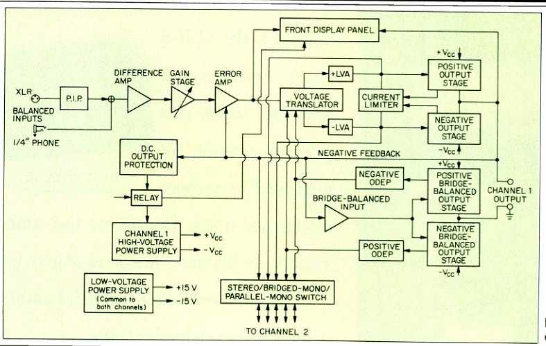
Fig. 1--Block diagram; one channel shown.
The Macro Reference is a relatively complicated piece of gear; a block diagram is shown in Fig. 1. One of the most unusual things is the "grounded bridge" arrangement. Generally, in full-bridge or stereo amplifiers used in bridge mode, the output is taken between the hot terminals of two half-bridge output circuits-either the two stereo output channels or the equivalent two half bridges that make up the usual full-bridge output stage. Two of the problems in the usual bridge arrangement are not being able to use certain servo woofer systems that have velocity bridge-feedback sensing schemes and the general fear of accidentally grounding one side of the output in demonstration switchers or sound systems. Crown introduced this unique topology a number of years ago (I believe in the Model M600). It permitted one output of the bridge to be grounded, thus rendering it possible to bridge these two channels-or "bridge the bridges"-for a really impressive output in ex cess of 1 kW. This newer Macro Reference amplifier can produce about 3 kW of steady-state power into a single 4- or 1-ohm load!
Signal input from the phone jacks or output of whatever P.I.P. module present is fed into an op-amp circuit configured to convert from a unity-gain differential input to a single-ended output. Input and feedback resistors are 5 kilohms, thus setting the unbalanced input impedance to a low (for normal audio use) 5 kilohms and the balanced input impedance to 10 kilohms. This feeds another op-amp circuit set up as a variable-gain, inverting feedback circuit, with a front-panel control varying the gain. A slide switch in the P.I.P. module sets input sensitivity for full output power with front-panel gain controls at 0.775 or 3.9 V rms maximum; the latter corresponds to a voltage gain of 26 dB. I would call this circuitry "front-end signal conditioning." From here, the signal is capacitor-coupled to the amp's first stage, shown in Fig. 1 as the "error amp." This IC opamp is set up in an overall inverting mode but is noninverting as a local circuit and has its own negative feedback loop. Overall low-frequency feedback runs from the output of the following bridge phase, before the output buffering network, back to the error amp's noninverting input; it works against a series resistor fed from the gain-setting stage, which precedes the error amp.
The output of this first stage is fed into a voltage-translation circuit, at last composed of discrete transistors, that couples the op-amp's limited voltage-swing capability to the last voltage amplifier stage ( + LVA and- LVA in Fig. 1).
A high-frequency feedback loop from the output side of the RL output buffering network is capacitor-coupled back into the voltage-translation stage to provide high-frequency feedback that excludes the preceding op-amp stage. This nested feedback-loop structure is quite sophisticated.
The last voltage amplifier stage is a complementary common-emitter circuit with emitter feedback that swings the full output voltage of the amplifier. Following is a triple Darlington-connected, complementary emitter-follower output stage using three pairs of output transistors. This constitutes the main half of the overall bridge output stage.
The other, "bridge-balanced," half consists of a similar output stage with the same number of output transistor pairs, but its function and mode of operation are different.
First of all, its output stage emitters are grounded; thus, the output is taken from the collectors, which are, lo and behold, the power-supply lines for both halves of the bridge! Feed back, taken from each supply rail and from the output of the main amplifier output stages, controls this half of the circuit so that it precisely modulates the supply rails by exactly half of the amplitude of the main amplifier's output voltage. (This is accomplished by another IC op-amp that feeds the input to this triple Darlington "slave" half of the overall grounded bridge output stage.) Instead of the usual bridge circuit, where power-supply rail voltages are fixed and the voltages of both output terminals swing equally in opposite directions, the Crown circuit swings the supply rails, and one output terminal is grounded. This grounding lets you bridge channels together-normally, you can't bridge a bridge. I have always admired this grounded-bridge circuit for its outrageously original and clever concept. Kudos to Gerald Stanley of Crown, who, I believe, invented it.
In the main power supply for the output stage, one unusual feature stands out, the use of one main filter capacitor rather than the usual two. In a grounded-bridge circuit, the high-current secondary winding does not need to be center tapped; thus, only one filter capacitor is needed between positive and negative outputs of the full-wave rectifier bridge. The capacitor value is modest by ultimate amplifier standards, only 6,300 uF, but has a 135-V rating. I still can't figure out how they get so much power out of this relatively small power supply!
Measurements
Frequency response with open-circuit, 8-ohm, and 4-ohm loads is shown in Fig. 2. Response is shown for the left channel, which was down slightly more than the right. If you compare these curves with those for other amplifiers I have reviewed, it will be clear that the Crown's voltage regulation in the audio range portends a very low output impedance because the curves appear as one over most of the audio range. Some out-of-band differences do show up, due to the output buffering RL network used in this and most other solid-state amplifiers.
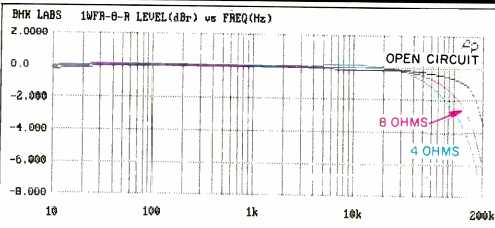
Fig. 2-Frequency response at 1 watt output.
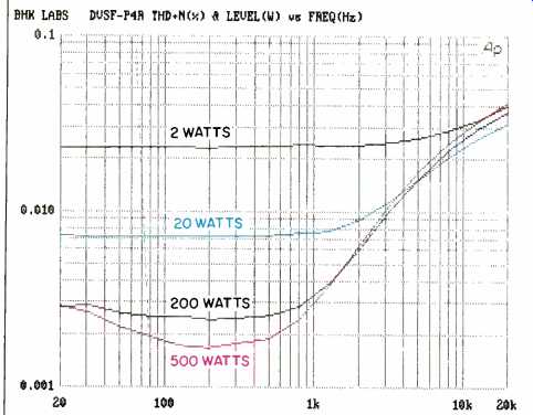
Fig. 3--THD + N vs. frequency, as a function of power into 8-ohm load. The
vertical offshoot of the 500-watt curve is due to action of the amp's protective
circuit; see text.
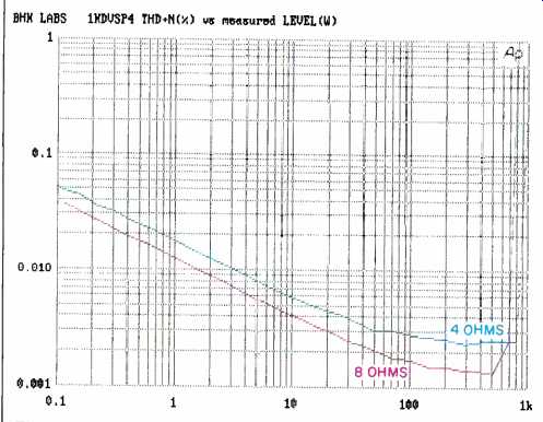
Fig. 4--THD + N vs. power at 1 kHz.
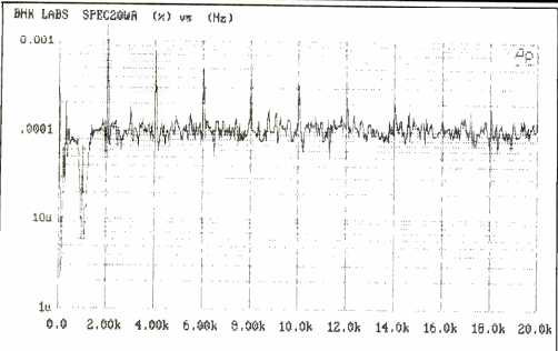
Fig. 5--Distortion spectrum of right channel for 1-kHz signal at 20 watts
into 4-ohm load.
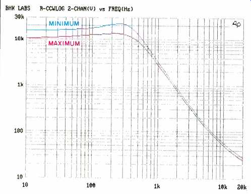
Fig. 6--Damping factor vs. frequency for minimum and maximum settings of
level control.
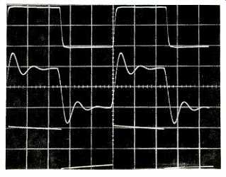
Fig. 7--Square-wave response for 10 kHz into 8 ohms (top), 10 kHz into 8
ohms paralleled by 2µF (middle), and 40 Hz into 8 ohms (bottom). Scales:
Vertical, 5 V/div.; horizontal, 20 RS/div. for 10 kHz, 5 mS/div. for 40 Hz.
Gain and sensitivity were measured with the front-panel gain controls set fully clockwise and with the controls set 14 clicks down from clockwise, about half rotation. Results with controls at maximum were a very high gain of 40 dB for each channel, yielding a sensitivity of 28 mV to produce 1 watt into 8 ohms. With the controls at about half rotation, gain was down to 23.5 and 23.3 dB for the left and right channels, respectively, corresponding to a sensitivity of 189 and 193 mV. With controls set fully counterclockwise, gain was down to about- 56 dB. These tests were done with the sensitivity switch set for maximum gain. When it is set to the other position, voltage gain is 26 dB (not measured) with level controls set to maximum.
Distortion in this amplifier is so low that it was hard to measure, as it is down in the noise over much of the power and frequency ranges. Figure 3 shows THD + N as a function of frequency and power level, for the right channel with a 4-ohm load. The figure mostly shows noise at lower power levels, although at high frequencies we can see the distortion rising out of the noise, even at the low level of 2 watts. Notice that one curve shows an abrupt distortion rise below 100 Hz. This occurred on my second 500-watt power sweep, when the protection circuit came in and caused current limiting on the signal peaks. The cooling fan came on with an impressive roar, but what was even more impressive was how fast it slowed down when the input signal was removed.
Shown in Fig. 4 is 1-kHz THD + N as a function of output power for 8- and 4-ohm loads. (The curves are displaced by a factor of 1.414, because S/N ratios with 4-ohm loading are automatically 3 dB lower.) Only when the downward slopes of the curves begin to change, and eventually turn upward, is real measured distortion seen. A plot of SMPTE-IM distortion (not shown) was similar.
The power levels reached in Fig. 4 are lower than what the Crown can achieve when connected to a true low-impedance a.c. line, which I don't really have in my lab. In the case of the Macro Reference, I had my 25-ampere Variac cranked wide open when the power was approaching maxi mum and the measured line voltage at the end of a 4-ohm power sweep had sagged to about 110 or 112 V. A spectral plot of the right channel's harmonic distortion residue at 20 watts output into a 4-ohm load (Fig. 5) shows that the distortion is dominantly even-order. Dominant even-order distortion frequently is relatively constant with increasing power output. This proved to be true over a wide power and frequency range.
Interchannel tracking of the gain control was found to be within 1.2 dB down to-50 dB and within 4 dB at an attenuation of 70 dB. This is quite good over a large range of 50 dB.
Interchannel crosstalk versus frequency, with the front panel level controls at maximum, was found to be down about 100 dB to about 200 Hz; it then rose at 6 dB per octave to a level of about -62 dB at 20 kHz. With the controls set to about half rotation, crosstalk was again about 100 dB down, this time staying there to about 1 kHz before rising with frequency. At 20 kHz, crosstalk was about -75 dB. The results were very similar for left-to-right and right-to left measurements.
Damping factor as a function of frequency, with the level control at its minimum and maximum, is shown in Fig. 6 for the right channel, which had the higher damping factor. I have never encountered such a low output impedance in an amplifier before! When I injected a constant current of 1 ampere into the channel being measured, the voltage across the undriven channel was less than 1 mV from 10 to 500 Hz! Damping factor decreased above about 500 Hz due to the impedance of the output RL buffering network (and probably a decreasing amount of feedback for in creasing frequencies, borne out by the rise in THD), but note that the damping factor is greater than 20 at 20 kHz.
Rise- and fall-times for 8-ohm loads at an output level of ±5 V were about 2.4 uS, both at full level and with level controls at half rotation. For 4-ohm loads, rise- and fall-times lengthened to about 3.2 uS. Figure 7 shows the amp's square-wave response. The top trace is at 10 kHz with 8-ohm loading. With a 2-µF capacitor in parallel with the 8 ohm load (middle), we see ringing caused by the output buffering RL network. The 40-Hz wave in the bottom trace displays satisfactorily low tilt.
Noise levels (Table I) are impressively low, and no a.c. line harmonics were visible in the noise residuals on my 'scope. Note the similarity between the readings for band widths of 22 Hz to 22 kHz and 400 Hz to 22 kHz.
In the test of IHF dynamic headroom, I got a prodigious ± 120 V, peak, into 8-ohm loads, for an equivalent rms power level of 900 watts and dynamic headroom of 0.7 dB.
With 4-ohm loads, I got equivalent figures of 1,500 watts and 1.1 dB. These values are undoubtedly low, due to my a.c. power line's impedance, but are nonetheless most impressive! Power-line considerations prevented measurement of clipping headroom and any attempt to measure maximum attainable current into a 1-ohm load. As a final measurement note, the amplifier's a.c. line draw at idle was about 700 mA.
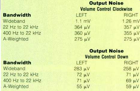
Table I--Output noise, with volume control fully clockwise and at approximate
halfway point (14 detents down). The A-weighted S/N ratio was 96 dB for either
channel.
Use and Listening Tests
Equipment used to evaluate the Macro Reference included as signal sources an Oracle turntable fitted with a Well Tempered Arm and Spectral Audio MCR-1 Select cartridge, a Krell MD-1 CD transport feeding a VTL Straight Line D/A converter, a Nakamichi 250 cassette deck and ST-7 tuner, and a Technics 1500 open-reel recorder. Preamplification for records was supplied by my reference tube phono preamp. Additional preamps used were a First Sound Reference II, an Acurus L10, and a Quicksilver Audio. Other power amplifiers on hand during the review period were a pair of Carver Silver Sevens, Quicksilver Audio M135 prototypes, a prototype digital switching amplifier, and a McIntosh MC2600. Loudspeakers used were Win Research SM 10 monitors and Spica Angelus systems.
My first listening impressions of the Crown amplifier were:
Wow! This is the best Crown amplifier that I have ever heard! Overall frequency balance seemed just a little thin in the lower midrange, but I had grown accustomed to the tube amplifiers I use, which tend to be stronger in this region. The Crown's space and resolution were extremely good. Bass was indeed beautifully tight and defined. Over all dynamics were just as effortless as you'd expect from such large power reserves. When I used the Acurus line-level preamp, the sound got a bit congested and irritating when it got loud.
Overall, best sound was obtained using the First Sound passive preamp with its level controls set to about half rotation and the level controls on the Macro Reference controlling overall volume. I sure did get the feeling of more accuracy than usual in a lot of my listening with the Macro Reference, although I didn't always completely like the results with certain software that also tends to be irritating through other component combinations. I have heard that other reviewers have been comparing the Macro Reference to some of the big names in solid-state amplification and that the Crown has been judged to be superior in a number of instances. When considering its price, which is really very reasonable for the performance obtained, I give this amp a most enthusiastic thumbs up! I may just buy this honey.
-Bascom H. King
(Source: Audio magazine, Jun. 1992)
Also see:
Crown Power Line Four Amplifier (Apr. 1983)
Crown FM Two Tuner (Apr. 1982)
Counterpoint SA-220 Power Amp (Jul. 1990)
Conrad Johnson Premier Five Amplifier (Aug. 1986)
= = = =