MANUFACTURER'S SPECIFICATIONS
FM TUNER SECTION.
IHF Sensitivity. 2.0 µV. S/N Ratio: 60 dB. THD (Mono): 0.3%. Selectivity: 55 dB. Capture Ratio: 1.5 dB. Image Rejection: 78dB. Stereo FM Separation: 35 dB.
AM TUNER SECTION.
IHF Sensitivity: 7µV. Selectivity: 23 dB. S/N Ratio: 50 dB. Image Rejection: 45 dB.
AMPLIFIER SECTION.
Power Output: 36 watts/channel, 8 ohm loads.
Rated THD: 1.0%. Power Bandwidth: 18 Hz to 45,000 Hz. Frequency Response: 20 Hz to 30,000 Hz (No tolerance given). Input Impedance, Phono, Aux, Tape: 50 K ohms. Input Sensitivity: Phono, High: 5.0 mV; Low: 2.5 mV. Aux: 200 mV; Tape: Adjustable from 0.2 to 2.0 volts. Tone Control Range: Bass: ± 12 dB @ 100 Hz; Treble: ± 12 dB @ 10,000 Hz; Mid-Range: ±dB @ 1500 Hz.
GENERAL SPECIFICATIONS.
Power Requirements: 120 V, a.c., 60 Hz (40 to 400 W. Max).
Dimensions: 18 3/8 in. w. x 5 1/2 in. h. x 18 in. d.
Retail Price: $598.00 including wood cabinet and separate remote control unit.
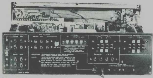
Fig. 1--Rear
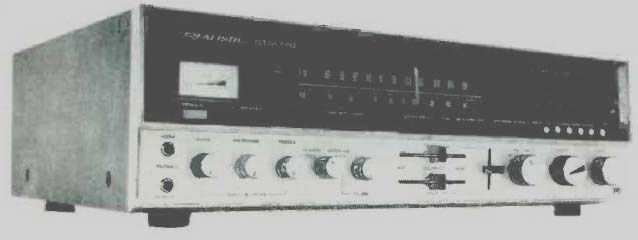
The roster of four-channel receivers keeps growing, and this Realistic Model (produced for and sold by the Radio Shack stores around the country) does offer a great deal for its price. We are a bit distressed, however, by some of the verbiage employed by this company in promoting their product--as reflected in their advertising literature and in the owner's manual that comes with this basically fine product. The manual notes that they do not rely "on the usual confusing array of Manufacturer's Specifications, most of which are, sad to say, irresponsible," but then, on the very next page, they list quite an impressive array of their own "manufacturer's specifications" and include a power output spec of "280 watts total ± 1 dB"! Come, now, gentlemen, you've got a good receiver here that produces an honest 35 watts per channel of continuous audio power with all four channels going at once--and that totals 140 good clean watts (against the 144 you claim for the "continuous" power rating) of power. If you really believe that most published specs are "misleading" and shouldn't be relied upon, how about dropping that misleading " 1 dB," as most of your competitors have done! The QTA-790 is a handsomely designed big receiver, as can be seen in the front panel photo. The panel itself is made of a single solid casting, with a blackout plastic insert at the top, a brushed-gold aluminum panel below, and polished gold-colored framing around the entire perimeter. The blacked out portion contains a signal-strength meter, a dial scale for AM and FM frequencies, a softly illuminated dial pointer and five small vertically calibrated dials which are used to pre-select favorite FM stations by means of combination rotate/push buttons located directly below the five dials. Below the dial scale, but still in the black portion of the panel, are power ON/OFF pushbutton, SPEAKER A/ SPEAKER B buttons, tape monitor button, MONO/STEREO selector button, filter buttons (HIGH and Low), mute ON/OFF button, an AFC ON/OFF button, a loudness control ON/OFF button, and a manual tune and "remote" button. The lower portion of the panel includes dual headphone jacks (for four-channel headphone connection), dual concentric clutch-type bass, treble and mid-range tone controls, a mode switch for selecting STEREO (front channels only), SQ MATRIX (for SQ or other types of matrix recordings and FM broadcasts) STEREO ALL (two-channel material fed to front and rear speakers) and Aux 4 (discrete four-channel inputs such as tape or the outputs of a "discrete" Quadradisc demodulator). A separate volume control for these Aux 4 inputs is provided and works independently from the master volume control located further to the right. Three slide-controls provide all the "balancing" facilities one would need in a four-channel setup. The two horizontally sliding controls provide left-right balance for either front or rear channels, while the vertical sliding control balances front levels against rear--rather a nice arrangement for that. The program selector comes next, offering positions for AM, FM, PHONO and Aux. The Aux position offered here is an additional stereo Aux position over and above the four-channel Aux inputs previously mentioned. The master volume control comes next, followed by a tuning knob which is not flywheel coupled for reasons which will become clear in a moment.
At the upper right of the panel is a small concave depression covered with fine metallic grill material. This permits supersonic tones from the remote control unit to impinge upon the rear-mounted transducer (microphone) which is connected to the "remote control receiver" to be discussed later.
The rear panel, shown pictorially in Fig. I, has almost as many interesting features as the impressive front panel. There are two-channel phono and aux inputs, with a slide switch to select high and low sensitivities for different types of phono cartridges. There are the four "discrete" aux inputs for four-channel program sources from tape, as mentioned. In addition to the usual "tape out" and "tape in" pairs of jacks, there is a pair called "dub out" which permit recording from one tape recorder to another or recording from a program source selected within the receiver (AM, FM or phono or aux) onto two tape recorders simultaneously. The tape playback input jacks have an input level control associated with them, to compensate for the widely differing line output levels which exist between commercially available reel-to-reel, 8-track and cassette machines these days. Screw terminals are provided for external AM antenna, 300 ohm or 75 ohm FM antennas.
The line cord of the QTA-790 is equipped with a metal clamp which acts as a small capacitor if connected to the FM antenna center terminal, thus utilizing the length of the line cord (plus who knows how many unmatched yards of house wiring) as an "FM Antenna." We promptly disconnected this clamp and connected a legitimate antenna for our listening tests after measurements were completed. Speaker terminals for up to eight speakers (two full sets of quadraphonic systems) are of the very practical and easy-to-use "piano key" type which, when depressed, disclose a small hole into which the stripped ends of your speaker wires are simply inserted. Letting go of the "keys" clamps the wires firmly in place and, if you don't strip away too much insulation, this arrangement absolutely precludes the possibility of speaker cable shorts. (If you do strip away too much insulation, just snip off the exposed copper wire to about 1/8 inch of length and the system works perfectly.) Just in case you happen to own speakers equipped with pin-plug connectors, four jacks, paralleling the "A Speaker" terminals are also provided below the speaker terminals. Two unswitched convenience a.c. receptacles and a holder for 3 ampere fuses complete the back-panel layout.
Considering the enormous amount of circuitry contained in the QTA-790 receiver, the chassis layout is neat and very well laid out.
There are 12 separate modules used to make up the circuitry of this receiver, some of which can be seen in the photo of Fig. 2. The FM front-end, manufactured by Alps, is about the smallest we have seen, largely because it does not contain a variable capacitor. All FM tuning is accomplished electronically, by applying well regulated d.c. voltages to varactor diodes. Each of the station pre-sets referred to earlier is, therefore, actually nothing more than a multi-turn potentiometer which "picks off" a selected amount of d.c. voltage and "tunes" the front-end to the desired frequency. Even the manual tuning knob is simply geared down to a single turn potentiometer which "scans" voltages required to tune from 88 MHz to 108 MHz, and therefore no flywheel was used in the arrangement.
The small front-end is mounted directly on a large "tuner board" module which includes a two-gang AM variable capacitor and a minimal amount of AM circuitry. The FM i.f. section is quite elaborate, however, and includes a permanently tuned ceramic filter, three interstage transformers, three transistors, an integrated circuit, and a conventional ratio-detector circuit. The FM stereo circuitry is also contained on this module and utilizes a 4-diode bridge in its time-division demodulation circuit. The SQ decoder board is of interest in that it utilizes a total of 15 transistors to accomplish the necessary phase-shifting, summing, and decoding required in the SQ system. The phono pre amp module contains four transistors, two per each channel of equalization and preamplification. Two channels of power amplification are mounted on each of two power output modules, attached to fairly massive, sturdily mounted heat sinks, each of which houses four 2SC 1 111 power output silicon transistors in TO-3 housings. Other modules examined include a separate tone-control module (four two-transistor negative-feedback Baxandall circuits), a power supply module, a remote control receiver module (no less than 21 transistors required on this one), a pre-set remote control module (ten more transistors, 3 IC's and five relay-switches) plus several other minor modules for voltage amplification, dial pointer illumination, and circuit protection. In all, we counted no less than 103 transistors, not including the two used in the separate remote control hand-held unit.
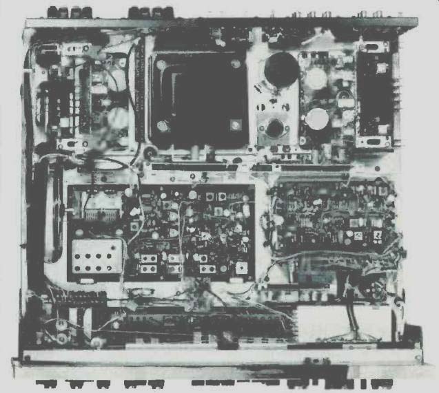
Fig. 2--Inside view of chassis layout.
Laboratory Measurements
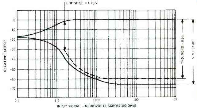
Fig. 3--Mono FM characteristics.
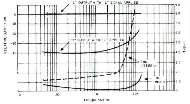
Fig. 4--Distortion and separation characteristics.
Important monophonic performance characteristics are plotted in Fig. 3. IHF sensitivity turned out to be 1.7 µV, quite a bit better than the nominal 2.0 µV claimed by the manufacturer. More important, 50 dB of SN was attained with a mere 3 µV of signal input, an extremely impressive figure.
Ultimate S/N was 67 dB, achieved for all input levels above 50 µV, and again, much better than the 60 dB claimed for the FM section. THD in mono reached an incredibly low 0.1% for 100% modulation. This is as low as we have ever measured and corresponds to the guarantee provided for our excellent Sound Technology FM Stereo Generator. The manufacturer only claims 0.3% for this specification and possibly they have no way to measure the low figure actually realized by the receiver. A complete plot of THD versus frequency is shown in Fig. 4. Although mono THD does rise a bit at the extremes of the audio range, it remains comfortably below 1.0% to 10 kHz and reaches no higher than 0.5% at the low end of the audio spectrum. However, in stereo mode the THD is not as good, hovering at about 1.5% at mid-band and low frequencies and climbing above the 2% mark for frequencies above 5 kHz.
The distortion content at these high frequencies was both harmonic and "beat frequency" in nature, with the latter contribution rising as higher frequencies were tested. Under music listening conditions, this "beat" contribution is less offensive than the purely harmonic contribution and, therefore, the amount measured at 10 kHz, for example, is not nearly as "audible" a distortion as you might suppose.
Stereo separation at low and mid frequencies was 40 dB, much better than the 35 dB claimed, decreasing to about 25 dB at 10 kHz. Both left and right channels behaved similarly in this respect, and so only the right output is plotted in Fig. 4 for separation characteristics.
By our measurements, the QTA-790 is capable of producing 35 watts per channel at a THD of 1% or less, measured at 1000 Hz. These measurements were made with all four channels driven to full output, and is certainly close enough to the 36 watts claimed by the manufacturer--since one meter needle "pointer width" would account for such a small difference.
THD versus power output is plotted in Fig 5, and for all power levels below 25 watts or so, THD hovers around a very low 0.1%. IM distortion, also shown in Fig. 5, is about 0.2% for all power levels below 20 watts and reaches 1% for an output of about 28 watts per channel. At 32 watts per channel, IM reached 3.0%. Although the manufacturer makes no claims for wattage output capability at the extremes of the audible frequency range, it is clear from Fig. 6 that the 35 watt power figure is a mid-band capability. At half rated power, the THD remained below 0.5% across the entire audio band, while at 1 watt nominal listening levels, the 0.1% or better figure applied across the entire audio spectrum.
Power bandwidth, shown plotted in Fig. 7, turned out to be from 18 Hz to 45 kHz, exactly as claimed.
Other data relating to both r.f. and audio performance were taken, though not specifically plotted in graph form.
These include a capture ratio of 1.5 dB as claimed, selectivity of 58 dB (somewhat better than claimed), and confirmation of the various input sensitivity specifications stated by the manufacturer.
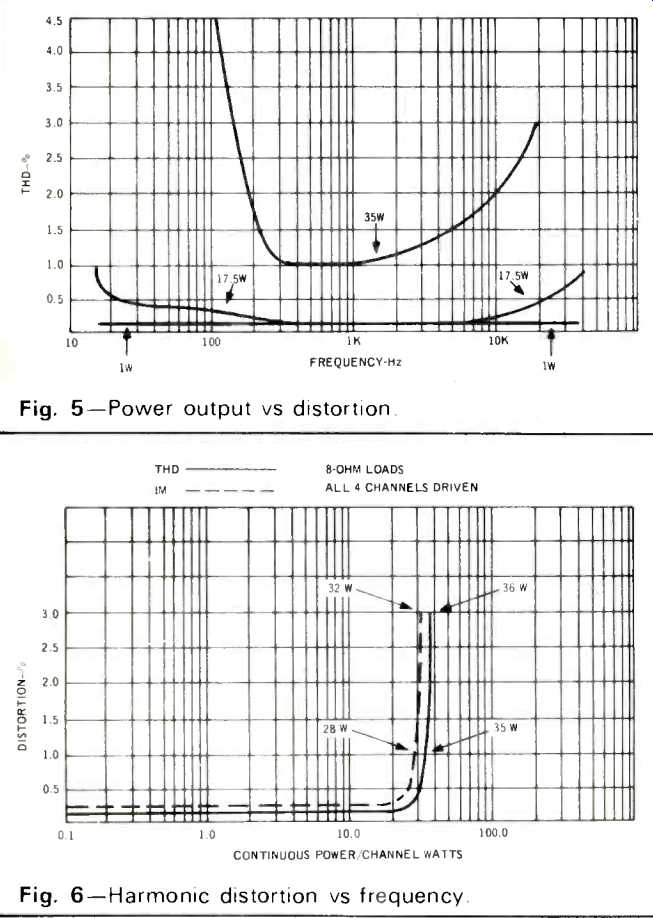
Fig. 5-Power output vs distortion. Fig.
6-Harmonic distortion vs frequency.
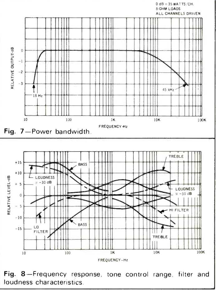
Fig. 7-Power bandwidth.
Fig.
8--Frequency response, tone control range, filter and loudness characteristics.
Phono hum level, though not stated by the manufacturer, is one specification they should have been proud to publish. It measured 68 dB below rated input signal in the "high" sensitivity position and 72 dB in the "low" setting. Aux hum for rated output with rated input was about 75 dB, while amplifier residual hum (volume at minimum) measured about 80 dB. Other preamp-control characteristics are plotted in Fig. 8.
These include plots of the three tone controls. Of particular interest is the range of the "mid-range" control, that third control lately being added by several receiver and amplifier manufacturers. It acts much like a "presence" control, emphasizing voice frequencies and, while we feel that in the case of the QTA-790 its mid-point of action is a bit high in frequency (it centered at about 1500 Hz), it is most effective in use and well worth having. Loudness, high and low filter action were typical (filters had a slope of 6 dB per octave), and the designers of this equipment chose to include a moderate amount of treble emphasis in their loudness circuit, as well as the usual bass-lift with decreasing volume settings.
Remote Control Unit
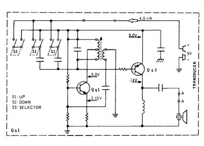
Fig. 9--Schematic diagram of battery-powered remote control unit.
Before commenting upon our listening experience with the QTA-790, a brief description of the included remote control unit would be appropriate. When first confronted with this "extra" we presumed that it would perform the same "station scanning" function performed by other "remote control" units we had seen. Well, it does select stations, but only those you've selected on the five pre-set dials, and actually, that's really quite sufficient. What we really had hoped for in a remote control unit was a means of controlling volume level.
Sure enough, this one has it. In addition to the station selector button (which, when pushed, successively chooses pre-sets one through five), there is an "up" button and a "down" button. When these are pushed, the entire volume control on the receiver actually rotates clockwise or counterclockwise--slow enough for you to "zero in" on just the volume level you want. A geared-down miniature motor is actually coupled to the volume control shaft within the receiver and the motor is actuated by part of the 21-transistor "remote control module" we mentioned earlier.
A schematic of the hand-held "transmitter section," which is powered by a standard 9-volt "transistor" battery, is shown in Fig. 9 and, as you can see, the three switches or buttons simply actuate an ultra-sonic oscillator at three predetermined frequencies. The output of the electronics drives a transducer (think of it as a super-super-tweeter, if you like), whose sonic energy is picked up by the "microphone" transducer mounted on the front panel of the receiver. Sounds simple, of course, but it meant quite a bit of additional electronics in this already "full" receiver. All-in-all, the remote feature was very well executed, and we used it for nearly a week in our listening tests and neither it, nor the receiver, ever "did the wrong thing."
Listening Tests
Much of our listening with this receiver was devoted to SQ encoded records, since this is, after all, a four-channel receiver. SQ decoding was fine, but of course only the basic SQ matrix decoding is used, with no "logic circuitry" provided.
As is true with all previously SQ products tested, effective four-channel spatial distribution under these circumstances is highly dependent upon proper listener position.
In our opinion, the SQ matrix is not particularly effective in "synthesizing" four-channel effects from older two-channel discs, though of course some ambience is recovered in this format. We would have preferred to see a second "matrix" position available for such playing, as well as for more effective reproduction of other matrix-type discs such as QS or "regular matrix." The muting circuitry of the FM section is set to about 7 microvolts threshold, which in itself is not an unwise choice.
However, the transition from mute to non-mute is not quite instantaneous and, in listening to FM, we were able to encounter situations that were "borderline" and tended to "confuse the muting circuit." Disabling the mute button corrected these few situations, however. Stereo threshold, on the other hand, is set at about 5 µV, and is quite positive in its action.
Signals below that input level would not be satisfactory if heard in stereo, and the action is automatic in restoring mono reception under those circumstances.
FM mono performance was without any flaws, but we were slightly conscious of distortion when listening to stereo FM stations. Frequency calibration was a bit off (about 500 kHz at the low end, about 150 kHz at the high end) on the unit we tested, but this could no doubt be easily corrected by more careful alignment of the electronic voltage-tuning circuitry.
Sensitivity was excellent not only at mid-band, but at all points on the FM dial, as evidenced by the 54 signals we were able to pick up with our stationary outdoor Yagi antenna directed towards New York City some 20 miles away.
We found that amplifier power capability was adequate for driving our low-efficiency, air-suspension speaker systems to loud listening levels, but at really ear-shattering levels, bass overload was detected on some passages of rock recordings we used for our auditioning. Unless you are equipped for four-channel sound (and have four speakers in your listening room), stereo operation of this receiver limits its use to two of its four 35 watt channels. On the other hand, if you do have four speakers in your room but choose the STEREO ALL position of the mode switch, that effectively adds 6 dB of sound-pressure level to your overall sound, even when stereo program sources are used. Certainly, if four-channel material is used (either matrix or discrete), 36 watts per channel times four seemed to us like more than enough for our "average" size living room (14 x 19 feet).
Certainly, the complexity possible in a four-channel receiver goes beyond that designed into this Realistic Model QTA-790. On the other hand, so do some of the prices for these four-channel all-in-ones. All things considered, at $598.00 this receiver manages to provide many of the goodies the budding four-channel enthusiast is likely to look for-and is likely to be able to afford.
-Leonard Feldman
(Adaped from Audio magazine, Jul. 1973)
Also see:
Realistic (Radio Shack) Model STA-225 AM/FM Stereo Receiver (Equip. Profile, Dec. 1975)
Realistic (Radio Shack) STA-120B AM /Stereo FM Receiver (Dec. 1972)
Scott Model R-376 AM/FM Stereo Receiver (Equip. Profile, June 1977)
= = = =