MANUFACTURER'S SPECIFICATIONS
FM Section
IHF Sensitivity: 1.9 µV. S/N Ratio: 65 dB.
Capture Ratio: 1.2 dB.
THD: Mono, 0.6%; Stereo, 0.8%.
Image Rejection: 70 dB.
AM Section
Sensitivity: 250 µV/M, internal antenna. Image Rejection: 55 dB.
Amplifier Section
Power Output: 50 watts per channel into 8 ohms from 20 Hz to 20 kHz (continuous); THD over entire power band, no more than 1.0%. IM Distortion: Less than 0.6%. S/N: Phono, 60 dB; Aux, 70 dB. General Specifications
Dimensions: 19-1/8 in. W x 5-3/4 in. H x 15 in. D.
Price: $399.95.
There is a good deal to commend in this Realistic stereo receiver distributed by Radio Shack stores, but at the same time we surely would like to have seen Radio Shack give more than a minimum number of specifications. After all, not every prospective buyer gets a chance to read an equipment profile in Audio to find out what phono cartridge output matches up best or what the input sensitivities of the AUX and Tape Inputs are. With too many other firms, such a scarcity of specs suggest poor performance, yet in This case Radio Shack is hiding its light under a bushel since the parameters we measured turned out too good to hide.
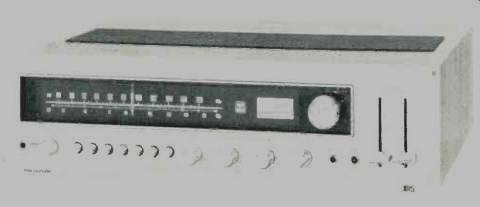
The STA-225's front panel has the now-familiar long, black-out dial area, which occupies all but a couple of inches of the panel. When illuminated, the dial area displays a linear FM frequency scale, a 0-100 logging or reference scale, and an AM frequency scale. To the right is a single signal-strength meter, adjacent to which are the illuminated words "Auto Magic" about which we will speak shortly. A good sized tuning knob is located within the blacked-out dial area as well. Two slide controls at the extreme right operate vertically to control volume level for each channel, thereby eliminating the need for a separate balance control.
If input program sources are balanced, the two sliders can be operated in unison with a single finger-a nice touch that works as well in practice as in theory.
Below the dial scale area are a phone jack (at the extreme left), seven small push-buttons; dual-concentric clutch-type bass, mid-range, and treble controls; a program selector switch; a dubbing-out jack, and a tape input jack (these are in addition to the usual tape monitoring in and out jacks on the rear panel). A speaker selector switch also turns on power, selects main or remote speakers, or chooses Radio Shack's "Quatravox" passive decoder circuit which synthesizes a four-channel effect from two-channel sources and is not unlike the Dynaco matrix introduced during the earliest days of four-channel excitement.
Those seven push buttons mentioned above take care of such things as switching on the Auto-Magic feature, introducing low and high filter circuits (at a 6 dB/octave slope rate), activating the tape monitor circuitry associated with the rear panel tape jacks (to gain access to the Tape 2 front panel jack, the main program selector must be switched to the Tape 2 position), loudness circuit activation, mono stereo switching, and tone control bypass or defeat.
The rear panel of the STA-225 has screw-terminals for connection of two pairs of speakers, with pin-jacks paralleling the "main" speaker terminals in case your speaker systems come equipped with cables and built-in phono plugs. Antenna screw terminals are provided for 75-ohm, 300-ohm, and external AM antenna connections, and would you believe that this $400.00 receiver has one of those "capacitor clips" that couples the line cord to one of the 300 ohm terminals to serve as an indoor FM antenna? Since this rather minimal antenna arrangement does a poor job of rejecting multipath, we disconnected the clip for our tests and connected an outdoor FM antenna. Tape out and in jacks, AUX inputs, and phono input jacks are arranged between the speaker terminals and the antenna connections, and a switch near the phono jacks selects high and low input sensitivity. The rear panel also has a pair of a.c. convenience outlets, a line fuse, and a pivotable ferrite bar AM antenna.
The rear panel is shown in the photo of Fig. 1.
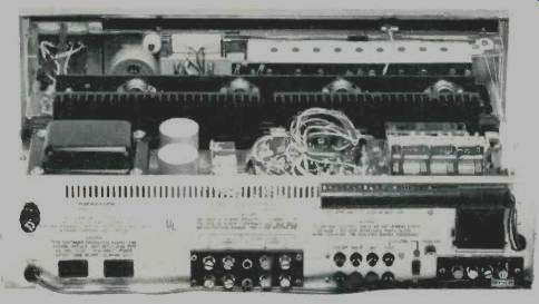
Fig. 1--Rear panel.
Circuit Features
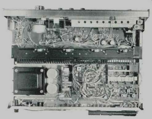
Fig. 2--Interior view.
The chassis layout and circuitry of the STA-225 is shown in Fig. 2. All tuner parts, including the AM and FM stereo decoder sections, are contained on a single large PC board.
The other three major PC modules contain the preamplifiers, the tone control circuitry, and the main power amplifier circuits. The FM front-end is equipped with a four gang tuning capacitor, an FET r.f. amplifier, and bi-polar oscillator and mixer stages. FM i.f. circuitry includes four IC stages (each tuned to 10.7 MHz with a ceramic filter between stages), a bi-polar input stage; and a conventional ratio detector. Multiplex decoding is accomplished by a single IC which utilizes the well accepted phase-lock loop approach to stereo demodulation. Several additional stages are employed in connection with the aforementioned Auto Magic feature of this tuner section. When the user touches the tuning knob, an a.f.c. circuit is defeated, enabling you to accurately tune in desired FM stations (by ear, since the tuning meter acts only as a signal-strength meter). Releasing the tuning knob turns on the a.f.c., which then "pulls in" to center of channel, according to the instruction booklet.
While we generally do not favor a.f.c. circuits, we must comment that during our distortion measurements, we weren't able to improve upon the "lock in" of this circuitry, which did home in on the minimum distortion point of received (or generated) signals. We found, too, that unlike less sophisticated a.f.c. circuits, the presence of this circuit did not prevent us from tuning to weak stations which were fairly close to strong ones. Obviously, not all a.f.c. circuits are alike, and the one in the STA-225 is worth having.
Preamplifier-equalizer circuitry uses discrete devices (two per channel), and the tone controls are of the conventional feedback type. We were delighted to note that each of the slide-volume controls contains two potentiometers-one just ahead of the tone control-circuitry, the other at the input to the power amplifier section. This arrangement makes for best signal-to-noise at any listening level. The main power amplifier circuits feature direct coupling from input to output, a differential input stage, and complementary symmetry output stages. Also included is automatic circuit protection/amplifier shut-down circuitry which will trip if the amplifier is overdriven into too low a speaker impedance.
Tuner Measurements
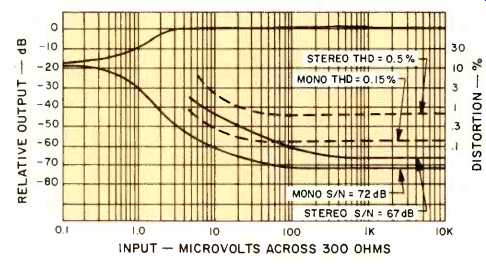
Fig. 3--FM quieting and distortion characteristics.
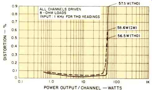
Fig. 4--Separation and distortion versus frequency.
Major tuner performance curves are shown in Fig. 3. IHF sensitivity in mono measured 2.6 µV (equivalent to 13.7 dBf), while in stereo, usable sensitivity measured 6.0 µV, or 20.9 dBf. The 50 dB quieting peak in mono was attained with a signal input of 3.0 µV (14.93 dBf), while in stereo the same level of quieting was reached with a signal strength of 24 µV (33 dBf). Ultimate S/N in mono was 72 dB, while in stereo, maximum quieting measured 67 dB. Mono THD measured a low 0.15%, but was 0.5% in stereo for the same 1 kHz audio signal at full modulation. Capture ratio measured 1.5 dB, while selectivity (alternate channel) was 70 dB as claimed.
Image rejection was 73 dB, a bit better than claimed. Muting threshold (which is not adjustable by the user) was a bit higher than we deemed necessary, allowing signals to break through at levels of 10 µV (25.4 dBf). Stereo switching occurs at signal inputs of 6.0 µV (20.9 dBf) or higher--a well chosen threshold that corresponds exactly to the signal strength required to obtain usable stereo sensitivity.
As shown in the graph of Fig. 4, stereo separation was in excess of 40 dB from 50 Hz to 2 kHz, decreasing to 28 dB at 10 kHz. Distortion at frequencies other than mid-band are also shown in this graph.
Amplifier Measurements
At mid-frequencies, the STA-225 delivered 57.3 watts for its rated harmonic distortion of 1.0%. At rated output (50 watts per channel), a 1 kHz output signal contained only 0.147% THD and IM measured 0.33% for this same output level. The rated 0.6% IM was reached at a power output level of 58.6 watts. At all lower output levels, THD and IM were both well below the 0.1% mark, as shown in the curves of Fig. 5.
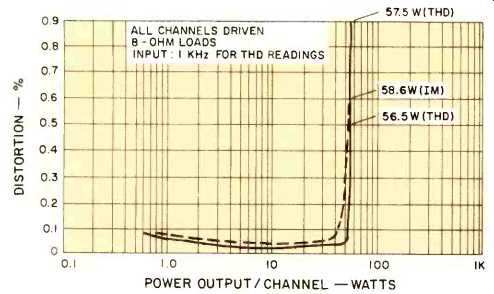
Fig. 5--Harmonic and intermodulation distortion versus power output.
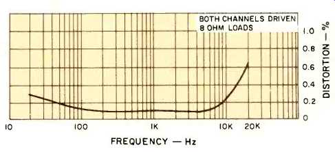
Fig. 6--THD versus frequency.
Distortion was well within FTC limits over the entire frequency band, measuring 0.3% at 20 Hz and 0.63 at 20 kHz. In order to meet claims, the unit could have had as much as 1.0% THD at either of those two frequency extremes, and is therefore conservatively rated by any standards as far as audio power output is concerned. A plot of distortion versus frequency for full rated (50 watt) output is shown in Fig. 6.
Phono input sensitivity measured 1.5 mV in the "high sensitivity" position of the phono rear panel switch and 2.5 mV in the "low" setting. Overload of phono inputs took place with signal inputs of 180 mV or 90 mV, again depending upon the setting of the phono sensitivity switch. Hum and noise was generally much better than claimed, measuring 67 dB for phono (referred to the 2.5 millivolt input sensitivity and full output) and 76 dB in the high-level AUX setting. Input sensitivity for the AUX input measured 200 mV for full rated output. At minimum volume control settings, residual hum measured 102 dB below full output. Overall frequency response of the amplifier section was flat within 1 dB from 20 Hz to 20,000 Hz.
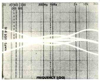
Fig. 7--Bass, midrange,
and treble control range shown on spectrum analyzer sweep display. (Scale:
10 dB per vertical division.)
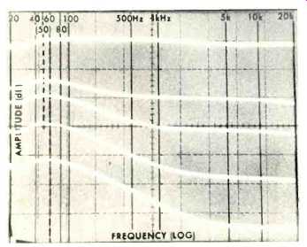
Fig. 8--Action of loudness control shown on spectrum analyzer sweep display.
(Scale: 10 dB per vertical division.)
Having recently acquired a spectrum analyzer in our laboratory, we decided to display tone control characteristics "live" instead of plotting them on graph paper. The photo of Fig. 7 is a composite, taken by producing sequential frequency sweeps from 20 Hz to 20,000 Hz. Each sweep is retained on a storage oscilloscope so that by successively boosting and cutting the bass, treble, and mid-range controls on the Realistic STA-225, we were able to assemble this composite display and record it photographically. Beats pushing a pencil on graph paper anytime, and it's far more accurate since every point is shown, instead of the relatively few points we usually take to plot a "continuous" pencil curve.
Inspired by the results (you may expect to see much more sophisticated applications of spectrum analysis in future test reports, including analysis of the spectral content of harmonic distortion), we decided to "plot" the action of the loudness circuit on our rather expensive version of an "etch-a-sketch" toy and the results, for reader's amazement and amusement, are shown in the 'scope photo of Fig. 8. As you can see, the loudness circuit is continuously variable, but what isn't readily apparent is that the circuit is tied in through the volume controls-an interesting arrangement.
Listening and Use Tests
Getting back to the STA-225, we hooked it up to a pair of low-efficiency, air-suspension speakers and put it through its paces. FM performance was quite good and, if you were wondering about the absence of a stereo indicator light, rest assured it was not forgotten. The dial pointer itself changes color (it glows a bright red) whenever a stereo signal is intercepted on the FM dial. Controls are easy to use and good to the touch, particularly those dual slide volume controls. The mid-range tone control is a useful feature usually found only on separate preamps and amps or much more expensive receivers. Sometimes called a "presence" control (because it can be used to enhance vocalist's sounds and to "bring the vocalist forward" in the stereo sound field), its range in The STA-225 is just right for its intended purpose--about +5 or +6 dB at maximum rotation.
After satisfying ourselves that the STA-225 performed well with our test speakers and a variety of program sources, we attached two more speakers and switched to the Quatravox mode. Depending upon the recordings used, synthesized four-channel effects ranged from barely audible to highly pronounced. Certainly, this circuit isn't intended to substitute for true four-channel but it is of some interest, especially if you own a large record collection and have some discs with sufficient out-of-phase "ambience" information to show off the passive circuit to its best advantage.
In summary, the Realistic STA-225 offers a great deal of value for its modest (these days) price of under $400.00. Power output is solid all the way down to the nether-bass regions, and there was no evidence of excessive heat at the output stages even after several hours of use at loud volume levels. Perhaps Radio Shack is right in promoting the receiver for the more casual user by omitting some important specs and treating the connection panel in a "compact system" way, but we think the audio enthusiast seeking 50 watts per channel has graduated from that level and expects a more audiophilic approach to product presentation.
When it comes right down to it, the STA-225 is just too good for anything less than an enthusiastic treatment from its makers and distributors.
-Leonard Feldman
(Adaped from Audio magazine, Dec. 1975)
Also see:
Realistic Model STA-2200 Stereo FM/AM Receiver (Feb. 1981)
Realistic (Radio Shack) STA-120B AM /Stereo FM Receiver (Dec. 1972)
Realistic Model SCT-30 Cassette Deck (Jun. 1979)
= = = =