Manufacturer's Specifications:
Power Output: 100 watts per channel, 8-ohm loads, 20 Hz to 20 kHz; 105 watts at 1 kHz.
Rated THD: 0.005 percent.
SMPTE IMD: 0.002 percent.
Frequency Response: High level, d.c. to 200 kHz, +0, -3.0 dB; phono, RIAA, ±0.2 dB.
Damping Factor. 200 at 1 kHz, 8 ohms.
Input Sensitivity: MM phono, 2.5 mV; MC phono, 200 NV; high level, 200 mV; all for rated output.
Phono Overload: MM, 350 mV at 1 kHz; MC, 26 mV at 1 kHz.
S/N Ratio: MM phono, 82 dB; MC phono, 75 dB; high level, 85 dB; all rated via new IHF.
Tone Control Range: Bass, ±8 dB at 100 Hz; treble, ±8 dB at 10 kHz.
Subsonic Filter: 18 Hz, 6 dB per octave.
Muting: -20 dB.
Power Requirements: 120 V, 60 Hz, 400 watts (505 VA).
Dimensions: 17 3/8 in. (44.375 cm) W x 6 3/8 in. (15.625 cm) H x 16 3/8 in. (41.875 cm) D.
Weight: 36.5 lbs. (16.6 kg).
Price: $900.00.
JVC's Model A-X9 integrated amplifier is one of several products produced by that company which employs their newly developed "Super A" circuit. This circuit is said to provide the benefits of Class A operation (no notch or switching distortion) with efficiency approximating that of a conventional Class B circuit. Essentially, the Super A circuit employs a novel variable bias system for the output stages which keeps them in a state of conduction at all times, as would be the case in ordinary Class A operation. We will describe this circuit in some detail shortly.
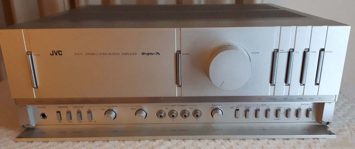
Physically, Model A-X9 looks more like a sleekly designed basic power amplifier than a full-featured integrated amp. That is because most of the less-often-used controls are concealed behind a hinged door panel which is normally closed, providing an uncluttered appearance.
The controls that remain visible with the hinged door snapped shut include a massive master volume control, calibrated in dB with reference to maximum setting, and six slim, vertically oriented, bar-type touch switches which handle power on/off, audio muting, tape monitor selection, and auxiliary, tuner or phono program-source selection. Secondary controls and features behind the closed door include the usual phone jack, two separate speaker selector buttons, a subsonic switch, a tone defeat switch, bass and treble tone controls, tape-2 in-and-out jacks (which parallel similar in-and-out jacks located on the rear panel), a balance control, and eight more small push buttons at the lower right of the panel. These switches include a Record Off switch which physically disconnects the record-out jacks from the rest of the circuitry to prevent possible loading effects when connected tape decks are turned off. A tape/record source switch follows (it reconnects the record-out jacks), then comes a dubbing switch, a tape-2 front-back switch (which selects the correct front or back terminals for tape deck connection), a tape 1/2 switch, a switch which selects moving-magnet or moving-coil circuitry for the phono inputs, and a phono selector switch which chooses phono 1 or phono 2 inputs. Since the MC/MM switch is separate from the phono 1/phono 2 switch, either set of inputs can accommodate either type of phono cartridge, MM or MC.
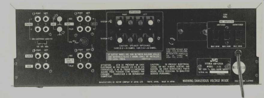
The rear panel of the A-X9 is equipped with the necessary phono 1 and phono 2 terminals, chassis ground terminals, a cartridge load selector switch (with settings for 47 kilohms, 100 kilohms and 100 ohms for MC cartridges), high-level in put jacks and two sets of tape-out, tape-in jacks. The two sets of speaker connection terminals at panel-center are clearly labeled as to channel and polarity. A line fuse holder and three convenience outlets (two switched, one unswitched) complete the rear panel layout.

Construction and Circuit Highlights
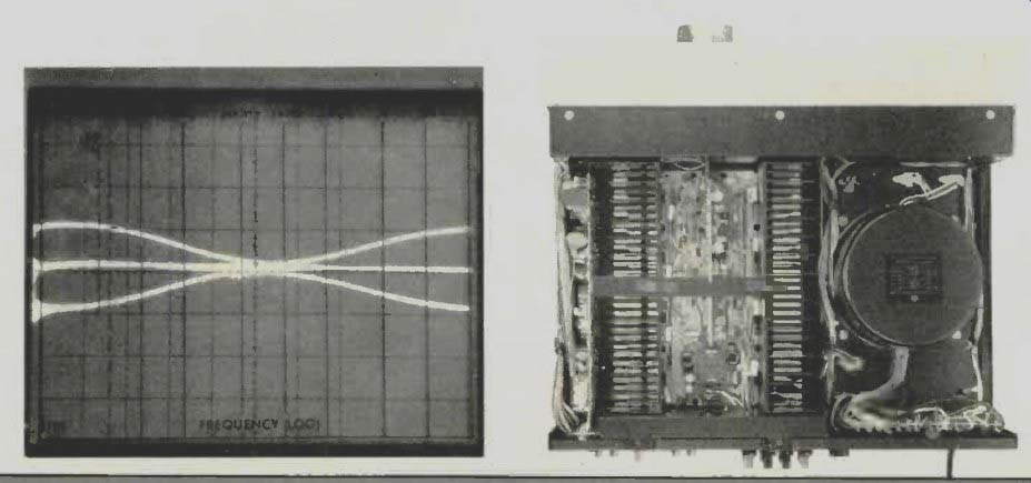
The high-capacity (380 VA) power transformer visible in the photo of the internal layout of the A-X9 is constructed with two sets of secondary windings. One of these is for the voltage amplifying stage, while a separate winding is used for output stage powering. For the early-stage supply, a constant-voltage circuit with a cascode amplifier is provided for low-impedance operation (less than 0.01 ohm) across a frequency range from 10 Hz to 100 kHz.
The most interesting circuit feature of the A-X9 is, of course, the Super A principle developed by JVC. Figure 1 shows a highly simplified circuit diagram of the Super A power stage. The portion within the dotted lines corresponds to the Super-A bias circuit, in which A1 and A2, on the one hand, and VB, and VB2 on the other, have identical functions and are arranged symmetrically in relation to the NPN and PNP side of the output stages.
The circuit operates as follows: A1 and A2 detect current variations of the power stage and apply input in the form of current output to VB, and VB2. VB1 and VB2 receive current output from A1 and A2 and perform current-to-voltage con version, thereby varying the bias voltage applied to the power stage. The current detection amplifiers at A1 and A2 have logarithmic input/output characteristics in order to properly control bias-voltage variation characteristics. E1 is a voltage-regulated circuit, the principal functions of which are to determine the amount of idle current at the power stage and to adjust that idle current for any wide temperature variations which might occur within the amplifier.
JVC has also come up with an innovative cascode amplifier circuit for use in earlier stages and in the driver stage of the A-X9 which, according to the company, reduces various forms of early-stage distortion that have previously not been dealt with. The basic circuit of this cascode amplifier is shown in simplified form in Fig. 2. This amplifier circuit is said to provide excellent linearity through a combination of the common-emitter and common-base circuits, since the forms of distortion created by each of these circuits individually are cancelled by each other. In this cascode circuit, input signal ID is first amplified R times by the common-emitter circuit Q1 which provides a large current gain. The signal is then applied to the emitter of the common-base circuit, Q2, where it is amplified oc times, thereby producing an output voltage across RL which is equal to:
Vo = oc Beta_RL IB.
According to JVC, this type of driver stage takes complete advantage of the properties of cascode operation and reduces the distortion figure in the voltage and driver stages of an amplifier by a complete order of magnitude compared with conventional amplifiers.
Performance Measurements
The power amplifier section of the A-X9 delivered 107 watts per channel at mid-frequencies for its ultra-low rated distortion of 0.005 percent. At 20 kHz, the amplifier was able to deliver just a bit more than its rated 100 watts for the same low distortion level. IM distortion was less than 0.002 per cent, lower than the residual IM distortion component present in our test signal source. We attempted to measure other forms of IM distortion, using our two-tone distortion measurement system, such as CCIF IM and IHF IM, but in all cases we were limited by the test signals and the measurement equipment, rather than by the amplifier's actual performance. There would be no point in presenting graphs of power output versus distortion or of distortion versus frequency at rated output, since such curves would, in reality, be nothing more than graphs of the distortion of our own test equipment! IHF dynamic headroom measured approximately 0.8 dB, while damping factor, at 50 Hz, was in excess of 150 for an 8-ohm load. Slew rate for the amplifier, measured from AUX in to speakers out was in excess of 50 volts per microsecond.
We made an attempt to measure TIM, per the square-wave/ sine-wave method which seems to be gaining general acceptance, but here, again, we could detect no evidence of TIM distortion contributed by the A-X9 amplifier itself. Frequency response was confirmed as extending from near-d.c. up to 220 kHz for the-3 dB roll-off points.
In measuring the phono preamp section, we found that RIAA equalization was accurate to better than 0.2 dB from 20 Hz to 20 kHz. Phono overload at 1 kHz using the MM input configuration was 380 mV, well above the 350 mV claimed by JVC, while for the MC inputs it measured 30 mV. Input sensitivities, translated to the new 1-watt output reference, worked out to be 0.25 mV for the MM inputs and 20 NV for the MC inputs. Signal-to-noise ratio was 84 dB for the moving-magnet phono inputs, a bit better than the 82 dB claimed, while for the MC inputs we measured 68 dB, some what poorer than the 75 dB claimed. S/N via the high-level inputs (referenced to 0.5-volt input and 1-watt output) measured 88 dB, as against 85 dB claimed, while residual hum and noise at minimum volume was an impressive 113 dB below rated output.
Tone control range is shown in the spectrum-analyzer sweep photo of Fig. 3. Note that JVC chose to limit the maxi mum range of the bass and treble controls to a moderate ±8 dB at the frequency extremes even though the A-X9 is a fairly powerful amplifier-a design approach with which we fully agree. Whether this moderate approach arises out of design philosophy on the part of JVC or out of some circuit necessity is really of no great concern to us, but we note that the A-X9 has no tone-control amplifier stage per se. Instead, the tone control circuit is incorporated as part of the negative feed back network of the power amplifier. One advantage of this approach, which does seem to be valid, is that all high-level signals, such as those from a tuner or tape deck, are directly fed to the power amp for true d.c. operation from input to output and with no intervening coupling capacitors.

Fig. 1--Simplified schematic of JVC Super A output stage. Fig. 2--Simplified
schematic of cascode voltage amp/driver stage used in Super A amplifiers.

Fig. 3--Range of tone control operation; vertical scale is 10 dB per division.
Use and Listening Tests
We found the JVC A-X9 amplifier to be a versatile unit that manages to incorporate just about every feature that a serious audiophile might deem to be important in an integrated amplifier. While it does lack secondary tone controls, such as a midrange or presence control, and variable turnover frequencies, it more than makes up for these minor deficiencies in its ultra-low distortion characteristics, whether measured statically or under dynamic conditions. Musical reproduction, using the A-X9 coupled to a pair of Phase Research RT speaker systems, was especially good when the amplifier was called upon to reproduce some of the more complex signal structures contained in many of our master tape recordings and in some of our new digitally mastered, high-dynamic-range discs. We cannot honestly say that sound quality was noticeably better specifically because of the Super A circuitry, but we certainly can have no objection to an amplifier which operates with the efficiency of a Class B unit, yet eliminates any possibility of switching distortion by always keeping its output transistors in a conducting mode. There has been a lot of controversy lately concerning the question of whether this design and other similar quasi-Class A amplifier design approaches deserve to be called Class A amplifiers. As far as I am concerned, that is purely a semantic question, and one that I'll leave to language authorities. My own feeling about the JVC A-X9 integrated amplifier is that it is a superbly designed piece of equipment that delivers good performance at any listening level, whether you call it Class A or Class Z.
-Leonard Feldman
(Audio magazine, Jul. 1980)
Also see: Link |
JVC Model R-S77 Stereophonic FM/AM Receiver (Equip. Profile, Jan. 1981)
JVC R-X500B Receiver (Equip. Profile, Dec. 1984)
JVC R-X80 Receiver (Nov. 1983)
JVC RX-9V A/V Receiver (Mar. 1987)
JVC S-300 FM Stereo/AM Receiver (Sept. 1976)
= = = =