MANUFACTURER'S SPECIFICATIONS:
FM Tuner Section:
IHF Usable Sensitivity: 10.97 dBf (1.9 µV).
50-dB Quieting Sensitivity: Mono, 16 dBf (3.5µV); stereo, 37.2 dBf (40µV).
THD, 1 kHz: Mono, 0.25; stereo, 0.4%. S/N: Mono, 70 dB; stereo, 60 dB.
Selectivity: 60 dB. Capture Ratio: 1.2 dB. Image Rejection: 70 dB.
AM Suppression: 50 dB. Stereo Separation: 1 kHz, 45 dB; 10 kHz, 30 dB.
AM Tuner Section:
Sensitivity: 300 kV/M, internal antenna; 30µV, external antenna. S/N: 55 dB.
Selectivity: 30 dB. Image Rejection: 45 dB.
I.F. Rejection: 50 dB.
Amplifier Section:
Power Output: 50 watts/channel continuous, 8 ohm loads, 20 Hz to 20 kHz, at no more than 0.31/4 THD. IM Distortion: 0.3% at rated output. Damping Factor: 50 at 8 ohms. Input Sensitivity: Phono, 2.5 mV; high level, 180 mV. S/N, "A" Weighted: Phono, 70 dB; AUX and Tape, 95 dB.
Phono Overload: 200 mV.
Frequency Response, Phono: RIAA ±0.5 dB. S.E.A.
(Graphic Equalizer) Center Frequencies: 40 Hz, 250 Hz, 1 kHz, 5 kHz, 15 kHz.
Range of Equalizer Controls: ±12 dB.
General Specifications:
Dimensions: 19-11/16 in. (50 cm) W by 6-5/16 in. (16 cm) H by 13-3/16 in. (33.5 cm) D.
Weight: 22.9 lbs. (10.39 kg).
Suggested Retail Price: $400.00.
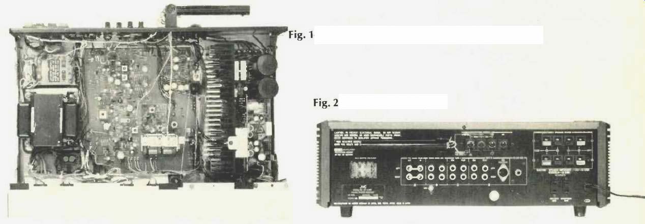
Fig. 1--Interior view, JVC S-300; Fig. 2--Back panel view.
For several years now, Japan Victor Company has been concentrating its advertising efforts on the promotion of the CD-4 four-channel disc concept. This emphasis has, per haps, distracted the public's attention from that company as a producer of excellently performing component equipment. Now, with the "big splash" promotion of quadraphonic equipment on the wane, the company has introduced a completely new line of integrated receivers which, outwardly at least, are as different from the conventional looking receiver as a quadradisc is from an old 78-rpm record.
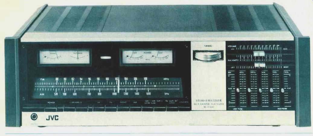
The front panel of the S-300 (a mid-priced unit of five similarly styled receivers) has no rotary knobs, with the exception of a single edge-mounted tuning control somewhat reminiscent of the thumb-wheel tuning knob used by Marantz on its tuners and receivers. This tuning control, positioned on a light colored section of the panel, divides the two main areas of the receiver's front. AM and FM frequency dials and pointer are sloped backwards to make them highly visible from above, and FM calibration points are linear and spaced at every half MHz. In addition to the usual tuning and signal-strength meters (at the left), are another pair of meters (to the right) which are accurately calibrated to read power output delivered to 8-ohm loads.
These meters, most often found on very expensive separate power amplifiers, can be used to monitor output power levels so that speaker power ratings are not exceeded or to balance stereo channel outputs.
Program source and all other functions are selected by means of 11 rectangular push buttons arranged in a neat single row below the dial area. Functions of these buttons, in addition to program source selection, include speaker se lection, tape monitor and dubbing selection (there are two tape monitor circuits), FM muting/mono selection, power on/off, and loudness circuit selection. A stereo indicator light is located between the two pairs of meters, while a headphone jack is located along the lower edge of the panel. Instead of the usual bass and treble controls, the S-300 receiver is equipped with a five-control graphic equalizer, which JVC calls S.E.A. (for Sound Effects Amplifier). Five slide controls divide the audio spectrum into five segments, and each control varies the output at a specified center frequency (listed in the manufacturer's specifications, above) by ±12 dB. To the best of our knowledge, JVC is the first company to incorporate a full graphic equalizer circuit into an all-in-one receiver, providing a much greater degree of tonal equalization than is possible with even the most elaborate bass and treble control arrangements. Each of the five S.E.A. levers moves in discrete click-stop or detented increments, permitting easy duplication of favorite settings.
Above these five controls are two horizontally moving slide controls which take care of master volume and balance adjustments.
The rear panel of the JVC S-300, pictured in Fig. 1, features spring-loaded speaker terminals for two sets of speakers.
The usual input and tape output jacks are provided, as is a multiple DIN socket for the Tape 2 connections. Preamp out/main amp in jumpers can be removed for separate ac cess to the preamp and main amplifier sections of the receiver, and an FM detector jack is also available for possible use with an FM four-channel adaptor in the future. The 75-ohm and 300-ohm antenna connections are in the form of screw terminals, one of which comes connected to a so called "indoor antenna wire" which must be removed be fore a normal antenna is connected. Switched and un-switched convenience a.c. outlets and the usual pivotable ferrite AM bar antenna complete the rear panel layout.
Circuitry and Internal Construction
While no schematic diagram is supplied with the owner's manual of the S-300, an examination of the internal construction of the receiver (See Fig. 2) and perusal of the company's descriptive literature yielded the following data. A single-unit four-resonator ceramic filter is use in the i.f. section together with a quadrature FM detector and a phase-lock-loop stereo decoder. AM circuitry is contained in a single multi-purpose IC. The FM front-end uses a three-section tuning capacitor and a dual gate MOS-FET r.f. amplifier stage. The phono preamp section includes a two-stage direct coupled PNP-NPN pair powered by a dual polarity supply. The amplifier section uses a differential input stage followed by a Class-A driver circuit. Output stages consist of a Darlington-connected, parallel push-pull, full complementary circuit. Several forms of protection circuitry are provided, including a speaker circuit relay, a d.c. voltage detector, and a speaker safety circuit which, according to the company, is covered by two granted U.S. patents. Dual-polarity output-stage voltage supplies are filtered by a pair of 10,000 uF filter capacitors.
FM Performance Measurements
IHF usable sensitivity of the S-300 measured 11.6 dBf (2.1 µV), while 50-dB quieting in mono was an exceptionally good 13.2 dBf (2.5 µV). Stereo sensitivity was limited by the switchover threshold to 25.2 dBf (10µV), and 50 dB of quieting in stereo was obtained with a signal input of 37.2 dBf (40 µV), exactly as claimed.
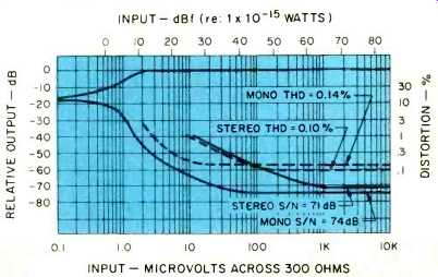
Fig. 3--FM quieting and distortion characteristics.
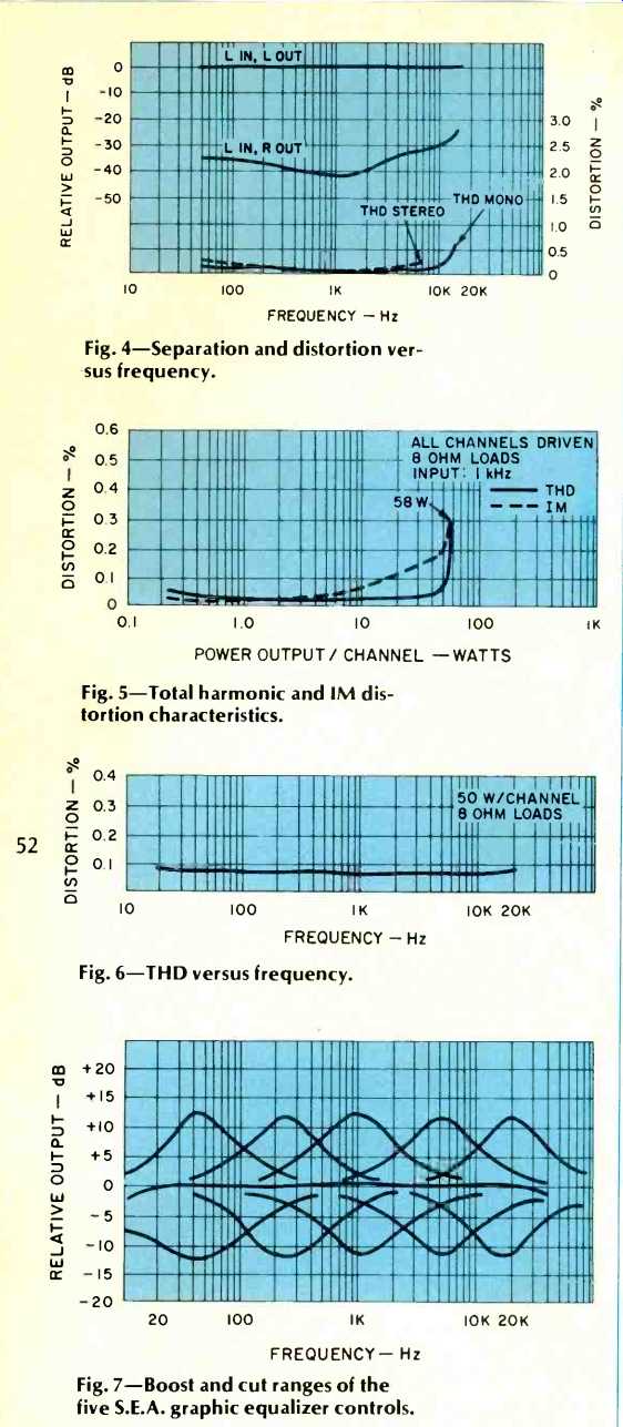
Fig. 4--Separation and distortion versus frequency.
Fig. 5--Total harmonic and IM distortion characteristics.
Fig. 6--THD versus frequency.
Fig. 7--Boost and cut ranges of the five S.E.A. graphic equalizer controls.
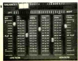
Fig. 8--These settings of the S.E.A. controls resulted in the response shown
in Fig. 9.
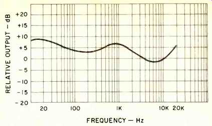
Fig. 9--Response curve obtained with S.E.A. control settings shown in Fig.
8.
In the area of S/N and THD the JVC S-300 did much better than claimed, with S/N readings in mono and stereo of 74 and 71 dB respectively and THD readings (at 1 kHz) of 0.14% in mono and, surprisingly, 0.1% in stereo. These results are shown graphically in Fig. 3. Selectivity (alternate channel) measured 63 dB, while image rejection was exactly 70 dB as claimed. Capture ratio at 45 dBf measured 1.3 dB. Spurious responses were down some 85 dB, and AM suppression measured 54 dB, again exceeding published claims.
Stereo separation and distortion versus audio frequencies are plotted in Fig. 4, and while separation at mid-frequencies fell short of the 45 dB claimed (it measured 42 dB, still a good figure), some 30 dB of separation was maintained all the way out to 10 kHz. There was little evidence of "beats" in the high frequency stereo THD measurements, and at 6 kHz in stereo THD was still a low 0.2%.
AM Tuner Section Measurements
External AM antenna sensitivity measured 27 µV, while signal-to-noise ratio in AM reached levels of 55 dB as claimed. I.f. and image rejection both measured 49 dB, and THD at 30% modulation was just under 1.0)/o, typical of AM circuit designs found in mid-priced integrated receivers.
Amplifier and Preamplifier Section Measurements
The amplifier section of the JVC S-300 is conservatively rated in that we were able to obtain 54 watts per channel at rated THD (0.3%) even at the frequency extremes of 10 kHz and 20 Hz. At mid-band frequencies, the amplifier section delivered 58 watts of continuous power per channel for its rated THD of 0.3%. At rated output (50 watts per channel), THD was only 0.065% while IM measured 0.18%, still well below the 0.3% rating. There was no evidence of notch or crossover distortion at lower output levels down to 0.25 watts (see Fig. 5), and any lower level readings were obscured by residual noise levels, as might be expected. Distortion versus frequency for the rated 50 watt per channel output level is plotted in Fig. 6 Phono input sensitivity measured close to the 2.5 mV stated and overload capability of this section was 220 milli volts, a bit better than the 200 mV claimed. S/N ratio in phono was measured both weighted and unweighted and were impressive with readings of 71 dB unweighted, 78 dB for the "A" weighted measurement. For the high level in puts, weighted S/N was 97 dB, while residual noise (with volume control fully counterclockwise) was 102 dB below rated output. All of these numbers would be considered excellent for a receiver at any price but are particularly outstanding in a medium-priced receiver such as the S-300.
S.E.A.GraphicEqualizerRange
Figure 7 is a graphic representation of successive sweeps on our spectrum analyzer in which each of the five frequency slide controls was moved to its boost and cut extreme positions. Action is precise and center frequency points are exactly where stated. The true flexibility of this five-control system can best be appreciated only when using the instrument in a music listening situation, but to indicate the flexibility of this graphic equalizer, we set the controls at arbitrary but reasonable settings, as shown in the close up photo of Fig. 8. The resulting response curve obtained with these settings is shown in the frequency response plot of Fig. 9.
Although JVC suggests that the end controls of the graphic equalizer may be used as high- and low-cut filters, a re examination of Fig. 7 shows that this is stretching their usefullness a bit, since the 40-Hz and 15-kHz cut action is such that response at those frequencies reaches a minimum (when controls are in their downward position) but rises again above and below those center frequencies. However, given the choice between a graphic equalizer such as this and conventional tone controls we would opt for the five control S.E.A. system every time. Obviously, it (like any graphic equalizer) can be over-used to upset response be yond belief, but if used for the purpose intended, the S.E.A. system on JVC's new receivers is by far the best tonal response altering system we have encountered on an integrated receiver.
Listening and Use Tests
Functionally, the "knobless" receiver takes a few moments of familiarization but the switching arrangement and slide controls give a professional feel to the set that is easy to appreciate and even prefer. Under strong signal conditions, both stereo and mono reception were excellent, and we detected none of that edginess or raspiness associated with less-than-perfect stereo multiplex circuits. JVC's engineers seem to have been able to extract a maximum amount of performance out of what is really quite an economical FM tuner circuit in the S-300 and their production departments have seen to it that alignment is well nigh perfect and calibration is right on target all across the dial.
We have to argue with the design philosophy that led JVC to couple the mono/stereo FM switch with muting on/off, because, when listening to stereo, it is impossible to defeat muting. Since the muting threshold on our sample was preset at about 24.5 dBf (9µV), the result is that weak-signal stereo signals will simply not come through unless that double-duty button is depressed, at which time the signals will be heard monophonically. Stereo switching occurs at 10 u V (25.4 dBf) so that at least there is fairly close compatibility between the two thresholds, but both of them might have been lowered a bit, in our opinion, especially since when stereo switching does occur, S/N is already better than 40 dB and THD is below 1.0''o in the stereo mode.
The rugged amplifier section and preamp control portion of the receiver cannot be faulted in any respect. The nominal 50-watt rating seemed every bit as conservative during listening tests as it did during our bench measurements, in that the receiver was able to drive low-efficiency acoustic suspension speaker systems to louder-than-life levels with a variety of record and tape program material which we use in our listening evaluations. The tape monitoring and dubbing facilities are sufficiently flexible to meet the need of serious recording buffs and record-out levels seemed fine in relationship to the line input requirements of our open-reel and cassette decks in the lab. JVC might want to consider providing equalized record output points as well as those which come ahead of the graphic equalizer in future designs, for it seems a pity to confine the use of that excellent S.E.A. graphic equalizer to playback only, but this is quite a small point.
In our opinion, JVC has managed to cram a great many circuit features and innovations into a medium-priced, good-looking receiver which offers exceptionally good value in its price range. Many of the features (plus some additional ones) are incorporated in the two higher-priced JVC receivers of this family (S-400 and S-600) and if you think you need more than 50 watts per channel and like the new JVC approach, these upper models might be worth looking at too.
------Leonard Feldman
(Audio magazine, Sept. 1976)
Also see:
JVC 4VR-5446 Four-Channel Receiver (Jan. 1974)
JVC RX-9V A/V Receiver (Mar. 1987)
JVC Model KD-85 Stereo Cassette Deck (Nov. 1978)
Harman-Kardon Model 900+ AM/FM Multichannel Receiver (May 1974)
= = = =