by RICHARD J. KAUFMAN
Years ago, one mark of a premium amplifier was the presence of filter switches labeled "Scratch" and "Rumble." These were supposed to eliminate the noise of rumble from the turntable and scratches on records, as well as hiss on tape and static on FM broadcasts.
Unfortunately, the circuits were usually simple affairs, with gentle roll-offs of 6 dB/octave. If they removed enough of the noise to be worth using, they removed too much of the program material to be desirable. Active filters make it possible to use a much steeper rate of roll-off so that the filter is effective without degrading the signal's frequency range unnecessarily.
Probably the most useful circuit that can be constructed by an amateur in the course of a weekend, the active filter also lends itself to use in crossover networks. Rather than splitting the highs and the lows with passive networks in the speaker system, active networks perform the task with low-level signals from the preamp. The high- and low-frequency signals are separately amplified and then fed to the woofer and tweeter. The many advantages of this approach-including lower distortion, greater effective power (due to splitting the spectrum between different amplifiers), and more accurate results (due to the absence of interaction between the filter and the speaker, which is inevitable with passive networks)--outweigh its greater cost.
The basic building blocks for second-order high- and low-pass active filters are shown in Fig. 1. The filter frequency (F) is determined by the following formula:
F = ½ π RC
The damping factor (d) determines the "flatness" of the filter's response. If it is too low, the filter will have poor Transient response. If it is too high, the filter's cutoff will be too gentle for most applications. A damping factor of 1.414 is usually optimum for a second order filter. Because some component values depend on the desired damping factor, it is best to first select those components (the capacitors in the lowpass and the resistors in the high-pass circuits) and then to select the other components according to the desired frequency. The resistors in the negative feedback loops (labeled "2R") are not critical, and they can be replaced with a short when maintaining minimum d.c. offset is not necessary.
A Modern Infrasonic Filter
While second-order filters are an improvement over the first-order scratch and rumble filters of days gone by, higher order filters offer better performance. Not many more parts are needed, so you might as well make the extra effort. Figure 2 shows a third-order infrasonic filter, the successor to the rumble filter. Such a filter will eliminate the very low-frequency record warp and tonearm-resonance signals.
These signals can rob your amp of power and can force the speaker voice-coil out of the magnet gap, reducing its distortion-free power-handling capability. Such problems can be so severe that the new IEC modification of the RIAA Standard for phono equalization calls for a roll-off of 12 to 18 dB below 20 Hz. Most phono sections do not provide this. The circuit in Fig. 2 effectively cuts infrasonic noise, and the improvement will be clearly audible. (Note that the damping factor for a third-order filter is 1. This is due to , the interaction with the extra first-order filter stage that has been added to the circuit.)
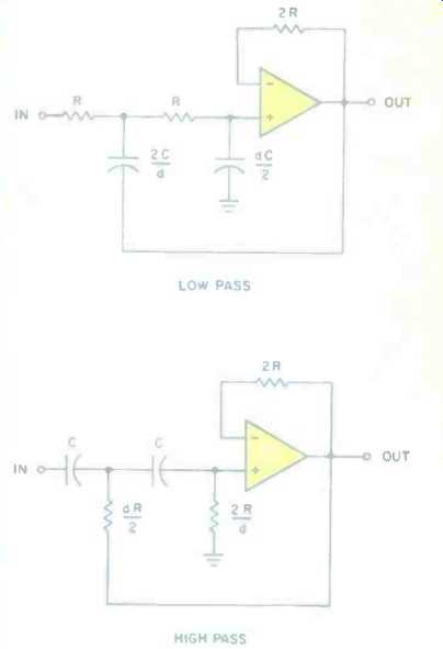
Fig 1--Basic, second-order low-and high-pass active filter circuits (see
text).
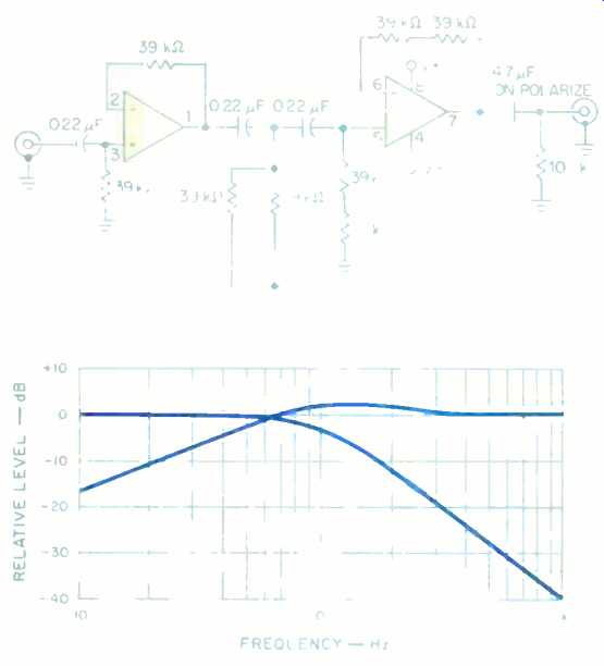
Fig. 2--A third order infrasonic filter with a roll-off of 18 dB/octave
below 20 Hz. The IC used is a dual op-amp, such as the TL072.
Fig. 3--Response of an asymmetrical crossover network.
An Asymmetrical Crossover Network
One case where a second-order filter is useful is in an asymmetrical filter.
This filter, used for speaker crossover networks, works by subtracting the output of a filter from the main signal.
You can start with either a high-pass or low-pass filter and derive the complementary response. Such a network's response is of constant magnitude and is linear in phase, resulting in perfect transient response. Unfortunately, the complementary response (the one derived by subtraction) rolls off at a rate of 6 dB/octave, regardless of the order of the filter used, and has a bump near the cutoff frequency that grows progressively larger as the order of the filter is increased (Fig. 3). For this reason, only the second-order asymmetrical filter is really practical. To make things even worse, the phase difference between the high and low signals is such that the drivers must be very close together, relative to the wavelength at the crossover frequency, or the advantages of linear phase thus will be lost.
Note the differing slopes of the low and high-pass sections, and the response bump near the crossover frequency.
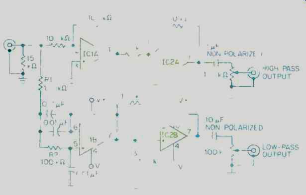
Fig. 4--An asymmetrical subwoofer crossover. Its crossover frequency, 112
Hz with the component values shown, can easily be altered (see text).
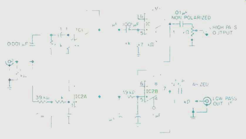
Fig. 5--A fourth-order Linkwitz-Riley crossover, configured for a crossover
frequency of 2.8 kHz.
For very low frequencies, close speaker spacing is easy to achieve, and I have found that such crossovers give very good results for subwoofers whose crossover point is in the range from 100 to 200 Hz. Figure 4 shows a crossover that has worked very well for me in this application. The crossover frequency for the component values shown is 112 Hz. By changing the values of the two 100-kilohm resistors (R1 and R2) that feed into pin 5 of IC1B, it is possible to change the crossover frequency; by using 68-kilohm resistors, for example, the crossover point will become 165 Hz.
I find it works better to use the sharper filter (12 dB/octave) to keep the high frequencies out of the subwoofer and to use the milder filter (6 dB/octave) for the high-pass section, at least with the set of drivers I have tried. A low-pass filter should be used for the bass, and the complementary response will be the high-pass response. Since the high-pass response will then roll off at 6 dB/octave, the main speakers' response should extend an octave below the crossover frequency. In other words, if your crossover is set at 165 Hz, then your main speakers should have a low-end response that extends down to at least 83 Hz.
The Linkwitz-Riley Crossover
The problem with third-order crossover networks is that, although they provide very good pressure response, the phase difference between the signals results in very uneven response distribution in the vertical plane. This is also a problem with the asymmetrical filter discussed above. A fourth-order filter will have both outputs in phase at the crossover frequency, making driver placement less critical and. yielding much better vertical dispersion.
The classic fourth-order Butterworth filter, while having a flat power response, does not give a flat pressure (voltage-summing) response. In a reverberant field such as a home listening room, flat pressure response is required. It can be obtained with a type of filter popularized by Siegfried H. Linkwitz. Unlike the classic Butterworth crossover, in which the filters' responses are down by 3 dB at the crossover point, the Linkwitz filters' responses are down by 6 dB at the crossover frequency. The high- and low-pass responses are in phase at crossover, resulting in a wide vertical dispersion.
Transient response of these filters is quite good. Due to the phase requirements, only even-order Linkwitz filters exist.
Figure 5 shows a fourth-order Linkwitz-Riley crossover for a frequency of 2.8 kHz. The crossover frequency can be changed by altering the value of the resistors and capacitors, using the following formula:
F = ½ π√2 RC
The 78-kilohm resistors can be made up from two 39-kilohm resistors in series. The filters' roll-off rate is 24 dB/ octave, which means the upper frequency speakers can be crossed in much lower (and the woofer crossed in much higher) than would normally be the case. For example, this crossover can be used with many tweeters that would have to be crossed in at 5 kHz or higher (even with a second-order crossover) because of their power handling difficulties at lower frequencies. Problems due to beaming by the woofer at higher frequencies are also eliminated by the sharp roll-off. Until digital filters become readily available, this will probably remain the filter of choice for high-performance active crossovers.
Construction Tips
Op-amps should be FET-input devices, such as the LF353, TL082, or TL072. The latter device is preferred, though the others will give adequate performance. Pinouts are the same on all three chips and therefore are interchangeable.
Capacitors used for active filters should be plastic-film or silver-mica types. Metallized polyester is acceptable, as is Mylar. Polypropylene and polystyrene capacitors are even better, but it is arguable whether the difference is audible. The output capacitors should be nonpolarized: Plastic film types, though not readily available in the specified sizes, are preferable; electrolytic caps are acceptable.
Again, it is debatable whether the difference can be heard. If you are worried about a possible degradation in sound, electrolytic caps can be bypassed with film or silver-mica capacitors of smaller value. The tolerances for capacitors and resistors should be 5% or better, though 10% will not seriously degrade performance.
Any power supply delivering between ±6 and ± 18 V will work. The power requirement per op-amp is less than 50 milliamps.
=================
Build A High-Blend Control
Stereo reception of FM is all too often marred by hiss and birdies, bleeps and howls that disappear when the tuner is switched to mono mode. These noises, caused by multipath reflections, affect the multiplexed (L-R) signal, while the hardier mono component of the signal remains noise-free and undistorted. Although switching to mono does result in listenable reception, doing so amounts to throwing away the proverbial baby with the bath water: The noise is primarily above 5 kHz, and the portion of the audio spectrum that allows stereo to give an illusion of directionality lies mostly between 500 Hz and 2 kHz.
What is needed is a way to blend only the high-frequency sounds to mono, leaving the midrange unaffected, to provide an adequate degree of stereo separation. Why such a feature s not found on more mid-priced tuners and receivers is a mystery, the parts or a simple high-blend control would cost the manufacturer less than a dollar. The parts will cost you only slightly more.
The schematic of a simple high blend control is shown in Fig. 1. The circuit is placed between the tuner and the preamplifier, or in the tape-monitor loop when using a receiver. The capacitor should not be ceramic; Mylar, metallized polyester, and silver-mica, however, are all acceptable types. The value shown, 0.001 µF, begins blending the right and left channels above 3 kHz when used with a preamp having 50 kilohms input impedance. If your unit varies from this standard value or interference is especially bad in your location, you may want to use a different capacitor value. A larger capacitor lowers the frequency at which blending occurs. A higher impedance will require a smaller capacitor, and vice versa. I suggest that you experiment to find what value capacitor will provide optimum blend while maintaining adequate separation with your equipment.
The switch is necessary to disable the blend control. The potentiometer, which is optional, controls the maximum amount of blend that will occur.
Thus, separation can be maintained at a higher value when noise levels are not as severe. Finally, you should mount all the parts inside a metal project box to prevent hum and noise pickup.
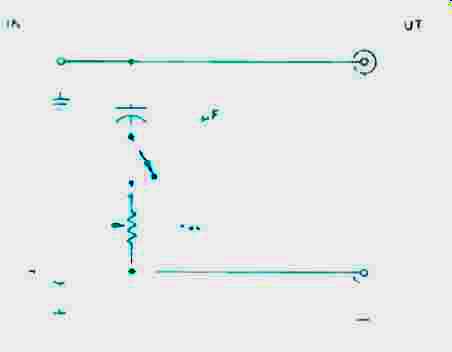
Fig. 1--A simple high-blend control. The potentiometer is optional (see
text).
For some people, this high-blend control will make it possible to listen to their favorite stations in stereo. Even if the stations you normally listen to wouldn't benefit by the addition of a blend control, more distant--and perhaps more interesting-stations will become listenable.
(adapted from Audio magazine, Jul. 1988)
Also see: EQ & NR: Striking A Balance (Aug. 1988)
Cable and the Amp / Speaker Interface (Aug. 1989)
The Audio Interview: E. Alan Silver--The Connoisseurs’ Selection (July 1988)
= = = =