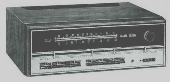
MANUFACTURER'S SPECIFICATIONS:
FM TUNER SECTION: IHF Sensitivity: 1.8µV (1.5 µV typical). S/N: >60 dB; Capture Radio: 1.5 dB; THD (Mono) 0.5% or less; Selectivity (Alternate Channel): >70 dB; Image Rejection: 90 dB; I.f. Rejection: 90 dB; Spurious Response: >90 dB; Stereo Separation: 45 dB typical at 1000 Hz.
AM TUNER SECTION: Sensitivity: 30 µV at 600 kHz, 20 µV at 1400 kHz, with external antenna; Antenna: Built-in rod type, adjustable; THD: 2%; Hum and Noise: -35 db.
AMPLIFIER SECTION: Power Output: 100 watts total IHF music power, 8-ohm load; RMS Power Output/Channel: 35 watts, 8-ohm load; THD: 0.25% at rated output; Power Bandwidth: 5 Hz to 30 kHz. Hum and Noise (IHF): High Level Input: -75 dB; Phono: -65 dB; IM Distortion:0.2%; Input Sensitivity: Phono: 2.2 mV; Tape Monitor and Aux: 180 mV; Frequency Response: Aux: (1-watt level) 7 Hz to 60 kHz ±1 dB; Damping Factor: 50.
GENERAL: Power Requirements: 110-125 or 210-250 V, 50/60 Hz, 55 watts idling, 240 watts at full output; Dimensions: 16 3/4" wide, 5 1/8" high, 14 1/2" deep; Cabinet: AE-19 pecan finished, or custom mounted.
Weight: 26 1/2 lbs.
Price: $285.00; AE-19
Cabinet: $19.95.
The Heathkit AR-29 is a worthy companion to the famous AR-15-somewhat easier to build, somewhat lower in power, somewhat less expensive-but nevertheless a superb receiver in its own right.
After a thorough study of the instructions, we built it, got it to working perfectly, and then enjoyed its performance for some time before making the usual measurements required to complete a report on the unit.
In external appearance, the AR-29 seems simpler than the AR-15, inasmuch as it has only one "knob," and that is the tuning control. Volume, bass and treble tone, and balance are all handled by slide controls which move horizontally just under the back-lighted front panel.
Function and source selection are controlled by fourteen push buttons, and the only other component on the front panel is the stereo headphone jack. On the rear are the barrier-type output connector strip, the center-speaker switch, two convenience outlets-one switched and the other unswitched-and the line fuse.
Openings in the bottom plate provide for adjusting the signal levels from all sources so that outputs from whatever input are of equal level. The input phono jacks are all mounted on the flat surface of the chassis top, with a portion of the rear cover shielding them from the internal circuitry. These jacks, incidentally, are permanently mounted to the input preamplifier circuit board, which also accommodates the level-adjusting pots, all the electronic components, and at its front end the pushbutton assembly, which is the source selector.
The construction of the receiver is of a new design which employs eight printed-circuit boards, resulting in relatively few components being mounted on the chassis itself. These circuit boards are fitted with receptacles which mate with six-pin Molex plug assemblies which are mounted in several places on the chassis in their nylon snap-in bodies. After they are installed, the wiring is made to the plugs with cable harnesses, resulting in a simplified wiring procedure.
The individual circuit boards are completed separately so the builder has a number of small projects to finish, rather than one large and cumbersome assembly. Thus he has the feeling that something has been accomplished with the completion of each of the boards. Actually, there is a lot of work in putting these boards together, and the overall construction time for the receiver is likely to be around 35 hours-very similar to that for the AR-15, although much simpler for the constructor. After all the circuit boards are completed, they are installed one at a time in the chassis and tested in accordance with the instructions. No external test equipment is required, since there is a test panel with a pair of switches mounted inside the chassis, and the signal meter is used as a voltmeter to test supply voltages at various points through the chassis, and also as an ohmmeter for other measurements that ensure correct wiring. On the whole, the construction and final testing is a short course in electronics, well done as is usual with Heath instructions, and effective enough that it is not necessary to give a final alignment with instruments to get the receiver operating in accordance with its specifications.
Circuit Description
The circuit, which employs 65 transistors, 42 diodes, and four integrated circuits, differs considerably from the AR 15. The output amplifiers employ positive and negative supply voltages, eliminating the need for output coupling capacitors and thus improving the response in the very-low-frequency region. Starting with the r.f. section, the FM front end is embodied in a tuning unit which has two r.f. amplifier stages, a mixer, and an oscillator. The input accommodates either 75- or 300-ohm antenna lead-ins, and feeds the primary of a transformer whose secondary is tuned by the main tuning capacitor, and which feeds the gate of an FET. Its output is coupled to the second r.f. stage-a bipolar transistor-which is in turn coupled to the base of the mixer transistor, which is also coupled to the oscillator. The a.f.c. voltage is fed from the detector to a voltage-variable-capacitance diode which alters the oscillator frequency to hold the stations in tune.
The AM tuner employs two FETs as r.f. amplifier and mixer, and a third as oscillator. The AM antenna is a ferrite rod, which is encased in a plastic housing and is adjustable in position over a wide range. The i.f. stages follow the mixer, then the diode detector, and another FET that serves as the AM meter amplifier. A 10-kHz filter eliminates interchannel squeal, and an emitter follower feeds the remaining circuitry.
The FM i.f. amplifier employs an integrated circuit, followed by a nine-pole passive filter-which must be fairly complicated since its replacement cost is listed at $18.00-followed by two more ICs, the last one feeding the ratio-detector transformer, followed by the two-stage direct-coupled audio amplifier, and by the FET which provides the a.f.c. voltage back to the oscillator. There is also an a.g.c. amplifier, a signal-meter amplifier, a signal-differential amplifier, and a muting-voltage amplifier. The output of the FM/AM i.f. amplifier chassis is then fed to the multiplex circuit board where it is fed to an elaborate IC which performs practically all of the demodulating functions for the stereo-signals. Its two stereo outputs are fed to separate two-stage amplifiers, filtered, and thence to the control preamplifier circuit board. Two switches are provided on the MX board for alignment of the 19- and 38-kHz circuits separately.
The input preamplifier circuit board provides the necessary gain and equalization for the phono inputs, with low-noise transistors being used in the first stage.
Supply voltages are sufficiently high that, along with the circuit design, the overload at the phono input is a comfortable 155 mV, which should take care of any cartridge likely to be used with this receiver.
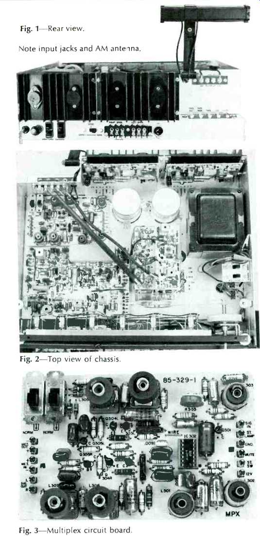
Fig. 1--Rear view. Note input jacks and AM antenna.
Fig. 2--Top view of chassis.
Fig. 3--Multiplex circuit board.
The control preamplifier is the section which provides the tone controls, balance control, and the volume control. A single unit, two-transistor Darlington device is used in each channel to provide sufficient gain for the tone controls, and when the TONE button is depressed, the tone-control circuitry is bypassed, providing flat response throughout the entire range.
The output amplifiers are constructed on printed-circuit boards which are integral with the heat sinks when completed, The input is fed to a pair of transistors operating as a PNP differential amplifier.
The input is fed to one base, while the feedback is applied to the other one. A pre-driver stage furnishes amplification to the PNP driver on one side of the circuit, with the NPN driver supplies the signal to the other side. A complementary pair of transistors is used as a dissipation limiter, with a total of seven diodes maintain control against overdrive of the two 2N3055 output transistors.
The power-supply section provides regulated voltages of 12 and 50 to the circuits requiring regulation, and a separate bridge rectifier furnishes the positive and negative 35-volt supplies to the output stages. Dual primaries on the power transformer permit connection for operation on either 117 or 220 volts (nominal) when required.
Performance
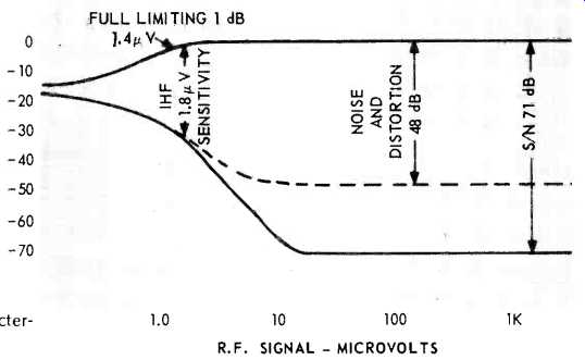
Fig. 4--FM characteristics
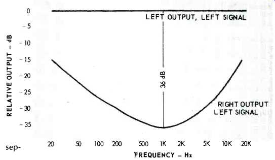
Fig. 5--Showing separation
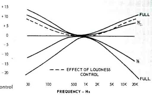
Fig. 6--Tone control curves
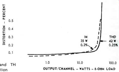
Fig. 7--IM and TH distortion
Figure 4 depicts the FM characteristics of the AR-29, which show the excellent sensitivity, as well as the fine quieting of the receiver. Channel separation is shown in Fig. 5. All of these curves put the AR-29 in the category of most of the high-quality receivers on the market-that is to say there are few which can outperform it. Figure 6 shows the effect of the tone controls at full and half positions. Boost at 20 Hz is shown to be about 15 dB, and cut about 22 dB. On the high-frequency end, the boost and cut are more moderate, +10 and -20 showing as the response at 20 kHz. The dashed line on the same figure shows the effect of the loudness button when depressed, raising the response at 20 Hz by 10 dB, and at 20 kHz by 8 dB. Distortion figures are plotted in Fig. 7, with a measured distortion of 0.15 per cent as typical over most of the audio range, even though the specifications rate the receiver at a distortion of 0.25 percent.
As a check on the effectiveness of the signal meter, we measured the signal required to move the pointer to the five points on the meter scale. A signal of 36µV would cause a deflection to the first division, 60 µV to the second, 85 µV to the third, and 125 µV to the fourth division. An input of 160 µV would deflect the signal meter fully to the fifth position on the scale. With the MUTE button depressed, a signal of 6 µV would silence the set, but even then, the S/N was some 56 dB. Once silenced, a signal of 21 µV was required to disable the mute circuit.
We noted a power output of 36 watts per channel at a distortion of 0.15 per cent, with both channels driven, and at the rated distortion of 0.25 per cent, we measured an output of 42 watts per channel.
Power bandwidth also exceeded specifications, extending from 7 Hz to 43 kHz at the half-power point. Frequency response at the 1-watt level was from 7 Hz to 62 kHz, ±1 dB, and from 4 Hz to 110 kHz ±3 dB, also exceeding specifications. Full limiting occurred at an input signal of 1.4 µV, while IHF sensitivity measured 1.8 µV.
Listening Test
After such an impressive set of measurements, we could only hope that listening tests would bear out what we had measured, as indeed they did. We first found that we could pull in 26 stations with only our finger on one of the FM antenna terminals, which was impressive in itself. After we connected the antenna, we brought in 43 stations, with 32 of them in stereo. These figures should not be compared with others reported, since our location does not provide the enormous number of stations available to the New York area, but to date we have never pulled in over 41 stations heretofore with any receiver, and not all of them were listenable. One effect we noticed as a result of the a.f.c. circuitry--as we tuned up to a station and it snapped in, it would then remain in tune for a short distance of the dial pointer, shutting out a station adjacent to the strong one. However, if we approached the desired weak station from the other side, it could be tuned in successfully.
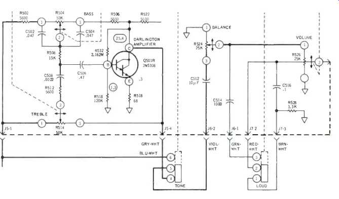
Fig. 8--Showing Darlington tone control circuit.
Even the AM reception was excellent--after we corrected an error in connecting the a.g.c. diode which was originally in reverse. This created a funny effect, since the weak stations were very weak, while the strong ones were awfully strong. But the ease of removing the i.f. circuit board made changing the diode a very simple operation, and then performance was excellent, even with the built-in rod antenna. We did not connect an external AM antenna, since we had no intention of trying for a long-distance reception record--the built-in antenna furnished all the stations we wanted in the AM band.
With reasonably efficient loudspeakers, the AR-29 should suffice for even the most hardened and critical listener. Its 35 watts per channel is more than adequate for most loudspeaker systems, and far more than could be used in an apartment of the usual construction.
The ease of construction and the completeness of the instructions make the assembly a pleasant procedure, and the completed receiver is a handsome piece of equipment. Its performance should satisfy the most serious audiophiles thoroughly.
-C. G. McP.
(adapted from Audio magazine, Aug. 1970)
Also see:
Heathkit AA-1800 Stereo Power Amp (Equip. Profile, Sept. 1982)
Heath AJ-2520 Tuner (Mar. 1990)
Heathkit Model AA-1640 Stereo Amplifier (Nov. 1976)
= = = =