MANUFACTURER'S SPECIFICATIONS
Rated Power Output: 200 watts per channel into 8 ohms, both channels driven, with less than 0.1 percent total harmonic distortion from 20 to 20,000 Hz.
Intermodulation Distortion: Under 0.1% at full power.
Frequency Response: -1 dB from 7 Hz to 50 kHz and -3 dB from 5 Hz to 50 kHz.
Meter Range: 0.2 to 200 W into 8 ohms; - 30 to +3 dB.
Rated Output Level: 1.5 V. Weight: 58 lbs. (26.3 kg).
Price: $439.95; AAA-1640-1 meter, $69.95; kit purchased with meter, $489.95.
---------------
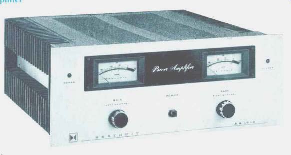
The AA-1640 is Heathkit's entry into the amplifier horsepower race. It is physically larger than most other amplifiers in the 150-300 watt/channel class and weighs in at 58 pounds. The kit is available with or without the AAA-1640-1 output meter accessory. The kit reviewed was built by one of the staff of Audio and was equipped with the output meter accessory.
The amplifier is built around an internal U-shaped chassis upon which are mounted the power transformer, two 7500 µF/100 V filter capacitors, main supply rectifier bridge, and a socket for the power supply and speaker protection circuit PC board. Connecting to the rear of this internal chassis is the rear panel' of the unit and to the front is a tranverse sub panel that is about 60 percent of the amplifier's height. Two L-shaped side pieces connect the front sub-panel to the front panel of the unit. Two enormous heat sinks form the outer side pieces of the amp and connect the rear panel to the rear of the aforementioned L-shaped side pieces. Each heat sink has an associated main power amplifier circuit board that connects along one edge to the power transistor socket pins on the heat sink and to two multi-pin male connectors mounted to the top edge of the internal chassis. A U-shaped piece of aluminum on each main amp board serves to conduct heat away from the pre-driver transistors and to mechanically tie down the connector edge of these boards by bolting to the upper sides of the internal chassis.
A speaker output relay is mounted to the front sub-panel under the left main amp circuit board. The input buffer amplifier is mounted near the bottom of the unit on the front side of the front sub-panel. Another relay for preventing excess in-rush a.c. line current upon turn-on is mounted on the inside of the rear panel and is covered over by a protective piece of aluminum. Circuitry for the peak-reading meters is in the form of two PC boards mounted to the back of the meters with the meter terminal bolts.
On the front panel are the two peak-power meters, power On and over-temp LED indicators, two input gain controls, and a push-button power switch. Mounted on the rear panel are the a.c. line cord, a.c. line fuse, two speaker fuses, speaker connector socket, and two signal-input female phono connectors. The speaker sockets accept two polarized plugs each with two screw terminals, a quick connection arrangement.
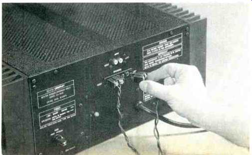
Fig. 1-Back panel.
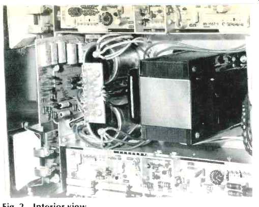
Fig. 2-Interior view.
Circuit Description
As is shown in the block diagram, the input signal, after passing through the input level control, is applied to the input buffer or unity gain amplifier. The purpose of this amplifier is to present a relatively high signal-input impedance (50 K-Ohms with level controls clockwise) and a low output impedance to drive the main amplifier. Circuitry for this amplifier consists of a NPN-PNP compound pair with 100 percent feedback from second-stage collector to first-stage emitter.
The input stage of the main power amplifier circuit is a PNP differential amplifier with a transistor current source. The collector of the input diff amp is direct coupled to the base of a NPN transistor which, in conjunction with an associated PNP, form a compound predriver stage. Such a connection is like the input buffer except that the output is taken at the emitter of the PNP transistor, rather than the collector. This results in a linearized (by local feedback) effective common-emitter amplifier and is a logical step, as this stage has to produce the full amplifier output-voltage swing.
A constant current source from the plus 91 V supply is connected through the output-stage bias diode network to the output of the compound lower predriver stage. Quiescent current in the composite predriver is about 20 mA. The output stage of the AA-1640 is a quasi-complementary one similar to that used in a number of other high power amplifiers and uses eight RCA 1605 Pi-Nu output transistors.
Dynamic output limiting is in the form of a VI limiter which shunts away base drive to the output stage if current and/or voltage in the output stage is considered beyond safe bounds. Overall negative feedback is taken from the output back to the inverting input of the input diff amp through two paths. A speaker protection fuse is placed between the output stage and the output RLC buffer network and is included in the main feedback loop (12 k) in order to eliminate the series resistance of the fuse. The secondary loop is a higher (68 k) path from the output stage back to the inverting input to keep the amplifier d.c. centered when the fuse opens. Located on the plug-in power-supply PC board is the speaker protection circuit. This circuit, by controlling a relay in series with the output terminals, functions as a turn-on time delay and a speaker protector by opening up the relay it the d.c. output voltage of either channel goes more than a few volts, plus or minus, from ground.
Two thermal cutouts, one on each channel heat sink, are wired in series with the speaker relay coil and, if either channel heats up excessively, will open the relay, thus removing the load from the amplifier. Also on the plug-in power-supply board are six rectifier diodes, two Zener diodes, and associated resistors and filter capacitors to provide plus 12 V for the speaker relay, regulated plus and minus 15 V for the speaker protection circuitry, input buffer amps, and meter circuits. An additional plus 35 V is developed for the LED indicator diodes. The main high voltage supply for the power amp proper is plus and minus 91 V at idle across two 7500 µF, 100 V filter capacitors.
A line-operated relay shorts out a 5-Ohm resistor in series with the power transformer primary as fast as it can pull in upon power turn-on. This helps to reduce the high a.c. inrush current that would otherwise occur.
The peak-reading meter circuit consists of a full-wave, two-diode, break point linear-to-log converter, a differential amplifier, a diode peak detector, and an emitter-follower buffer driven by the storage capacitor. The circuit is arranged so that negative feedback is applied around the peak detector and buffer back to the inverting input of the diff amp so that the buffered peak-held voltage matches that coming from the linear-to-log converter. This insures that the circuit will respond to short narrow input pulses.
The decay time is longer than 0.5 seconds. When a peak comes along, the circuit quickly (less than 50 µS) captures the peak and holds it long enough for the meter movement to come up to the correct indication. Actually, the held voltage is decaying while the meter is coming up to deflection but this amounts to a relatively small error.
Kit Builder's Notes
This is a big kit, with a lot of parts, so a large bench or desk area that can be monopolized for several weeks should be the unpacking site. I found empty egg cartons handy for nuts, washers, and bolts, as well as Rs and Cs, while other parts, such as relays, fuse holders, etc., hibernated in the paper bags they were packed in.
While Heath does supply a plastic nut driver and a small wrench, you'll also need a soldering iron, screwdriver, wire cutters, and a long-nose pliers. I strongly suggest here that a good pencil-type iron be purchased, if you don't already have one, since the cost is low when one thinks about the time involved in going back to look for cold solders. It will also get the work done faster.
Total time spent on the project was about 23 hours, which was spread over a 7-week period with a couple of weeks out in the middle. The work seemed to go more quickly if I spent a couple of hours at the bench each day; usually I worked in the early morning in an attempt to escape a combination of a hot soldering iron and 90° weather. While this is easily the largest kit I have ever worked on, I was not intimidated principally, I believe, because of Heath's usual fine manual and a growing sense of accomplishment as I completed each section. One starts out building a small VOM, which is later used to check various construction stages and parts. The parts density of the various boards is moderately high, but this did not interfere with construction as Heath has laid the steps out the easy (read sneaky) way. Mechanical construction was simple.
Troubles? Relatively minor when one considers the complexity of the kit. One open and one shorted transistor in the right channel required a trip to the Heath parts depot for replacement during the late stages of construction.
Strain on the associated parts in this channel may be what later resulted in the other channel having better measurements. Quite clearly, however, the unit was operating properly after the cover was finally buttoned on.
The amplifier sounded extremely good to me during a short listening test performed with a Shure V-15 III on a Technics SL-1350, Phase Linear 4000 preamp, Marantz 20B tuner, Sony 277-4 tape deck, and Duntech DL-15 speakers.
Bass was strong with good definition, and the midrange seemed clean and warm, though the highs seemed very slightly compressed in dynamic range. This is one of the more powerful amps I have ever auditioned, and one should normally expect to run out of speaker before this amp quits.
In its overload characteristics, the 1640 seemed quite forgiving and smooth, without the "crunch-clunk" which sometimes occurs. For me this is an amp I can live with easily, one of the best around. Besides, I had fun building it.
-E.P.
Listening Tests
Listening was done with Dahlquist DQ-10s and Magnepan MG-IIs, both on loan from the manufacturers for amplifier review purposes. Phono pickups used were Supex SD-900, Fidelity Research FR-1 MK 2, and an EMT XSD-15, all moving-coil units. A newly acquired M&K-modified Rabco SL-8 arm was used for this testing. Preamps used included a Levinson JC-2 GAS Theadra, and the reviewer's own reference moving-coil tube preamp. The sound of this amplifier when compared to some of the better bipolar amps previously reviewed is noticeably softer in nature. When the program source is dean, the AA-1640 seems to very slightly dull some of the transients and remove a bit of the spaciousness and air about the instruments. On the other hand, when the source signal is dirty and edgy, which unfortunately is far too often the case, the amp seems to make the overall sound less distorted and more musical sounding. These effects are certainly not gross but are discernable to a highly critical listener. When driven hard and into clipping with difficult low impedance loads, the AA-1640 sounded clean with graceful, non-offensive overload characteristics. If this reviewer had to pick between the AA-1640 and one of the many solid-state amps that are on the edgy side of neutral, the choice would be unhesitatingly for the sound of the Heath.
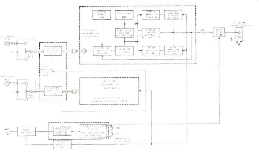
Fig. 3--Block diagram.
Measurements
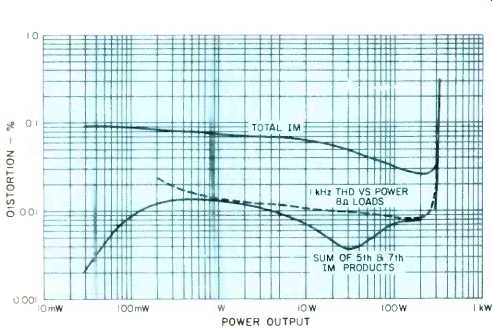
Fig. 4--IM and harmonic distortion vs. power output.
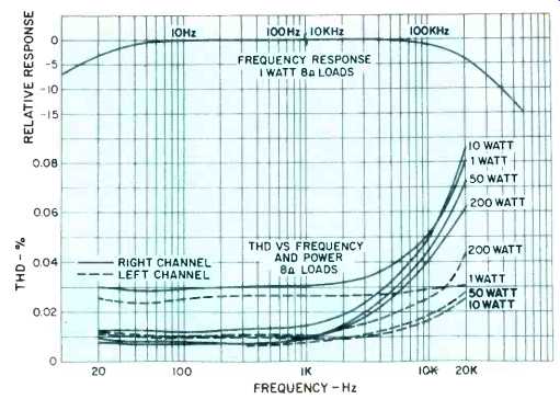
Fig. 5--Top curve, 1-watt frequency response into 8-Ohm load (note
break in curve at 100 Hz/10 kHz). Bottom curves, THD vs. frequency and
power into 8-Ohm loads.
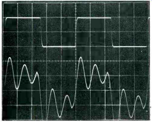
Fig. 6--Top trace, 10-kHz square wave into 8-Ohm load; bottom trace, 10-kHz
square wave into 2-µF load. (Scales for both traces: 5V/cm, 20 µS/cm.)
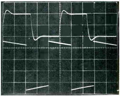
Fig. 7--Top trace, 10-kHz square wave into load composed of 2µF in
series with 2 Ohms; scales 5V/cm, 20 µS/cm. Bottom trace, 50-Hz square
wave into 8-Ohm load at 200 watts; scales, 40 V/cm, 5 mS/cm.
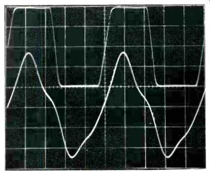
Fig. 8--20-kHz square wave into 8-Ohm load; bottom trace, 20-kHz sine
wave into 1-uF load. (Scales for both traces: 20V/cm, 10 µS/cm.)
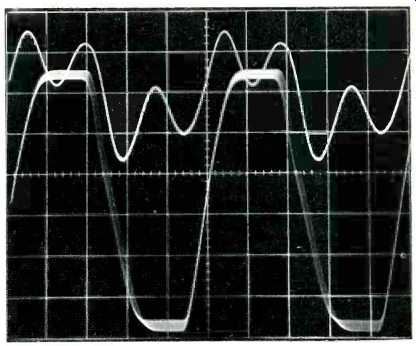
Fig. 9--Top trace, 20-kHz square wave into 1-µF load; scales, 10V/cm, 10
µS/cm. Bottom trace, 20-kHz sine wave into 8-Ohm load at 2-dB overdrive;
scales, 20 V/cm, 10 µS/cm.
The AA-1640 was run at one-third of rated power or 66.7 watts per channel into 8-Ohm loads for one hour with 'a 1-kHz sine-wave test signal. The heat sinks got hot after one hour but not excessively so.
Voltage gain was measured and found to be 29X (29.2 dB) and 27.5X (28.8 dB) for the left and right channels respectively. IM distortion and 1-kHz THD are shown as a function of power in Fig. 4. It was found that this amplifier had quite different distortion characteristics in the two channels. The right channel appeared to be under-biased compared to the left and generated more distortion at low levels and high frequencies. The right channel figures are shown in Fig. 4.
Figure 5 has THD plotted vs. frequency and power for both channels, along with the 1-watt frequency response. The differences between the channels are most readily apparent in the nature of the rise in high frequency distortion. It is not known whether other AA-1640s have a more closely matched behavior between channels. However, note that all these measurements are within spec. An attempt was made to raise the idling current in the right channel by adding a small resistor in series with the five bias diodes. Distortion could be lowered but the increase in idling power required was too much.
Figure 6 is for a 10-kHz square wave at 10V p-p output with 8 Ohm and 2 µF loads. Ringing is fairly pronounced as in other amplifiers, but is considerably improved (as would be other amps) with the addition of 2 Ohms in series with the 2 µF which would be a good deal more representative of the situation with an actual capacitive transducer. This is shown in the top trace of Fig. 7. The bottom trace is a 200 watt, 50-Hz square wave into 8-Ohm loads. Low frequency tilt is noticeably more than some of the better a.c. coupled amps reviewed. Figure 7 shows a 80 V p-p 20-kHz square wave into 8 Ohm loads. The asymmetry of the leading and trailing edges suggests the current source predriver load can't pull the output stage plus as fast as the compound pre driver can pull it minus. Corresponding slew rates are about 11.4 V/µS for minus to plus and 20 V/µ S for plus to minus transitions. Recovery from slewing is smooth and well damped. The bottom trace of Fig. 7 is for a 20-kHz sine wave into a 1-uF load. Distortion under these conditions is low up to about 150 VA and then begins to distort as shown. It appears that VI limiting prevents the amp from delivering 200 VA at 20 kHz. An attempt to drive a 20 kHz square wave into 1uF is shown in the top trace of Fig. 9. Severe asymmetry begins to occur above the level shown. The bottom trace is for a 2 dB increase in input level beyond the onset of visual clipping at the output for a 20-kHz sine wave into 8-Ohm loads.
The blurring of the trace is due to 120-Hz power supply ripple modulation of the output signal. Sticking per se is relatively absent in this waveform. The behavior with high frequency reactive loading suggests that the AA-1640 might possibly be in audible distress with some of the more inefficient electrostatic transducer loads when pushed to very high power at high frequencies. As has been mentioned under the listening tests, the amp is fine at high powers with conventional speaker loading and indeed may be perfectly OK with electrostatic speakers.
Damping factor was measured as a function of frequency and was found to be higher for the left channel although such differences between channels are not unusual. Both channels came to the same values above 5 kHz. Low frequency values for the left channel were about 213 and with about 160 for the right. The right channel decreased smoothly to 145 at 1 kHz dropping to 46 at 7 kHz and 16 at 20 kHz.
Output noise as a function of measurement bandwidth and input gain control position appears in Table 1. The left channel was producing some 60 Hz hum and high frequency 60 Hz gated bursts with the gain control at about half rotation. It is felt that this was not amplifier instability but something else in the chassis that was picked up by the input circuit when the source impedance to the input buffer amp was highest.
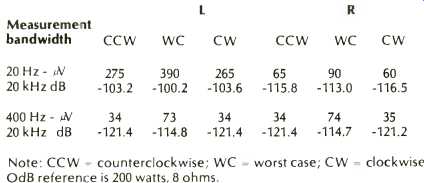
Table 1--Output noise vs. bandwidth and input gain rotation.
The meters were checked for steady-state reading accuracy. The figures are rather impressive, i.e. 462 watts/channel into 4 ohms, 320 watts/channel into 8 ohms, and 189 watts/channel into 16 ohms, all with a 1-kHz sine wave until visual onset of clipping. It wasn't possible to check for reading accuracy for short transient signals due to the lack of a tone burst generator when testing the amplifier. It is believed that the meter circuit would perform well for transient signals due to the inherent nature of the circuit design. The AA1640 met its published specs with the two exceptions of 1-watt 20-kHz THD in the right channel and noise (60-Hz hum) in the left channel with the input level control other than fully clockwise or counterclockwise.
Measurements and the fact that the right channel wasn't as good as the left side, the amplifier sounded quite good to this reviewer. If the novice kit builder has doubts about whether he has constructed his AA-1640 correctly, despite its having passed the tests Heath has in the construction manual, the builder can have the unit checked over by one of Heath's competent technicians to make certain everything is in order.
-Bascom H. King
(adapted from Audio magazine, Nov. 1976)
Also see:
Heathkit AA-1800 Stereo Power Amp (Equip. Profile, Sept. 1982)
Heath AJ-2520 Tuner (Mar. 1990)
Heathkit Model AR-29 AM-FM Stereo Receiver (Aug. 1970)
= = = =