By Jan deVries and Michael Lampton
few n the theory of low frequency loudspeaker performance. [1,2,3,4] Furthermore, the growing popularity of electrostatic tweeters has brought a number of excellent commercial high frequency reproducers to the market, available at reasonable prices. Taken together, these facts lead to the conclusion that the hobbyist who wants to put together a high performance loudspeaker system can do so in a straightforward way, and have confidence in achieving the performance goals he sets.
One of us has a good size living room and decided some good performance loudspeaker enclosures would increase the general living enjoyment and comfort of the room.
The project loudspeaker systems were fun to plan and build, and they work so well, that we want to share the ideas and details with other AUDIO readers. Bear in mind that there is a great deal of flexibility in the design: the shape of the cabinet, the mounting configuration of woofer, tweeter, and duct, the choices of woofer and tweeter. Because of this flexibility, we have tried to avoid loading this article down with too many details or precise dimensions. Nonetheless there is enough information for the home constructor to come up with a pretty close carbon copy, if he wishes.
The simplest and sometimes cheapest type of loudspeaker system is a "one-way" system, where one or more similar loudspeakers cover the entire range of frequencies to be reproduced.
Such systems face a severe compromise, however, when it comes to choosing a loudspeaker size: For smooth response and wide dispersion above a few kilohertz, the loudspeaker should be no more than an inch or so in diameter, while for low distortion below 100 Hz it should be at least six to eight inches.

One way around this situation is to arrange a large number of medium-size speakers on a curved baffle surface, to improve the total high frequency radiation pattern; the low frequency response is still often deficient, however. Another technique is to employ a loudspeaker whose effective cone area decreases with increasing frequency; these loudspeakers have mechanical crossover networks which give many of the benefits of two-way systems.
Two-way loudspeaker systems use separate woofer and tweeter units for the reproduction of the bass and treble notes. They have the advantage of permitting each unit to be optimized for its part of the spectrum with the result that broader total frequency response and less distortion can be achieved.
This article describes a reasonably simple two-way system which realizes these advantages.
The Electrostatic Tweeter--A push-pull electrostatic loudspeaker element consists of a thin conductive membrane suspended between two wire grids. In operation, the membrane is kept charged to a potential of 1000 volts or so, and the signal to be reproduced is applied between the grids. Thus the signal takes the form of an alternating electric field between the grids, and the membrane experiences an electrostatic force proportional to the audio signal. If the membrane is sufficiently thin and light, this force is directly applied to the surrounding air, and the radiated sound pressure directly tracks the applied audio voltage.
The frequency response limitations of an electrostatic loudspeaker are as follows. At the high frequency end, the response will start to fall off when the inertial forces required to accelerate the diaphragm become comparable to the radiation resistance of the air; thus response to (say) 30 kHz requires membranes thinner than about 0.1 milligram per square centimeter. The fact that strong metallized plastic films of this thickness (thinness?) are readily available is what enables reliable electrostatic tweeter elements to be made cheaply. At the low frequency end, the response is limited by the necessary tension in the film suspension and by the radiation cutoff due to the element's finite size: The response will start to drop off when the element's diameter is less than about a quarter wavelength. Thus, a three-inch by three-inch square unit will not be useful below about 1 kHz..
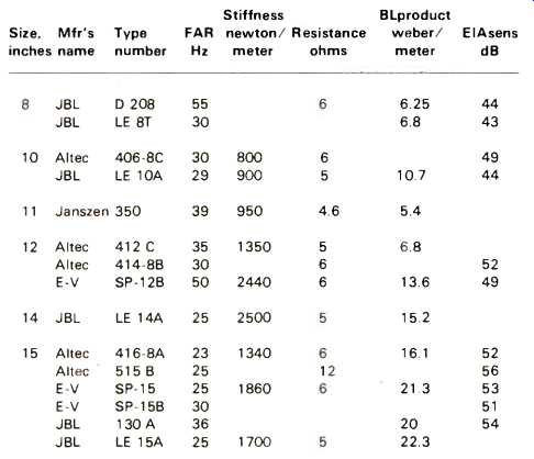
TABLE 1. Important Properties of a Few Loudspeakers
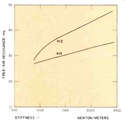
Fig. 1--Woofer free-air resonance vs. stiffness.
Electrostatic tweeters have several advantages over the usual moving-coil tweeters. Foremost is, of course, their extended high frequency response, which goes about one octave higher than dynamic units. More significant is the fact that the electrostatic's response curves are inherently exceedingly smooth; the peaks and valleys, which are produced by the acoustical impedance mismatch between a heavy cone or dome and the surrounding air, are absent.
There are two important limitations of electrostatic loudspeakers, however. First, because they radiate well only at wavelengths smaller than their size, they produce appreciable beaming of the radiated sound. Consequently, at least two elements should be used in a corner-located system, angled 45° to 60° from each other; even more elements are needed in a wall-mounted or bookshelf system. Second, electrostatics have limited power handling capacity owing to the required strong electric fields and close grid spacing. Although perfectly adequate for living room sound levels, they are not suited for auditorium or outdoor sound reinforcement applications.
Rather than build our own tweeters, we purchased the Janszen Model 65 electrostatic loudspeaker unit, which includes two four-inch square elements and the required high voltage power supply, as well as a high quality step-up transformer needed to match the elements to an eight-ohm amplifier output.
Although the Janszen unit contains its own high pass filter with a 700 Hz cutoff point, we chose a somewhat higher crossover frequency and so found it acceptable to leave the manufacturer's high-pass filter in place.
The Woofer--The low-frequency radiator for this project system was designed using the technique described by Lampton and Chase (AUDIO December, 19735). The enclosure type is a fiber-filled bass-reflex system, which has the greatest practical figure of merit of all common enclosure types and is not particularly difficult to build. In this system, our design objectives were to achieve an asymptotic efficiency of 2 per cent, while maintaining a 3 dB cutoff frequency below 30 Hz. From the Design Curve #1 of Lampton and Chase, such a system will require an enclosure volume of 7 cubic feet if air-filled, or 5 cubic feet if glass-wool fiber-filled. This particular level of efficiency means that, when driven from a 50-watt amplifier just reaching its clipping level, the system will yield 1 acoustic watt. In a typical living room, this corresponds to about 110 dB SPL (!) which is surely enough for any foreseeable application.
By the way, this efficiency is about two to five times as great as is provided by the usual type of bookshelf loudspeaker systems, and the 30 Hz cutoff constitutes about a one-octave improvement over such systems. Although there are few steady tones found in this part of the spectrum in musical passages, there is substantial transient power in this bottom octave associated with percussion.
In order to come up with a woofer capable of satisfying these ambitious design objectives, we applied the method of Lampton and Chase twice. First, as in their design example #1, we plotted up the allowed maximum woofer free-air resonance versus suspension stiffness for 12-in. woofers giving a 30 Hz cutoff in a ten-cubic-foot enclosure (equivalently, a seven cubic-foot fiberglass-filled enclosure). This enclosure volume is larger than is absolutely necessary, but the extra volume allowance will give us a nice large working range of woofer parameters. This design constraint is shown as the upper curve in Fig. 1. Second, as in design example#3 of Lampton and Chase, we plotted up the allowed woofer parameters which can give at least a two per cent efficiency in a ten-cubic-foot enclosure. This design requirement then leads to the lower curve in Fig. 1. Any 12-in. loudspeaker whose free air resonance and suspension stiffness lie between the two curves in this figure will then satisfy both sets of requirements. Note that if we had not started out the calculation with any more volume than necessary, we would have ended up with only a skinny line in Fig. 1, on which the chance of finding some commercial woofer would have been quite small.
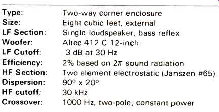
TABLE 2--Properties of the Project System
Are there any woofers which will do the job? After exchanging correspondence with several manufacturers, perusing a variety of specification sheets, and borrowing a few loudspeakers from friends for measurement, we made a table showing the more important parameters of a number of popular types; it is reproduced below as Table 1. Among the 12-in. speakers, the Altec 412 and 414 lie within the OK zone of Fig. 1 and so could be used in the present project. The Electro-Voice SP-12B lies just above this zone, and could be used if its FAR were lowered a few Hertz by putting adhesive tape on the cone, or if the 30 Hz cutoff were slightly relaxed.
The particular woofer we chose for the project system was the Altec 412. Although it is nominally a wide-range speaker, and could have been used alone without an outboard tweeter, we regard the addition of the electrostatic tweeter as an improvement.
Having chosen an enclosure size and a specific woofer, we are all set to finish the design by calculating the duct details and then establishing the proper damping. From Fig. 7 of Lampton & Chase we see that we shall need a duct air mass ratio of 1.2; since the woofer has a mass of 28 grams, we find a needed duct air mass of 34 grams. This is provided by a duct having a cross section of 6 by 12 inches, and whose length is 9 3/4 inches, from the duct formula for 12-in. woofers:
duct length (inches) = .0082 m A - A
where the desired mass, m, is expressed in grams, and the duct cross section area A is expressed in square inches.
The damping is established from the required speaker Q, given for example in Fig. 9 of Lampton & Chase: optimum performance would be obtained with a Q = 0.45. The chosen speaker has an inherent Q of about 0.5, meaning that it is slightly less damped than it should be for this application. The discrepancy is not serious enough to warrant fiddling with negative output impedance amplifiers. Had we wished to raise the speaker's natural Q value, a one- or two-ohm external series resistor would have accomplished the job.
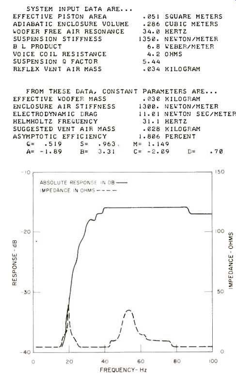
Fig. 2--Computer generated amplitude response and impedance plots.
We ran a computer evaluation of the final woofer/enclosure design. The computed response plot is shown in Fig. 2. The plot verifies that the response should indeed be quite flat down to about 40 Hz, and be down 3 decibels at 30 Hz. A computed impedance curve is also shown.
The Crossover--In a two-way loudspeaker system, it is necessary to electrically divide up the audio spectrum into the frequency ranges the woofer and tweeter are capable of handling. This is accomplished with low- and high-pass filters. An important decision is to choose between a high-level or a low-level crossover network. A high-level network is designed to handle the output of the power amplifier, and is connected between the amplifier and the two speakers; a low-level network is connected between the preamplifier and two power amplifiers (one for the woofer, one for the tweeter). Low-level crossover systems were once called "electronic" crossovers, but that term is more properly reserved for distinguishing either from mechanical crossovers. The advantage of the high-level crossover is that only one power amplifier channel is needed to drive the entire loudspeaker system. It has the disadvantage that rather cumbersome LRC components are needed to handle the required power with low distortion. Experimenters prefer low-level crossover systems, largely due to the ease with which the crossover frequency, cutoff slopes, and relative gains of the LF and HF channels may be varied. Although we chose the low level method, we feel that either technique can give good results.
The choice of a particular crossover frequency is a compromise governed by these two limitations: the low frequency power limitation of the tweeter, and the high frequency response irregularities of the woofer. The lower the crossover point, the more total power must be handled by the tweeter. Since tweeters (especially electrostatics) are capable of only small linear excursions, too low a crossover point can lead to severe distortion. On the other hand, a high crossover point delivers substantial midrange power to the woofer, and this midrange power may not reproduce and disperse smoothly. For the present system, we found a crossover frequency of 1000 Hz to be satisfactory, based on manufacturers' recommendations and on a number of listening tests.
In the vicinity of the crossover point, the woofer and tweeter reproduce a comparable sound level. As a result, the sound you hear is a combination of the woofer and tweeter response. The goal of the crossover design is to drive the speakers in such a manner as to have the total system response as flat as possible. Incidentally, the filters should also have steep cutoff slopes in order to keep the crossover region as narrow as possible. It is especially important to keep the LF power out of the tweeter circuit, to minimize distortion.
The designer would have an easy time of it if he were given the task of crossing over a two-way system for use on axis in an anechoic chamber. This is because on axis, the woofer-to-listener and tweeter-to-listener distances can be equal. Consequently the combination of the woofer and tweeter responses referred to above is exactly the sum of their separate sound pressures. So, on axis and with no reflected sound, you would obtain a flat overall frequency response curve by making sure that the total woofer plus tweeter voltage is constant with respect to frequency.
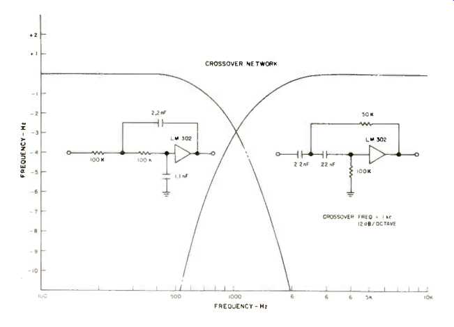
Fig. 3--Crossover network.
Out in the real world the situation is rather more complicated. Off axis, the woofer and tweeter sound pressures combine in a manner which depends on the difference in the phase shift along their paths to the listener. Reflections off walls and ceilings further complicate the picture, and it is quite difficult to make a system which takes all these individual phase shifts into account. The total sound power integrated over all angles can, however, very simply be made flat: We simply require a crossover network whose power gain to the woofer plus power gain to the tweeter, is constant with respect to frequency. This approach is justified by the fact that under most listening conditions, reflected sound constitutes the greater part of the total (direct plus reflected) sound perceived. Reflected sound contains a large number of component paths, and among these the phase shifts are almost completely random; randomly phased signals add up as their total power, rather than as the sum of their individual sound pressures. It should be noted that there are a few applications where constant voltage and not constant power is appropriate. For example, in coaxial two-way loudspeakers the woofer and tweeter are within a quarter wavelength of each other and their sound pressures add directly.
There have been a good many crossover circuits described in the literature. Here, we'll give the details of a simple high-pass, low-pass filter which is easy to make and can be easily adjusted in frequency. It is known to engineers as a "two-pole Butterworth" filter, and has a power gain given by

...where f is the frequency of the signal and fo is the crossover frequency. It is clear from formulas that the sum of the two power gains is 1, i.e. it is independent of f. Each section has a cutoff slope of 12 dB/octave. The filters can be built using only voltage followers (FETs, IC op amp followers) as active elements. A schematic is given in Fig. 3, along with the response curves of the HF and LF sections.
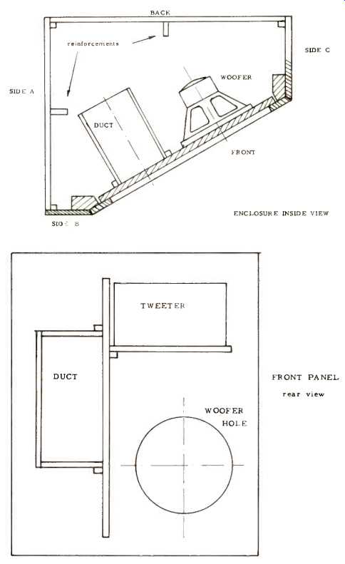
Fig. 4--Drawings of cross-section and front panel.
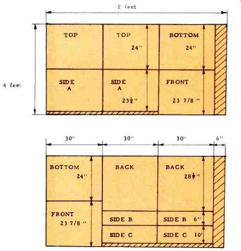
Fig. 5--Layouts for cutting major cabinet sections from two 4x8-ft. pressed
wood sheets. Other materials needed are 10 ft. of 2x4 in. for corners of
front panel, 50 ft. of 1x1 in. for corners, 10 ft. of 1x3 in. to give added
stiffness to enclosure, 3x4 ft. plywood to construct the duct and shelf
on front panel, fiberglass for inside lining and stuffing, wood glue, No.
8 flathead wood screws, and veneer to finish.
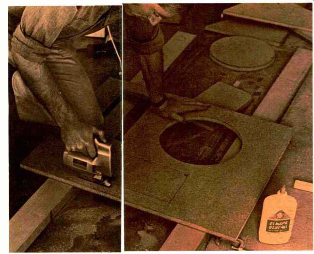
Construction--With our components selected, we drew up plans which provide the required 7 cubic foot internal enclosure volume while making good use of the corner locations selected. The left hand and right hand enclosures are not identical, but are mirror images; due to the shape of the living room a 30° front-panel angle was preferable to the more customary 45°. Each front panel was drawn up with the tweeter directly above the woofer, with a great deal of internal bracing being provided by the shelves and ducts. Figure 4 shows a view of the assembly, and the photographs detail the relationship of the parts. The front panel and all shelves, etc. are made of rigid 34-inch particle board, which is denser and less resonant than laminated plywood. All internal panels are reinforced with securely fastened 1x2 and 2x4 lumber for added stiffness, removed from the enclosure for ease in installing the speakers or changing the grille cloth.
1. All panels for two enclosures can be cut from two pieces of 4x8 foot particle board, as shown in Fig. 5. If you have no table saw, a saber saw can be used for these long straight cuts provided that you clamp a straight 1-in. x 4-in. strip parallel to the desired cut to act as a saw guide. Lumber retailers charge about $5 for the 20 minutes of labor needed to cut up the panels.
Since the finished enclosures will be covered with veneer, you have considerable tolerance in the straightness of the cuts, and no 45° bevel joints are necessary.
2. Measure in 3/4 inch from the inside edges of the bottoms and tops, and install 1-in. x 1-in. square glue block strips. For a removable front panel, make sure that there is no interference at the left and right sides with these blocks.
3. Secure the top and bottom to the sides and one rear panel. You'll have a much neater job if you put the screws in from the inside on all panels except the one removable rear panel. These joints should be glued as well as screwed down tight.
4. Install the tweeter shelf and duct on the front panel. Use plenty of glue here since this panel must be rigid. Paint the front panel surfaces flat black. The loudspeakers can be installed before or after the grille cloth is stapled around the front of the panel. The staples will be covered by the front frame when the panel is installed. The wiring can be installed at this point; it's convenient to mount a barrier-type terminal block on the non removable rear panel for the connections to the woofer and tweeter.
5. Cut up 4-inch thick fiberglass insulating wool into four inch cubes. Loosen up the material as much as possible; remove any foil which may be attached to the fiberglass. Staple some very loose cheesecloth over the rear of the woofer, and fill the entire enclosure with the fiberglass cubes. Avoid packing the duct with them; more cheesecloth will probably be necessary here.
6. The rear panel can now be put into place with plenty of screws, and the whole system checked out. An audio oscillator is very helpful here. With a powerful amplifier, drive the woofer with a level of several watts at frequencies between 10 Hz and 1 kHz. Listen and feel carefully for any sign of panel resonance, which would reveal itself as a vibration or buzzing.
7. The best finishing job for the enclosure is done with commercially available wood veneer and contact cement. Make sure that the surfaces to be covered are flat, especially at the joints.
Cut the veneer slightly oversize and coat the surface of the veneer with fast drying contact cement. When the cement dries, place a sheet of newspaper over the surface and center the veneer on the newspaper. Slowly withdraw the paper, allowing the veneer to contact the surface progressively. (With contact cement, you get no second chance!) With the veneer completely bonded, the edges can be trimmed using a razor blade or a sharp hobby knife. Several coats of shellac or acrylic resin, such as "Deft," will give the veneer sufficient hardness to stand up under everyday wear and tear.
Start Your Own Design. The starting point for a custom design is to decide on the best speaker locations in your listening room. The locations should face as much of the listening area as possible, and be chosen with good stereo or quadraphonic panorama in mind. Corner locations are usually best. Try to avoid placement where much reflected sound can get to the listening area; hard flat surfaces are the most troublesome. One or two dominant reflections will give rise to severe frequency response irregularities throughout the midrange (as you can verify with an oscillator) while numerous distant reflections are not at all harmful. Good listening rooms are remarkably dead; hi-fi showrooms have thick carpets and heavy drapes for more than one reason!
Since physical laws tell us that the larger the enclosure, the better the bass will sound, bear in mind that you will want to base your design on the maximum available enclosure size.
Some thought should be given as to how you'll camouflage the monster once it's built. For instance, select an exterior veneer which blends with your other furnishings. Avoid grille cloth patterns which are too colorful and attention grabbing. An enclosure looks bulky if its frontal area exceeds about six square feet. A good way to obtain the needed volume is to choose enclosure locations where a good deal of depth is available, as is often the case in corners.
If you already own some loudspeakers and are considering building enclosures for them, you'll want to put them through the series of measurements described by Lampton & Chase to find out what their properties really are. If the enclosure is to give maximally flat response down to the woofer's free air resonance, you'll need an enclosure volume of:
V = A^2/s cubic feet
where the woofer piston area is A square inches, and s is the suspension stiffness in newtons per meter. Big, compliant woofers require very large cabinets to get down to their FARs.
An even larger cabinet permits a response to below the FAR. If you plan to select a new woofer for your system, contact as many manufacturers as you can. Many offer plans and even blueprints for building enclosures suited to their speakers.
These plans are real bargains and disclose a number of useful assembly and mounting tricks, and can be helpful even if you don't use their specific designs.
Tweeter selection is more difficult than woofer selections, largely because their problems show up at the high end of the audio spectrum where lumped-constant thinking (e.g. Table 1) is inapplicable. A tweeter is perhaps best selected by ear. The things to listen for are smooth response (absence of harshness) and wide dispersion. Tweeters are of three kinds: direct radiator cone or dome types, driver/horn combinations, and electrostatic. Direct radiators are the cheapest and are reasonably efficient but too often show beaming and response irregularities above about 5 kHz. A small diameter is important if beaming is to be avoided. Horn-type tweeters are more costly but have much lower distortion and greater efficiency as a result of the impedance transformer action of the horn. They are well suited to high-power applications and generally have the lowest distortion of the three types. Due to their appreciable moving mass they are usually limited to frequencies below about 10 kHz. The low-frequency limit of a horn tweeter is set by the length and flare rate of the horn. For a one-foot length, the crossover frequency will have to be above 1 kHz. Electrostatic tweeters are best with regard to achieving a wide smooth response, but they are a bit fragile and will distort badly if overdriven.
REFERENCES
I. "Loudspeakers in Vented Boxes." by A. Neville Thiele, Proc. I.R.E. Australia vol. 22, p. 487, 1961, and reprinted in Journ. A.E.S. vol. 19,#5 p. 382 and #6 p. 471, 1971.
2. "The Theory of Maximally Flat Loudspeaker Systems," by Susan Lea and Michael Lampton, IEEE Trans. Audio and Electroacoustics AU-20,#3, p. 200, August, 1972.
3. "The Theory of Bounded-Ripple Loudspeaker Systems" by M. Lampton, IEEE Trans. Audio and Electroacoustics AU-20, 45, December, 1972.
4. "Efficiency of Direct Radiator Loudspeaker Systems" by Richard Small, Jour. A.E.S. vol. 19, #10, November, 1971, p. 862.
5. "Fundamentals of Loudspeaker Design" by M. Lampton & L. M. Chase. Audio, December 1973, p. 40.
6. "Vented-Box Loudspeaker Systems" by Richard Small, Jour. A.E.S. vol. 21, #5, 6. 7; June, July/August, September, 1973; p. 363. 438, 549.
(adapted from Audio magazine, Aug. 1974)
Also see:
Electrostatic Speakers: Theory and Practice -- Part 1 (Mar. 1989)
= = = =