Manufacturer's Specifications:
ML-10A Preamplifier
RIAA Equalization Accuracy: ± 0 30 dB.
Gain: Phono, 42, 53, or 63 dB, switch-selectable; line, 22 dB.
Distortion: Phono, 0.014% THD and 0.005% IM at 6 V output, 20 Hz to 20 kHz, 63-dB gain; line, 0.004% THD and 0.004% IM at 6 V output, 20 Hz to 20 kHz.
S/N Ratio: Phono, - 72 dB, 20 Hz to 80 kHz, re: 1 mV input at 1 kHz, 63-dB gain; line, 95 dB, unweighted, re: 2 V.
Volume-Control Tracking: ± 0.50 dB in typical usage range.
Line Input Impedance: 15 kilohms.
Recommended Load: Main out puts, 5 kilohms or more; record outputs, 10 kilohms or more.
Dimensions: 2 1/4 in. H x 19 in. W x 10 1/8 in. D (5.7 cm x 48.3 cm x 25.7 cm).
Weight: 8 lbs. (3.6 kg).
Price: $2960.
ML-9 Amplifier
Power Output: 100 watts per channel, 8-ohm loads, 20 Hz to 20 kHz; 200 watts per channel, 4-ohm loads.
Distortion: 0.2% THD for 100 watts output, 8 ohms; 0.4% THD for 200 watts output, 4 ohms.
Damping Factor: Switchable, 300, 200, or 100 at 50 Hz, re: 1 watt at 8 ohms.
Input Impedance: 50 kilohms.
Dimensions: 8 3/4 in. H x 19 in. W x 13 3/8 in. D (22.2 cm x 48.3 cm x 34 cm).
Weight: 56 lbs. (25.5 kg).
Price: $3,050.
Company Address: c/o Madrigal, P.O. Box 781, Middletown, Conn. 06457.
============
Editor's Note:
The particular units reviewed here were produced by the "old" firm, prior to legal difficulties early this year. However, new samples have been diligently checked by the reviewer, who tells me that beach tests show them to be quite "substantially like the units tested last fall." Bascom further says, "I have also listened to them and find they sound like the original units. I think that we can run the original review with a few words in postscript to that effect." Our company contact tells us that insofar as they are concerned, the only change is in the ownership of the company, and that they have not changed the units inside or out.
-E.P.
============

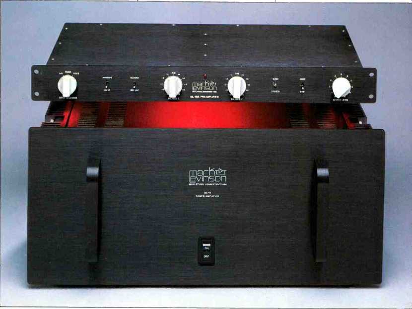
The ML-10A preamplifier and ML-9 amplifier stand about midway in the hierarchy of Mark Levinson Audio Systems (MLAS) components. Both are typical MLAS designs, save that the ML-10A breaks with the company's tradition of separate power supplies for preamps, as its power supply has been successfully incorporated into its chassis. Like all MLAS preamps, the ML-10A is a no-frills design, with a minimum of amplifier blocks or switches in the signal path.
Both the amp and preamp are rack width, but are not really designed for rack mounting. The preamp's mounting holes are not spaced to match standard racks; the amp has no mounting holes at all, because the makers recommend placing it near the speakers rather than racking it with the preamp. The ML-10A has a front-panel height of 2 1/4 inches and a depth of 10 1/8 inches, a very convenient size for a preamp.
The preamp's front-panel controls are sparse, in keeping with the MLAS design philosophy. From left to right, they include a three-position rotary selector switch; toggle switches for tape monitor and "Record/Defeat" (which pre vents the possibility of connected but unpowered tape decks nonlinearly loading the selected source-a good idea); two rotary, stepped, output gain switches which provide balance control; toggle switches for "Mono/Stereo" and "High/Low" output gain, and an unstepped volume control.
On the rear panel are the signal, ground, and a.c. connections. The signal connectors are the Camac type used by MLAS in all their equipment, designed to make shield contact before signal contact, thus preventing transients and hum when changing connections. The a.c. connections are through a device called a Corcom, which provides voltage selection for 100-, 120-, 220-, and 240-V a.c. lines, plus line fusing, balanced LC line filtering and a female receptacle for the a.c. line cord.
Internally, the space is completely occupied by a double-sided p.c. board. On the bottom of this board are two solid, quarter-inch-square bars running the full width of the chassis to lend extra mechanical support. Also notable is the beefing-up of critical ground, 'signal, and power-supply traces by heavy buss wires and copper bars.
Removing the plate which covers the rightmost 3 or 4 inches of the p.c. board reveals the Corcom; a shielded, toroidal power transformer, and the rectifiers and filter capacitors. The plate keeps fingers out of live a.c. line connections and provides additional shielding.
To the left of this power-supply area are the phono preamps (which take up the whole left half of the p.c. board), the line output amplifiers, and the power-supply regulators.
The volume control is an impressive-looking Penny and Giles unit. Rotary switches are RCL high-conductivity gold plated units. Connections from the p.c. board to the volume control and toggle switches are via flexible printed circuits.
Component quality and construction are first-rate in this unit.
The ML-9 amplifier is rated at 100 watts per channel into 8-ohm loads and, weighing in at 56 pounds, is one of the beefiest 100-watt-per-channel power amps I've seen. (More on the power rating later.) This is a solid, attractive, and well-made piece of audio gear.
On the front panel are a pair of handles and a single rocker-type power switch with an integral red LED indicator.
The power switch is, in reality, a circuit breaker switching both sides of the a.c. line. The breaker will trip if the a.c. line current, the heat-sink temperature, or the d.c. offset in the amplifier's output becomes excessive.
On the rear panel are a three-wire, chassis-mounted male socket for the a.c. power cord; fuses for each side of the a.c. line; two Camac signal-input connectors; two pairs of five-way binding posts for output (spaced more than 3/4 inch apart to prevent the use of dual-banana plugs); two three-position damping-factor switches, and a second pair of handles to facilitate carrying the amp.
A U-shaped chassis forms the back panel, bottom, and front subpanel. The heat-sink assemblies bolt to the open sides of the U, and a top cover and front panel complete the picture. Within the amplifier enclosure are a number of p.c. boards, including a control board behind the front panel and, inside the rear panel, an output board and two small damping-network boards. The amplifier circuits themselves are mounted on the back of the heat-sinks. A large 1.2-kVA toroidal power transformer and two 36,000 uF/100-V filter capacitors take up most of the interior volume.
Preamplifier Circuitry
The phono preamp circuit starts out with a cascode input stage consisting of a matched pair of bipolar NPN input devices in a common can, whose collectors are connected to the sources of a pair of N-channel junction FETs. A three-device current source feeds the emitters of the input differential pair. The differential output of the first stage is direct coupled to a pair of NPN emitter-followers whose purpose is to allow high voltage gain in the first stage and provide low output-impedance drive for the output stage. The output stage is a cascode differential amp consisting of PNP de vices loaded with an NPN current which converts the differential signal to a push-pull output signal in respect to ground.
An RC feedback network accomplishes RIAA equalization. Two rocker switches on the p.c. board vary the effective value of this stage's shunt feedback resistance to yield three gain levels (42, 53, and 63 dB, at 1 kHz).
Phono input termination is adjusted by a six-rocker, p.c.-mounted switch assembly which allows a normal input impedance of 50 kilohms shunted by 220 pF, an additional 220-pF shunt, a 15-kilohm shunt, an 825-ohm shunt, a parallel combination shunt of 200 ohms and 1,000 pF, a parallel combination of 30 ohms and 0.01 activation of two pairs of plug-in terminals for a user-installed parallel combination, and any parallel combination of the preceding. Flexible input termination, indeed! For r.f. attenuation, the signal from each phono input connector passes through a 1-ohm resistor with two ferrite beads on its leads.
There are three low-frequency roll-offs in this circuit. The first is an input coupling capacitance consisting of a 2,200 uF electrolytic bypassed with a 0.68-uF film unit. A 66.5 kilohm resistor on the phono input side of the coupling cap and a 200-kilohm resistor on the input-transistor side form a paralleled combination of 49.9 kilohms for the basic value of the input impedance. This input time constant may seem ridiculously long (440 S), but the reason for the large capacitance is to reduce the source impedance to the first stage at low frequencies, in order to get the least possible low-frequency noise. The second low-frequency roll-off is formed by another 2,200-pl capacitor, bypassed by a 0.68 uF film, in series with the shunt feedback resistor. This high value of capacitance is more necessary here to get good response below 20 Hz with the low value of shunt feedback resistance (some 10 ohms or so) at the highest closed–loop gain of 63 dB at 1 kHz. The last roll-off is formed by a 2-uF output coupling capacitor against the nominal line input impedance of 15 kilohms.
The line amplifier circuit is similar to the phono preamp but with a single-case, dual-cascoded J-FET used as the differential amp input stage, here fed from a two-terminal, constant-current source. Output is direct-coupled to the line outputs, as is the input from the volume control. A d.c. balance control in the drain circuit of the first stage allows the output d.c. offset to be zeroed out. A 2.2-uF polypropylene capacitor in the shunt arm of the feedback network causes the d.c. gain of the output amplifier circuit to be unity.
The two rotary "Balance" controls on the front panel each adjust one channel's output amplifier gain by ±5 dB, in 1-dB steps, by varying the value of the shunt feedback resistors. The front-panel "High/Low" switch adjusts both channels at once, placing a resistor in series with the volume control and another in shunt with it, to give 9 dB of attenuation without changing the line input impedance.
The power-supply circuitry in the ML-10A starts with the toroidal power transformer feeding a full-wave bridge rectifier producing about ±20 V d.c. into 1,000-uF capacitors.
Additional filtering is provided by 2.2-ohm series resistors and two more 1,000-1LF capacitors. This unregulated d.c. is fed into an integrated-circuit dual tracking regulator that provides ± 12 V as power supply for the error op-amps, +12 V as a source for the reference zener diode, and ± 12 V for bias dividers in the actual plus and minus voltage regulators.
The regulator circuitry is unique in my experience, in that it uses a complementary push-pull output amplifier like most transistor power-amplifier output stages. Most voltage regulators use a single-polarity (NPN or PNP) device as a pass element, or use paralleled multiple ones. By virtue of the negative-feedback connection, the pass element tries to keep the output constant as input voltage and load vary.
This is fine when the load is increasing: The pass device turns on harder and keeps the voltage up. But imagine what happens when there is some inductance in the load and the load is decreasing: The output voltage would tend to in crease beyond the regulated value. All that a single pass element could do here would be to cut off, thereby causing a load-voltage overshoot, a momentary loss of control, and a rise in power-supply output impedance.
Under those same circumstances, with a push-pull pass element as used in the ML-10A, the shunt pass device would turn on, keeping the output voltage from overshooting and keeping the output impedance active and low.
The circuitry itself consists of a complementary compound circuit with two drivers and two output transistors connected between the unregulated input d.c. voltage and ground. The regulated, ± 13 V d.c. voltage is taken from the output-transistor collectors. The error op-amps drive the driver transistors as common-base amplifiers. This is a clever and innovative circuit. Film capacitors are liberally used to bypass electrolytics throughout the power supply. For additional heat dissipation, the top cover bolts to the heat-sink on which the power supply's output and bias transistors are mounted.
Amplifier Circuitry
The ML-9's first stage, like the ML-10A's, consists of a cascode differential amplifier fed from a two-transistor cur rent source. The signal input transistors are a pair of matched NPN devices in a common case. The outputs of these bipolar transistors are direct-coupled to the sources of a pair of N-channel junction FETs whose gates are connected to the corresponding NPN transistor emitters. De generation in this composite stage is high, due to 500-ohm emitter degeneration resistors and 3-kilohm FET drain loads. Signal input coupling to the plus input of the input amplifier is via a 15-µF film capacitor with 100-kilohm resistors to ground on the signal-input and transistor sides of the capacitor, forming a basic, 50-kilohm input resistance at low to middle frequencies. A single-pole, low-pass filter having a cutoff frequency of about 80 kHz connects the input coupling capacitor and the plus input of the input stage.
Output of the first stage is direct-coupled to the second stage, which is again a cascode differential amplifier with a current-mirror load. The cascode amplifier part of this circuit uses PNP bipolar transistors, and the current mirror uses NPN bipolars. The net result of this stage is to further amplify the signal and convert the differential output signal to a single-ended output in respect to ground. A bias-spreading network is connected between the output PNP and NPN transistors to provide bias for the output stage (which is a triple complementary emitter-follower arrangement). Four NPN and four PNP TO-3 high-power output devices are used here. The supply voltage for this amplifier is ±80 V d.c., which makes it a 250 to 300-watt-per-channel amplifier into 8-ohm loads. Further, it is claimed that this circuit can put out ±29 A into a 2-ohm load. With this in mind, the rating of 100 watts per channel is very conservative, as the unit will deliver at least that much into any conceivable speaker load.
An energy-limiter circuit operates separately on positive and negative half-cycles of the output signal, and it is said to offer output-stage protection without sonic consequences. Considering the basic volt-amp capability of the output stage, the limiter circuit is probably set high enough to come into action only for such extreme conditions as impedances below 1 or 2 ohms.
The distribution of loop feedback is unusual in this amplifier. The usual single shunt-feedback resistor is actually two resistors in series, with one end of the series combination grounded and the other end going through a 10-µF film capacitor to the inverting input of the input amplifier. Topologically, this is normal and usual. What is different is that most of the loop feedback comes from the output of the second stage to the junction of these two series-connected shunt-feedback resistors. A second loop from the main output comes back through a resistor directly to the inverting input to provide 100% d.c. feedback and some small amount of a.c. feedback.
Even more novel is the variable damping feature. A three position toggle switch (one per channel) allows for low, normal, and high damping factors to optimally interface with different speakers. The feedback arrangement just de scribed provides the low damping factor; the normal and high damping conditions are provided by an additional feedback network (measuring the drop across the output-buffering RL network) that provides some positive current feedback to lower output impedance even more.
The power supply of the ML-9 shows attention to some unusual details. The a.c. power input immediately goes through a Sprague LC line filter, which filters both sides of the line in respect to the chassis or third-wire power ground.
Additional line filtering is provided by a balanced network consisting of a capacitor between hot and neutral, a choke in each side of the line, and another capacitor after the chokes between hot and neutral.
A network consisting of a relay-contact shortable resistance is in series with the transformer primary to reduce inrush current. This relay is operated by a transistor time-delay circuit, which shorts out the series resistance after about 2 S.
A detector circuit on the rear-panel output board monitors the d.c. offset at each channel's output, and it will trip the a.c. line-switch/circuit-breaker if offset becomes excessive.
This detector and the time-delay circuit share a small, separate power supply, with its own full-wave bridge rectifier and capacitor filters, which is fed from the switched a.c. line.
Preamplifier Measurements
Circuit gains and IHF sensitivities were measured first and appear in Table I. The three selectable phono gains of 42, 53, and 63 dB are designated as "00," "10," and "11" to correspond with the logical rocker positions of the gain-switch pairs.
Phono noise for different gain settings, weightings and source impedances is shown in Table II. Table III shows IHF S/N ratios; the noise values are quite good for a differential input stage.
Phono THD + noise (Table III) was measured in the "00" gain position, at 6 V rms output, and was less than 0.01% from 20 Hz to 20 kHz with my normal load (250 pF and 91 kilohms). The IHF loading, at 6 V output, caused clipping distortion at 20 Hz, but at 5 V output, THD + noise was less than 0.01% from 20 Hz to 20 kHz. Measuring distortion at the higher gain settings was frustrated by hum pickup in my measurement setup.
Phono overload versus frequency, for gain settings of "00" (42 dB) and "11" (63 dB), is shown in Table IV. The power-supply voltages of-±- 13 V are primarily responsible for the overload values mentioned. Although the 1-kHz, "00"-gain input overload voltage of 60 mV is low compared to some other designs, in practice the ML-10A probably won't be overloaded by low- to medium-output moving-magnet pickups (1 to 5 mV at 1 kHz, at standard level of 5 cm/S lateral or 3.54 cm/S stereo).
Phono RIAA equalization error is shown for several conditions in Fig. 1. Pre-equalized square waves through the phono section are shown in Fig. 2 for normal and IHF loading at "00" gain. The overshoot visible in the 1- and 10-kHz traces is due to a resistor in series with the final RIAA roll-off capacitor, a frequent choice of designers.
The clipping character of the phono preamp is different for "00" and "11" gain settings, as illustrated in Fig. 3. Also shown in Fig. 3 is a large-signal, pre-equalized, 1-kHz square wave, having generally excellent symmetry but with some in-band high-frequency compression. This is a severe test for circuit high-frequency acceptance, since the rise-time of the pre-equalized signal is essentially that of the signal generator (in this case some 50 to 100 nS).
I used to band-limit the square-wave test signal to a 50-kHz equivalent, which is obviously easier on the circuit under test. I have decided lately that a non-band-limited signal with short rise-time, severe and musically unrealistic as it is, is still a meaningful test for evaluating phono preamp circuits.
Channel-to-channel crosstalk in the phono section is shown in Fig. 4. Since I started to measure crosstalk in moving-magnet phono gain stages with an IHF-MM source, I have shown the worse crosstalk direction, i.e., right-to-left or left-to-right. Here, however, I have shown both directions, since the effect depends on which channel is driven. This asymmetry may have some effect on high-frequency imaging symmetry with high-inductance moving-magnet pick ups. (For the sake of completeness, I should add that the Audio Research SP10 reviewed in the June 1984 issue had this asymmetrical behavior, whereas the Perreaux SM2 re viewed in the July 1984 issue was within a few dB of being symmetrical.) Phono-stage crosstalk for the other two gain settings was about the same as for the "00" setting with source impedances of 0 to 1 kilohm.
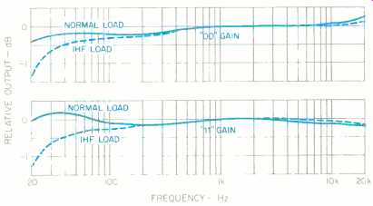
Fig. 1--RIAA phono equalization error for "00" (42-dB) and "11" (63-dB)
gain settings, with normal and IHF loads, at tape out.
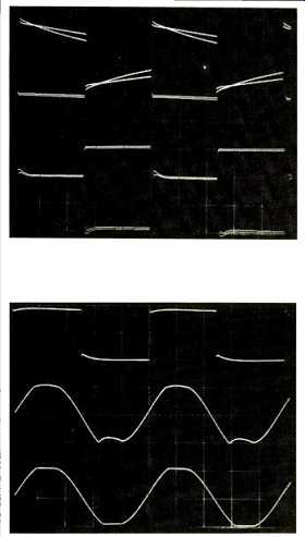
(top) Fig. 2--Phono-preamp square-wave responses at "00" gain
setting for 40 Hz (top), 1 kHz (middle), and 10 kHz (bottom). Dual traces show
effects of normal and IHF loads. (above) Fig. 3--Additional phono-circuit
waveforms. Large-signal square wave (top); sine-wave clipping character at "00" gain
setting (middle) and at "11" gain setting (bottom).
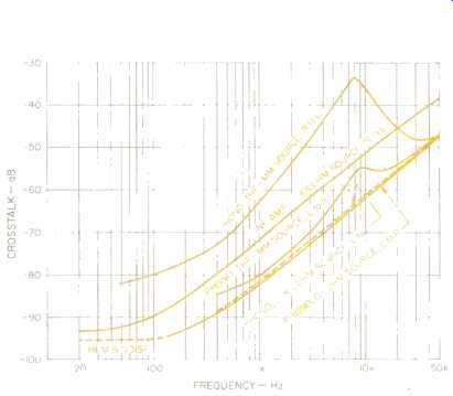
Fig. 4--Crosstalk vs. frequency for line and phono sections. Note that crosstalk
is shown in both directions for phono input with IHF-MM source (see text).
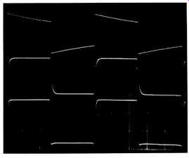
Fig. 5--Preamp line-amp square-wave responses for 20 Hz (top), 20 kHz (middle),
and 20 kHz at clipping (bottom).
Phono input impedance was representable by a parallel combination of 50 kilohms and 250 pF. Phono output impedance was about 600 ohms in series with 2.2 µF.
The line amplifier section was measured for THD + noise, which was found to be less than 0.01% from 20 Hz to 20 kHz at 7 V rms output with either a normal or IHF load. At 20 kHz with 7 V output, distortion was under 0.01% with up to 6,800 pF of extra capacitance loading. Although not recommended by MLAS, it was found that this line amp would drive 600 ohms at 7 V output with about 0.07% THD in the left channel and 0.04% in the right. The nature of this distortion was predominantly third harmonic and fairly constant across the audio band. Impressive performance! Rise and fall times of the output amplifier were 1.8 µS at ± 10 V output with either a normal or IHF load. Further, the rise and fall times were essentially constant with volume-control attenuation. With either or both balance controls set to +5 dB, the rise and fall times lengthened to 2 Another attribute of the circuit is that the rise and fall transitions stayed constant and exponential up to clipping.
A 'scope picture of square-wave responses through the output amplifier is shown as Fig. 5. The 20-Hz tilt in the top trace is caused by the 2.2-µF capacitor in the shunt feed back path. The bottom trace is for a 20-kHz square-wave signal overdriving or clipping the output amplifier.
AUX input impedance measured 14.3 kilohms in parallel with 300 pF. Output resistance was about 85 ohms.
Volume-control tracking was checked by setting the attenuation of the right channel in 5-dB steps and comparing the resultant attenuation in the left channel. Tracking error was within 1 dB to -65 dB, increasing to 2 dB at -70, 5 dB at -75, and 13 dB at-80, with the left channel always having more attenuation than the right.
Interchannel crosstalk of the line amp is shown in Fig. 4 Incidentally, crosstalk was in-phase for both the phono and line amplifiers.
A final measurement, of the unit's power-supply regulators, showed that correct voltage was maintained down to an a.c. line input of 95 V.
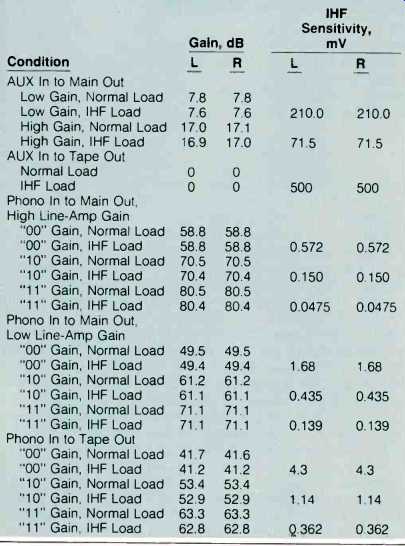
Table I--Gain and IHF sensitivity, ML-10A preamplifier.
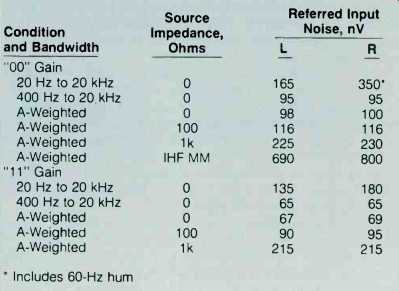
Table II--Phono noise, referred to input.
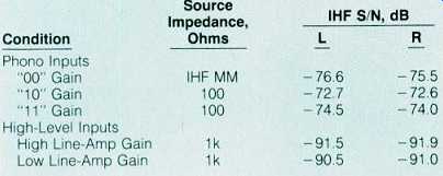
Table III--IHF signal-to-noise ratios, phono and AUX inputs.
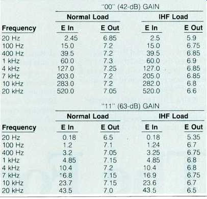
Table IV--Phono overload vs. frequency, loading, and gain (input values in
mV rms, output values in V rms).
Amplifier Measurements
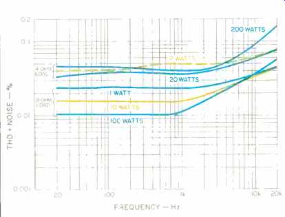
Fig. 6--THD + noise vs. frequency and power, ML-9 amplifier, with 4- and 8-ohm
loads.
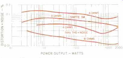
Fig. 7--THD + noise and SMPTE IM vs. power output, ML-9 amplifier.
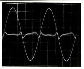
Fig. 8--Harmonic distortion products.
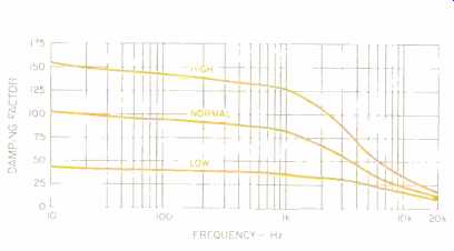
Fig. 9--Damping factor vs. frequency (re: 8 ohms) for three settings of damping
switch.

Fig. 10-Frequency response, ML-9 amplifier, at 1 watt output.
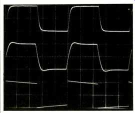
Fig. 11-Square-wave responses, ML-9, for 10 kHz into 8-ohm load (top), 10 kHz
into 8 ohms paralleled with 2µF (middle), and 40 Hz into 8 ohms (bottom).
The ML-9 was first run at 33% of rated power, or 33 watts per channel into 8-ohm loads, for one hour. Even though the heat-sinks got quite hot to the touch, the unit did not thermally cycle off during this test.
Voltage gain was found to be 19 x, or 25.6 dB, into 8-ohm loads with normal damping. IHF sensitivity for 1 watt output into 8-ohm loads was 150 mV.
THD + noise was measured for both channels for 4- and 8-ohm loads as a function of frequency and power output, and is shown in Fig. 6. The left channel had higher distortion than the right and is therefore the one plotted. Harmonic and SMPTE-IM distortion versus power output at 1 kHz are shown in Fig. 7. Figure 8 shows the harmonic-distortion products typical of a bipolar output stage with optimum bias. Lower bias (idling current) will produce a crossover notch, caused by gain reduction near the origin. Higher bias will produce a notch of the opposite polarity, caused by a gain increase near the origin. The "best" bias produces the dual-peaked "doublet" shape seen in Fig. 8. Distortion is affected by the damping switch, being lowest with the highest damping factor. For example, at 10 watts and 1 kHz, the left channel produced 0.036%, 0.015%, and 0.01% for low, normal, and high damping positions. In measuring distortion in this amp, I noted a thermal drift of bias which manifested itself in distortion dropping with time when power above about 10 watts was being produced. After running at higher power and returning to lower power, distortion would creep up to its former value at that lower power level after 5 to 10 S. I suppose one could term this thermal hysteresis distortion with a long time constant.
Damping factor was looked at as a function of frequency and damping-switch position. The specs for this unit claim damping factors of 100, 200, and 300 at 50 Hz, at a reference level of 1 watt into 8 ohms. I measure this by injecting 1 A rms from one channel into the measured channel. More specifically, one channel is driven to 8 V rms and connected to the measured channel's hot output terminal through an 8-ohm resistor. Then, to a good approximation, mV across the measured channel output becomes milliohms of output impedance. Results of this are plotted in Fig. 9. Using this method with other amplifiers, I generally measure about the same damping factors as claimed. Here, however, I got about half the specified values.
Frequency response at the 1-watt level for 4- and 8-ohm loads is shown in F g. 10. The slight difference in high frequency response for different loading is normal with most power amplifiers.
Interchannel crosstalk versus frequency was found to be better than-85 dB up to 10 kHz, rising to-80 dB at 20 kHz and- 74 dB at 50 kHz-excellent, indeed.
Rise and fall times were measured at ±5 V output into 8 ohms. As a function of the damping switch, the values were 5.0, 5.5, and 6.0 µS for high, normal, and low positions.
Large-signal square waves near clipping of the output started to slew slightly, in that the transitions became more straight-sloped than exponential. Nevertheless, the amp produced a large-signal rise and fall time at 100 V peak-to-peak into 8 ohms of 6 uS, for a slew rate of 80 V/6 1.13 or 13.33 V/uS. A 'scope photo of square waves through the ML-9 appears as Fig. 11: The top trace is 10 kHz into 8 ohms. The middle trace is 10 kHz into 8 ohms paralleled with 2µF; notable is the small amount of overshoot and ringing for this capacitive loading. The bottom trace is for 40 Hz.
IHF signal-to-noise ratio, which is A-weighted signal-to noise below 1 watt into 8 ohms, was -92 dB for the right and -95 dB for the left channel.
Dynamic headroom came out to be 5.3 dB, mainly due to the rated power of 100 watts and the burst power in this test of 340 watts/channel into 8 ohms. Clipping headroom was similarly high, at 4.55 dB, and is related to a continuous output at onset of clipping of 285 watts/channel into 8 ohms.
Use and Listening Tests
Camac connectors, although admittedly superior connectors per se, do cause interconnection problems in audio systems which use the usual RCA connectors. MLAS was kind enough to provide enough adaptors and interconnect cables using their silver wire to allow easy testing and system hookup of the ML-10A and ML-9.
Equipment used to evaluate the MLAS components included the following: Infinity air-bearing turntable and arm with a Koetsu EMC-1B cartridge; Audio Research SP10, conrad-johnson PV5 and GC/BHK preamplifiers: Audio Re search D70, Dyna ST-35, and Acrosound Stereo 20/20 power amps; Infinity RS IIA speakers, and Stax SR-X/Mk3 head phones.
I received the ML-9 some 4 or 5 months before the ML-10A, so I have had much more exposure to it. I must say that I liked this amplifier from the moment I first turned it on. I find the sound of the ML-9 to be smooth, detailed, and spacious, and without the high-frequency irritation present in most solid-state amplifiers. Surprisingly, it sounds similar to the Dyna ST-35, which is a highly musical-sounding little amp (when its ceramic input-coupling capacitor is eliminated).
Compared to the Audio Research D70, the ML-9 is smoother but not quite as revealing of musical texture, detail, and spatiality. Power and punch, it has plenty of-my ears gave up before it did. A critical friend to whom I loaned it thought it was the best solid-state amp he had heard.
Initial listening with the ML-10A was done using the Acrosound tube amplifier driving the Stax phones. Definition was very good, and bass quality and extension were outstanding, although "air" and spatiality were not as good as when the tube preamps were used. There was a noticeable bit of high-frequency edginess present. Subsequent discussion with MLAS indicated that it is really a good idea to warm up the ML-10A for a few days, with the phono inputs shorted or terminated with one's cartridge, before critical listening is attempted. Since the ML-10A is designed to be left on continuously, this warm-up would naturally occur in use.
After measuring the unit, I left it on for 5 days before listening again. The sound was definitely better this second time around, with reduced edginess noted.
Using the ML-10A and ML-9 as a combination on the Infinity RS IIAs yielded good definition and spatiality, but I was bothered by an upper mid- to high-frequency irritation.
Playing with cartridge loading didn't really help, but turning down the midrange and tweeter controls on the speakers did help a bit. When I would return to the SP10 preamp, for instance, the sound became easier and more musically natural. But then, since musical realism and naturalness in sound reproduction are so much a function of the total combination of elements, it might well be that other combi nations of components with the ML-10A would yield superior sound. It really sounded quite good on my headphones.
In summary, the Mark Levinson Audio Systems equipment reviewed here is attractive, solid, and very well-built and should have excellent reliability. As I have said before, the listening comments I have made are essentially my own opinions, and I emphatically recommend that the prospective purchaser go out and audition the equipment in as many circumstances as possible.
-Bascom H. King
(Source: Audio magazine, Aug. 1985)
Also see:
Mark Levinson No.20 Mono Amp (Aug. 1987)
Link | --Mark Levinson No.26 Dual Monaural Preamp (Aug. 1989)
Mark Levinson No.23 Dual Monaural Preamp (Apr. 1988)
= = = =