by MICHAEL GERZON
THERE SEEMS TO BE no doubt that in the long run, multi -channel stereo will become the standard for Hi-Fi. The real problem to be solved is how multi -channel sound can be recorded or broadcast cheaply and efficiently. The original Vanguard quadraphonic tapes cost $14.00 each for the usual LP length--which is too much. (Prices will come down with a rush when the demand increases). RCA have just announced that they will release a number of 4-channel tapes in August using the standard 8 track cassette but no prices are available as we go to press. Much work is going on behind the scenes to develop disk and tape systems which will be inexpensive and compatible and just what system will be finally adopted is anyone's guess at the moment.
One proposal involves the addition of two coded signals at 72 kHz and 92 kHz.
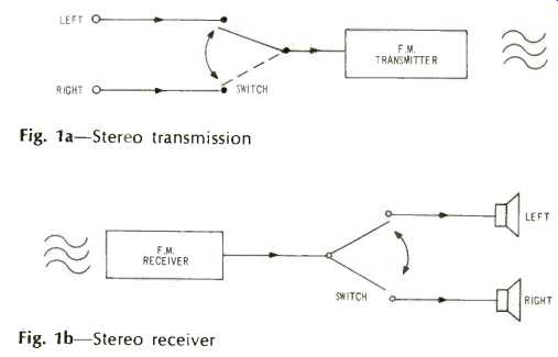
Fig. 1a--Stereo transmission. Fig. 1b--Stereo receiver
The main objections to this method are a rather low modulation level on all channels and a high noise level, poor frequency response (up to only 9 kHz) on the rear channels plus the difficulty of avoiding high -frequency chatter distortion. It seems to have been overlooked that there is sufficient room in the ordinary FM multiplex system to squeeze in a third or fourth channel without affecting the performance of present-day receivers. It is well known that the present method of broadcasting stereo does not allow audio frequencies above 19 kHz to be transmitted. Thus, the combined frequency range theoretically required by both left and right channels should be 2x38 kHz.
However, stereo multiplexing uses up a range of 3 x 19...57 kHz for each half of the spectrum. (In the U.S., the figures would be 53 kHz+53 kHz-ignoring SCA requirements, Ed.) It is in this 'surplus' 19 kHz that a third or fourth channel can be squeezed. The writer of this article has taken out a patent on such a system which is called QUART-meaning Quadrature Ambience with Reference Tone for 3 or 4 channels. First let us see how a 3 channel QUART is squeezed into a 'pint pot.'
In order to transmit two channels with a single transmitter (i.e., ordinary stereo ), a rapidly operating electronic switch--switches the left channel, then the right, then the left and so on, into the transmitter. See Fig. la. This switch operates at a very high rate (4 times 19,000, or 76,000 times per second) so that if the left- and right -channel electrical signals are as in Figs. 2a and 2b, then the switched signal fed into the transmitter might look like Fig. 2d. This is called the stereo multiplex signal. Figure 2c shows a square waveform which represents the way the switch is operating at each moment of time-the switching signal. As the switch in the transmitter functions at a high speed a listener picking up the broadcast with an ordinary mono receiver just hears the average of the two channels--a good mono signal. But in a stereo receiver there is a switch operating exactly in step with the one in the transmitter that switches the left and right signals into the two channels. How does the receiver switch keep in step? This is obviously very important and it is accomplished by a 19-kHz sine wave called the pilot tone which is transmitted by the station and the circuit is so arranged that the pilot tone keeps the switch synchronized (like an electric clock) . The QUART system adds a third channel using a system called "quadrature modulation" because it involves an additional switch operating exactly one quarter of a cycle out of step with the switch just described. A similar technique is used to convey color information in some TV systems. Consider a third rear channel audio signal which we will call the "ambience" signal as in Fig. 3a. Let the switching signal for stereo multiplex be represented by Fig. 3b. Now consider a second switching signal in quadrature with the first, i.e., a quarter of a cycle out of step with switching signal number one as shown in Fig. 3c. At the transmitter end, the ambience signal is made to modulate the quadrature switching signal; in other words at each moment we give the quadrature switching signal an amplitude proportional to the value of the ambience signal. If the ambience signal happens to be negative (as at time T in Fig. 3a) we then reverse the polarity (or the sign) of the quadrature switching signal also. By this means, we obtain a quadrature switching signal modulated by the ambience signal as shown in Fig. 3d.
Figure 6 shows the usual stereo signal plus the ambience-modulated quadrature switching signal as transmitted. To see how a receiver reacts to this complicated signal, consider a stereo receiver picking up a quadrature signal modulated by the ambience as in Fig. 6a. The switch in the receiver operates in step with the usual switching signal of Fig. 6b and the outputs of the left and right channels will be as shown in Figs. 6c and 6d. It will be seen that both these outputs are of a high frequency and will therefore contain no audio frequencies. Thus an ordinary stereo receiver picking up a QUART transmission will ignore the modulated quadrature switching signal and will respond only to the normal stereo signals.
A three -channel receiver using the QUART system will be similar to a conventional stereo receiver-plus a device to recover the ambience channel. The detector for the third channel will use switching similar to the switching used for stereo, except that it will take place in quadrature ( i.e. a quarter of a switching cycle out of step) with the stereo switching (see Fig. 5). As before, a pilot tone of 19 kHz is also transmitted to synchronize the receiver's switches with those at the transmitter. In the QUART system a low-level signal of 38 kHz in step with the stereo switching signal is also transmitted. This is called the reference tone and it helps in the synchronizing process as well as providing a signal to switch on a light for 3 -channel indication. While the QUART system is a little complicated to describe, it does have quite a few worthwhile advantages over other methods of adding a third channel. The most obvious advantage is that no frequencies over 57 kHz are transmitted in the multiplex signal-just as with ordinary two -channel stereo. This leaves plenty of room at higher frequencies for the broadcasting pf yet more channels. As the ambient channel uses frequencies in the 19- to 57-kHz range the amount of noise is much less than in other systems which use frequencies around 76 kHz for this channel.
Calculations indicate QUART three -channel transmissions should only be about 3 dB worse than conventional two -channel stereo.
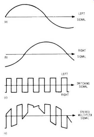
Fig. 2-Stereo multiplex signals
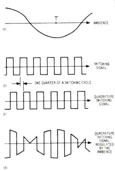
Fig. 3-Quadrature Ambience modulation
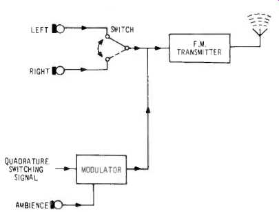
Fig. 4-QUART three -channel MPX transmitter
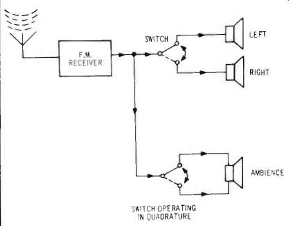
Fig. 5 -QUART three -channel receiver
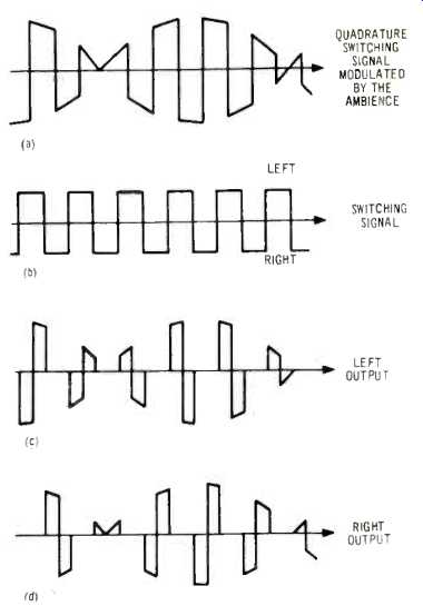
Fig. 6-Stereo reception of Quadrature Ambience
4-Channel QUART
By modulating frequencies around 76 kHz, it is possible to add a fourth channel and by careful adjustment of the various parameters it should be possible to ensure that the degradation of signal to noise is no worse than 7.5 dB-smaller than in any other system known to the author.
For those whose mathematics is good, the three -channel signal can be represented as follows:
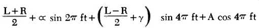
where L= the left channel signal, R-= the right channel, A the ambience signal, f= 19,000, t=time in seconds; cx and gamma are constants. The 4 -channel system can be represented as follows:
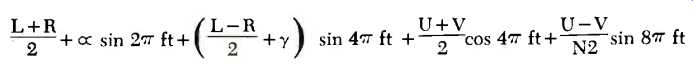
where U and V are rear left and rear right channel signals respectively.
This article has also appeared in the British "Hi-Fi News" and the author will welcome any correspondence on the subject of quadraphonic sound. The address is:
Michael Gerzon, Mathematical Institute, St. Giles, Oxford, OX1 3LB, England.
=============
(Audio magazine, sept. 1970)
= = = =