by Martin Clifford
SINCE ELECTRONICS is the warp and woof of our technological fabric, it is pleasant to think of electronics as new, something for which we, not our antecedents, can claim full credit. Not so! Electronics, or rather its progenitor, electricity, has an ancient and honorable history. The Greeks had a word for it--elektron--thousands of years ago, but it wasn't until 1897 that Sir J. J. Thomson first isolated the electron. An important step, but not a first one, for 20 years prior Heinrich Hertz had transmitted radio waves and some 40 years earlier Clark Maxwell had predicted their existence. Pushing time back a bit more, the word electricity was first used by Sir Thomas Browne in a book published in 1642. And around the time Caesar was invading Gaul, the Romans supplied the Latin base for electricity and electronics with their word "electrum." So much for newness.
One of the problems early investigators had is that electricity is one of relatively few forms of energy, existing as a rampaging force unless controlled. It was only divine providence and human ineptness that kept some of those early investigators of electricity from being electrocuted. Ultimately, prompted by relentless Nature, their research was channeled into two paths: how to generate voltages and how to control currents. With the advantage of 20:20 hindsight, we can see how electronic opportunity came knocking on many laboratory doors, only to be ignored.
One such was Thomas A. Edison whose mantle of inventive genius would have been even more lustrous had he but paused and listened. Busily occupied in 1883 with inventing the incandescent lamp, he placed a metal plate inside one of his bulbs and noted that when the metal was made positive with respect to the hot filament, a current flowed from filament to plate.
Something should have triggered a warning bell in Edison's mind, for he was witnessing the flow of electrons through the vacuum of space, not through a solid. Further, when he reversed the connections (Fig. 1) all current flow between the filament and the charged metal plate ceased. Current control with a vengeance, but only to be entered as an interesting experiment in a laboratory notebook, synonymous with being consigned to limbo. Edison had discovered the two-element tube, the diode, the keystone supporting today's science of electronics.
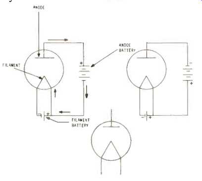
Fig. 1.--Basic diode symbol using a directly heated filament (A). When the
diode plate is made positive with respect to the heated filament (B), current
flows from filament to plate. If the battery connected to the plate is transposed,
current stops flowing in the plate circuit (C).
The Diode
The diode is a classic example of inventive simplicity at its best. A few pieces of metal placed inside a vacuum bulb and you have the first step toward radio, television, radar, and computers. How many can look at an acorn and see a tree?
Operation of the diode is as simple as its construction. When a wire, or other conductor, is heated, electrons on or near the surface are supplied with the energy needed for escape. In an ordinary electric light bulb they form a cloud (or electron space charge) around the filament with nowhere to go, possibly returning to the filament at some time. But with the insertion of a charged plate, subsequently known as the anode, the electrons now had a chance to move through space.
The Plate Current Path
Electrons in the cloud surrounding the filament, now urged on toward the plate, reach that haven, but promptly move on through the connecting wire to the plus terminal of the voltage source, a battery in this instance. This is not a terminus, for their trip isn't completed. They move through the interior of the battery, from the positive to the negative electrode, using the electrolyte between these two as a conductor. Emerging from the negative electrode they continue on through the connecting wire to the filament where they promptly receive another energy boost. And so the whole process is repeated as long as the filament is heated and the battery connected between anode and filament is in working order.
This current, called the plate or anode current, is unidirectional and nonvarying. That's not so important. What is breathtaking is that this current can be controlled. (Fig. 2). If the voltage between filament and anode is increased, the anode current increases. Not indefinitely, of course, but within reassuring limits.
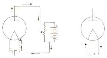
Fig. 2.--Current flow can be increased by raising the voltage on the anode
(A). The anode voltage can be changed by shunting a variable resistor across
the dc supply for the anode. The filament or heater current exists independently
of the anode current (C). The arrows represent the direction of current.
The Filament Current Path
Meanwhile, back at the filament, a battery, or other voltage source is busily driving a current through the filament. This current has a path completely independent of the plate current and so the diode is a two-current device. The only purpose of the filament current is to heat the filament, encouraging electrons to leave it. A filament current isn't really needed, for if the filament could be heated in some other way, the same objective would be reached. By a blowtorch, perhaps. Interesting, but not practical.
The Anode Return
The electrons constituting the anode current have a sole objective--a return to their starting point. And so the anode return, the wire connecting the anode battery to the filament can be attached to any convenient point on the filament battery's positive or negative terminal.
But doesn't this mean that some of the electrons forming the filament current and those of the anode current will become mixed? Hardly a problem. All electrons are alike, a pleasant fact that permits us to send more than one current through a wire and not worry about electron bookkeeping.
More Current Control
Another method of current control is to increase the temperature of the filament, by raising the voltage across the filament, sending more current through it. Moderation, as in all things, is required, for the filament can be made to glow to the point of complete burnout.
Indirect Heating
The filament can be heated by an alternating current supplied by a transformer. The problem here is that the voltage supplied by the transformer is a varying one, hence the current through the filament keeps changing. A fierce chain of cause and effect. The number of emitted electrons also varies, meaning the anode current follows in step. An unhappy situation for the current is doing something we don't want it to, and in that sense we have lost control.
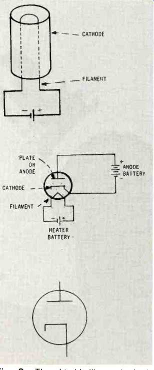
Fig. 3.--The thimble-like cathode is slipped over the heated filament, but
has no connection to it. (A); the cathode Ips isolate the anode and filament
circuits (B). Diode symbol using a cathode (C). In this symbol the filament
is omitted since its only function is that of a heater.
The solution is the difference between broiling over an open flame and using a frying pan. The modified diode now contains (Fig. 3) an element called a cathode. Heated by the filament, the cathode becomes the electron emitting source. The only function of the filament is that of a heater, and that is what such a filament is often called.
We now have two separate, distinct circuits, not connected ... the anode circuit consisting of the cathode, anode and the anode voltage source, and the filament and its voltage source. The cathode is simply a sleeve of electron rich oxides placed over, but not touching, the filament.
From A.C. to D.C.
The advantage of a.c. is that it lends itself so well to transmission over long distances. The voltage delivered to your home by your local power company is a.c., and so is the signal picked up by your receiver antenna. Not the same a.c., of course, but related. When delivered, it is often essential to be able to change that a.c. into some form of d.c., and it is in this circumstance that the diode shows its particular merit.
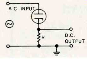
Fig. 4.--The diode can be used to change a.c. to varying d.c.
Fig. 4 shows a modified diode circuit. Two changes have been made. The anode voltage source is now a.c. and a part known as a load resistor is wired in series with it.
The a.c. voltage reverses its polarity regularly and so the anode is alternately made positive and negative. During the time it is positive, current flows from the cathode to the anode, through the load resistor and a.c. voltage source, back to the cathode. No current flows when the a.c. source makes the anode negative.
All of the anode current flows through the load resistor, but only in one direction. In doing so we have fulfilled the conditions for the production of a voltage. Every time a current flows through a resistor, a voltage develops across it. But the voltage, in this instance, is d.c. which varies in strength, but d.c. nonetheless. The diode circuit, then, can be used as a rectifier, a circuit that can change an a.c. input voltage into a d.c. output voltage.
The Basic Receiver
The process of changing a.c. to d.c. is called rectification. The same technique can be used in a rather crude type of radio receiver, but still a radio receiver, as shown in Fig. 5. Instead of using power line a.c., the a.c. is supplied by a radio signal. Other than that, the circuit functioning is the same. The diode used in this connection is referred to as a demodulator. Demodulation and rectification are synonymous; it is the diode applications that are different.
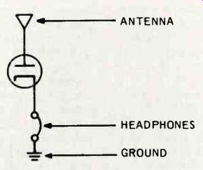
Fig. 5.--Complete radio receiver using diode, headphones, antenna and ground.
No sensitivity, no selectivity, no amplification, but it works. The filament
circuit is not shown, but is required for heating the cathode.
The radio receiver of Fig. 5 has no sensitivity or selectivity for there is no way of separating the various signals fighting for supremacy at the antenna input. And so what is heard in the headset, now used in lieu of the load resistor of the rectifier circuit, is a melange, a cacaphony of sound that would discourage anyone but a hi-fi enthusiast. A journey of a thousand miles starts with a single step, and the road to sophisticated music reproduction begins with a most elementary circuit.
Enter The Triode
Current control in the diode is effective, not sensitive. Ideally, it would be best if we could somehow poke a finger into the tube, directly in the path of electron movement between cathode and anode. An impractical thought having practical consequences, for where our fingers may not go, substitutes can be used. Such a replacement is a tiny bit of wire mesh or wire spiral, first inserted between cathode and anode by Dr. Lee de Forest in 1906. Originally called the Audion, but now known as a triode because the modified diode contains three electrodes: the cathode and anode, plus the new electrode, the control grid. (Fig. 6).
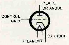
Fig. 6.--The triode is a three element tube containing a cathode (or possibly
a directly heated filament), a control grid, and a plate or anode.
The control grid, an ideal name for this element, is mounted close to the cathode and has the same general behavior as the anode. When the control grid is made positive, it exerts an attracting force on the electron cloud around the cathode. Although the distance between the cathode and the control grid is small, the electrons have considerable velocity by the time they reach the grid region. Unlike the anode, the control grid is mostly open space, and the majority of electrons hurl through to the anode, their inertia not permitting them to stop. Some electrons do impinge on the control grid structure, and, just as in the case of anode current, are returned directly to the cathode.
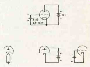
Fig. 7--The triode tube includes three circuits: the heater-cathode circuit
(A); the anode or plate circuit (B) and the control-grid circuit (C). Drawing
D shows these three circuits combined.
The Grid Circuit
The tube has now become the hub of activity for three different circuits. (Fig. 7). Two of these are the heater cathode circuit and the anode circuit. The new member is the grid circuit consisting of the cathode, the control grid, and the voltage source between the cathode and grid. Current moving in this circuit is appropriately called grid current. Not only does the triode encompass three different circuits, but each of these has its own voltage supply. The cathode has its filament voltage; the anode its anode voltage, while the voltage in the grid circuit is called bias.
If permitted to do so, water from a kitchen faucet, because of the tremendous pressure behind it, could easily flood any kitchen. Restraint is-imposed by a valve and so water flow can be governed from no water at all, to a trickle, to full force. In a comparable manner, the number of electrons moving from cathode to anode is measurable in the multi-millions, and so some electron restraint is needed. This is accomplished easily enough by putting a negative voltage, a small minus voltage, on the control grid (Fig. 8). This does not stop the movement of electrons from the cathode to the anode, but it does reduce their number to a controllable amount.
Cause and Effect
The physical closeness of the grid to the cathode makes it a most effective current control element, far superior to the anode working in the same capacity.
It is entirely possible for 1 volt on the grid to be as effective as 50 or more volts on the anode. As the control grid is made more negative, current flow is reduced. Conversely, as it is made less negative, current flow to the anode rises.
In the example just given, making the control grid more negative by 1 volt would reduce the current to such an extent that it could take an increase (in the positive direction) of 50 anode volts to restore the current to its original quantity. This ratio of anode voltage change to grid voltage change is called the amplification factor of the tube.
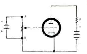
Fig. 8.--As the wiper arm of the variable resistor moves toward point A, the
voltage on the control grid is made more negative. Current flow from cathode
to anode is reduced. Current flow is increased by moving the wiper arm in the
opposite direction.
The Plate Cloud
An a.c. voltage-possibly the signal voltage from a sound source such as record player or tape unit-can be inserted in series between the bias voltage and the cathode of the triode. The effect of this a.c. voltage is that it increases and decreases the bias. At times the signal voltage adds to the bias; at other times it opposes it. As a consequence, the current flowing through the tube, the anode current, varies in step with the signal voltage input. To convert this changing current flow into terms of voltage, it is permitted to flow through a load resistor, as in Fig. 9. The voltage developed across the load will be a reasonably good replica of the signal voltage, but with an exception. It will be much stronger. Note that it is not the original signal voltage, but just a magnified version of it.
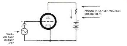
Fig. 9.--The a.c. voltage, in series with the bias battery, compels the current
through the tube to keep in step with it. This varying current flows through
the load resistor.
This amplified form of the signal can now be led into still another triode for further strengthening. The signal, by the repetitive process of amplification, can be made so strong that the footsteps of a fly walking across a microphone could be made to sound like the roll of distant thunder.
(To Be Continued)
( Audio magazine, Sept. 1972)
Also see:
The Language of High Fidelity--Part III: Basic Electronic Components (cont.) (Aug. 1972)
The Language of HIGH FDELITY: Part II--Basic Electronic Components (Jun. 1972)
The Language of High Fidelity--Part VII: The Basic High-Fidelity System (Dec. 1972)
The Language of High Fidelity--Part VIII (Feb. 1973)
Language of High Fidelity--Part XI (May 1974)
= = = =