John M. Lovda and Stephen Muchow [Sr. Development Engineers, Shure Bros, Inc. Evanston, III. ]
OVER THE PAST several years, the demand for clean, high level sound reproduction has brought the concept of biamplification into prominence among both audiophiles and professional sound men. In situations where the system amplifier is being pushed to its limits and the use of larger amplifiers could result in loudspeaker failure, biamplification provides a means of achieving low distortion sound and high acoustic sound pressure levels. If the desired acoustic output level can be achieved without overloading the amplifier, as is the case with most home high fidelity systems, biamplification is unnecessary. However, even these systems can benefit from biamping in terms of higher sound pressure levels with lower distortion.
This article will focus on situations where biamplification is useful by describing some of the theoretical and practical advantages of this approach to achieving high sound pressure levels. Several objective and subjective experiments will be described which were performed in an attempt to determine optimum amplifier power ratios and crossover frequencies. The results of this work provide insight as to why biamplification can improve performance. Finally, a typical sound reinforcement system will be described for use in high sound pressure level applications.
Single Amplifier System
A conventional arrangement consisting of a single amplifier feeding a multi-driver loudspeaker system is shown in Fig. 1. The output of the amplifier is fed into a passive large signal crossover network which contains a low-pass filter, high-pass filter, and (usually) a high frequency attenuator. In many home high fidelity or studio monitoring systems, a mid-range loudspeaker and crossover section is also found.
The corner frequencies and rolloff slopes of these crossover filters are optimized to match the acoustic characteristics of the loudspeakers and to protect the speakers from signal frequencies which may be potentially damaging. The most common area for concern regarding loudspeaker danger is the resonance frequency point of high frequency drivers.
Depending on the internal damping of the diaphragm, signals in the resonance region can cause excursions of excessive magnitude, resulting in physical destruction. To minimize this problem at high operating levels, high- and mid frequency crossover networks should be designed with skirts that are sufficiently steep to keep the acoustic output of the driver in the resonance region at least 20 dB below the normal passband level.
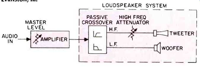
Fig. 1-Single amplifier system.
The output of the high-pass filter normally connects to a resistive attenuator, providing level adjustment for the tweeter to attain a desired acoustical balance. This attenuator is usually a T or L pad constructed either with a stepped or a continuously-variable resistive network. Because high-frequency drivers are typically more efficient than low-frequency speakers, some attenuation is usually necessary.
The basic advantage of the single-amplifier arrangement is simplicity-one amplifier and speaker system are the only components required. There are several major disadvantages, however, if the system is to be operated at high acoustic output levels.
First, the crossover components, including the high-frequency attenuator, must be specially selected for high-power use. Capacitors are usually metalized mylar, non-polarized types. For sound reinforcement applications where high peak-output power is the rule, the capacitors must also have high breakdown-voltage ratings (100 volts or higher) and low dissipation factors (typically less than 1% at 1 kHz). Capacitance values as high as 504 may be necessary if the system is designed with four-ohm speakers and a low crossover frequency.
Inductors can be either air or iron core but must not saturate. The wire gauge in the coil must be sufficiently large to keep the Q high and reduce power loss to a minimum.
The power resistors or rheostats used for the high frequency attenuator are usually wire-wound devices of high wattage rating. This is necessary because the sensitivity of the tweeter must be reduced to match that of the low-frequency speaker by dissipating the power difference in the resistors. Tapped auto-transformers can be used as high-frequency attenuators and in this application provide very low loss. However, they must also be large enough to avoid saturation and are more expensive than resistors.
A second disadvantage is related to the generation of distortion components during amplifier clipping. Consider first a high-amplitude, low-frequency signal. Should the level become large enough to clip the amplifier, high-frequency distortion components will be generated whose frequency distribution is dependent upon the degree of clipping. Conversely, if high-level, high-frequency information is presented in a pulsed fashion causing the amplifier to clip, low-frequency distortion components will be generated at multiples of the pulse rate. (This was discussed by C.R. Anderson and P.W. Jenrick in "A Practical High-Frequency Track ability Test for Phono Pickups," Audio, August, 1972, pp. 3436.)
Biamplified System A biamplified system consists of a low-level passive or active crossover network and two power amplifiers (see Fig. 2). The incoming low-level signal is first split into low- and high-frequency bands and then routed to separate power amplifiers. These amplifiers are directly connected to their appropriate low- and high-frequency speakers. Although it is not a necessity, a properly designed speaker system for biamplified use should have some means of high-frequency-driver protection. This circuitry will help prevent failure due to reverse hookup of low- and high-frequency speakers, amplifier turn-on transients, and amplifier failures. Although the cost of the biamplified system is greater due to the addition of a second power amplifier, several advantages result.
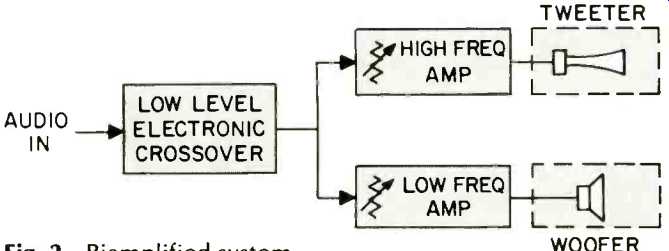
Fig. 2-Biamplified system.
First, a large degree of circuit design flexibility is allowed because the crossover network operates at low signal levels and is terminated by the high input impedances of the power amplifiers. With a passive biamp crossover design, components with reduced size and power-handling capabilities can be employed. High-value, low-loss, expensive capacitors are unnecessary because of the increased termination impedance. If an electronic crossover is used employing active filters, inductors can be eliminated completely. Active filter design also permits the use of filters with extremely steep roll-off rates when necessary, at reasonable cost and circuit complexity. One commercial design employs a novel circuit in which the high-pass signal is directly obtained by filtering, and the low-pass signal is derived by taking the difference of the input and the high-pass signals. Regardless of component tolerances, the high- and low-frequency outputs of this circuit complement each other exactly in the crossover region. Crossover frequency selection can also be accomplished with a minimum amount of component switching.
The second advantage is the ability to assign different power output capabilities to the two frequency bands. By matching the peak-voltage capability of the amplifier with the recommended maximum voltage rating of the driver, transient program peaks and noise spikes will be clipped and limited to a safe value. This protection is provided regardless of gain settings of the previous stages or the voltage levels present at the low frequency speaker. The use of "super" amplifiers or bridged pairs of amplifiers connected to a single amplifier system cannot provide this safety factor without external speaker protection circuits. In many applications, small high-frequency amplifiers can be used without compromising system performance. As will be shown later, this requirement relates directly to loudspeaker efficiency and crossover frequency selection.
The ability to drive an unlimited number of power amplifiers using one crossover network is another advantage of a biamplified system. This arrangement is possible when using power amplifiers with high input impedances. This added bonus becomes very economical in large sound-reinforcement applications.

Fig. 3-Setup for biamplified peak-level test.
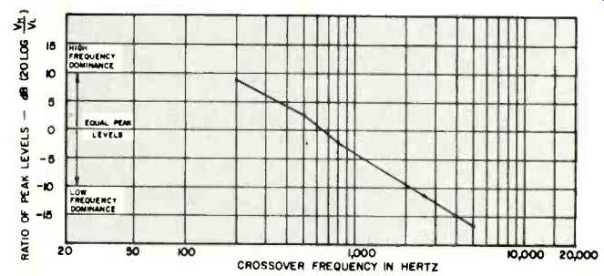
Fig. 4-Ratio of high (VH) and low (VL) frequency peak levels vs. crossover
frequency for program material with heavy high-frequency content.
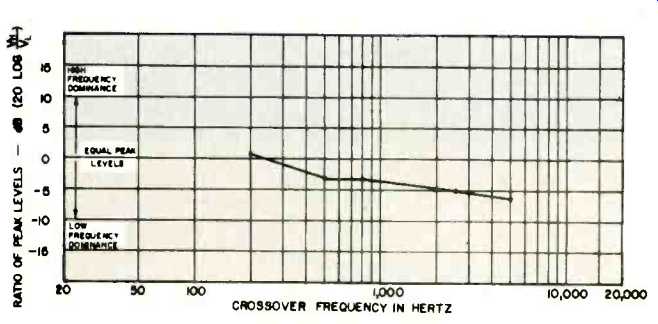
Fig. 5-Ratio of high (VH) and low (VL) frequency peak levels vs. crossover
frequency for program material with even frequency content.
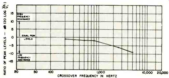
Fig. 6-Ratio of high (VH) and low (VL) frequency peak levels vs. crossover
frequency for program material with heavy low-frequency content.
In terms of acoustical benefits, perhaps the most widely discussed advantage of biamplification is the ability to attain higher sound pressure levels without clipping than with a single amplifier of comparable size. Consider a composite signal with 250-Hz and 10-kHz components and assume the low-frequency component is twice as large as the high-frequency component. If this signal is fed to an amplifier with a 40-volt peak-output capability, the low- and high-frequency components could only reach peak levels of 26.7 and 13.3 volts respectively before clipping. Bi-amplifying the system, two amplifiers capable of 26.7-volt peak and 13.3-volts peak, respectively, would provide the same undistorted output level with this test signal. Converting these peak voltages to rms values and assuming an 8-ohm speaker system, this suggests that a power amplifier capable of producing 55.6 watts (44.5 + 11.1) provides the same performance as one with a rating of 100 watts. When the low-frequency amplifier clips, the harmonically-related distortion products are isolated to the low-frequency speaker only. These products will be naturally attenuated somewhat by the response roll off of the woofers at high frequencies due to the voice coil inductance.
Impressive as the previous power comparison might appear, realistic wide-range musical signals present a more complex problem to the sound system designer. Although no exact formula exists for specifying biamplified system parameters, it seems apparent that crossover frequency, power amplifier size, and musical spectral characteristics must be interrelated. The following experiments were designed to examine the relationships among these variables and to determine basic guidelines for use in designing and optimizing practical biamplified systems.
Bi-amplified Peak Levels
An experiment was performed in which three spectrally different types of program material were analyzed electrically. The program material for the experiment was separated according to three classifications: heavy low-frequency content, heavy high-frequency content, and that which had an even-frequency distribution. Selections from records were used for the low- and even-frequency distributions, while a tape recording of a female vocalist in a live performance was used for the sample with the heavy high-frequency content. Because this program material would be used later in a listening test, all three program sources were subjectively matched for overall level, and carefully recorded on a tape for convenience and repeatability. Before analysis, the output of the tape was first separated by an electronic crossover with switchable crossover frequencies of 200, 500, 800, 2600, and 5000 Hz. The signal output was then measured with a peak-responding meter and storage-type oscilloscope, so that it was possible to visually observe as well as measure the peak output-voltage characteristics. Peak voltage measurements were made at both the low- and high-frequency outputs as shown in Fig. 3. Using this equipment, the peak voltage within a chosen spectrum could be measured and tabulated. Graphical representations of the measured results are shown in Figs. 4, 5, and 6.
The curves plotted represent the numerical difference between the low- and high-frequency peak levels expressed in dB, with 0 dB on the graph corresponding to equal low- and high-frequency peaks. The dB values on the vertical axes represent the voltage or power ratios that would be required for uniform clipping of both the high- and low-frequency bands at various crossover frequencies. These ratios all assume identical sensitivities and impedances of both speakers. As expected, the slope of the curve in all cases indicates that low-frequency peak energy is greater than high frequency peak energy when the crossover frequency is shifted upward. The converse is also true, with the point of equal distribution located at approximately 300 Hz for the low- and even-frequency distribution material and approximately 700 Hz for the material with high-frequency predominance. These results seem to indicate that to efficiently bi-amplify wide-range program material using identical power amplifiers, a 300-Hz crossover frequency should be used. It can also be seen from these graphs that as the crossover frequency is shifted upwards, for example to 2600 Hz, the high-frequency peaks are as much as 6 dB lower.
This indicates that the high-frequency power amplifier used could be smaller, requiring approximately one half the clipping-voltage capability of the low-frequency amplifier.
Conversely, the low-frequency amplifier requires a clipping level 6 dB higher than the high-frequency amplifier to faithfully reproduce wide range material. From these results, a theoretical minimum high- to low-frequency ratio may be determined at various crossover frequencies for a given type of program material.
The results of these measurements could be interpreted as a guide for determining amplifier power ratios as a function of crossover frequency. Our experience, however, has shown that substantial amounts of low-frequency as compared to high-frequency clipping are normally tolerable without any apparent deterioration of sound quality. This tolerance to clipping prompted two psycho-acoustical experiments to gain additional insight into actual power amplifier requirements for biamp operation.
The first of these experiments was designed to provide information regarding power ratios vs. crossover frequency. A switchable biamp system was devised whereby the listener could compare an undistorted signal with a signal distorted in either the high- or low-frequency section only. Figure 7A shows the setup used for low-frequency clipping, while Fig. 7B shows the setup used for high-frequency clipping.
Amplifiers A and B were both operated well below their output-clipping points. These amplifiers made up the undistorted system. These amplifiers made up the undistorted system. The clipping point of amplifier C was made continuously variable from 8 to 40V rms by means of a variable auto transformer on its a.c. power line. Prior to this test the distortion characteristics of this amplifier were verified to be uniformly low over the range of adjustment. Amplifier D was introduced so that the listening level could be easily adjusted while maintaining a predetermined clipping level.
The two low-pass filters shown at the outputs of amplifiers B and C in Fig. 7A were provided to simulate the normal high frequency rolloff typical of low-frequency loudspeaker sections. This filter had a 6-dB-per-octave rolloff slope with the corner frequency located above the crossover point.
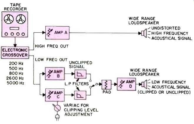
Fig. 7a-Experimental setup for low-frequency clipping psychoacoustic test.
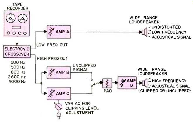
Fig. 7b-Experimental setup for high-frequency clipping psychoacoustic test.
During each experiment, the test subjects were asked to lower the clipping point in amplifier C, while comparing it to the unclipped amplifier B until a difference or increase in audible distortion was noted. By combining the results of each experiment, a high-to-low-frequency power ratio was determined for each test subject. Several interesting phenomena were noted from the data obtained. First, the variance of listener tolerance to distortion was quite wide. Some people would accept substantial clipping on peaks and make judgments on average levels only, while others appeared to be sensitive to the slightest differences. This variance was more severe on the live recording which exhibited the highest peak-to-average ratio. Second, with the selection of either a 200-Hz or 500-Hz crossover frequency, low frequency distortion was essentially inaudible, even with the signals substantially clipped. The bass content of the program would subtly diminish as the clipping became increasingly severe, and only at extremely low clipping voltages would intolerable distortion occur. These observations make sense when one considers that the low-frequency loudspeaker system tends to roll off higher-frequency distortion components. In addition, those high-frequency distortion components that are reproduced are masked by the output of the high-frequency loudspeaker section. This effect diminished as the crossover frequency was raised, but was noticeable for all but the 5-kHz crossover setting.
Considering the degree of clipping observed on an oscilloscope during these tests, it is apparent that biamplification provides a psychoacoustical means of reducing perceived distortion. The power ratios observed followed the same general trend as was previously measured electrically, but the large variation between listeners suggested that an average curve would be of little value. The data presented in Figs. 4 through 6 consequently represent reasonable guidelines for determining amplifier power ratios.
The second experiment was designed to measure listener tolerance to clipping distortion. For this test, the subjects were repeatedly presented the same musical cut and asked to rate the fidelity according to a list of five performance criteria ranging from very clean (unclipped) to very distorted (clipped). Each time the selection was repeated, the low-frequency clipping point was changed in a random fashion while the high-frequency channel remained clean. Five output-voltage clipping levels, spaced 6 dB apart, were selected. During the course of the experiment, each level was used twice to establish if listeners had any measure of repeatability. An unclipped selection was played first as a listener reference and was reinserted later in the random sequence.
As in the last experiment, listeners' opinions varied widely as to the quality of the selections. The ability of the individual to correctly match two selections with the same clipping level when separated by time was rather poor. There was a tendency to be conservative, rating the clean and slightly distorted passages as fair and only the most heavily clipped selections as poor.
As part of the experiment, the unclipped high-frequency channel was shut off and the listeners were able to compare the apparent distortion level of the clipped amplifier alone.
In almost all cases, the amount of distortion perceived increased dramatically when the clean high-frequency signal was removed. This provided further verification that the unclipped channel has a psychoacoustically beneficial masking effect on the distortion products generated by the clipped channel. This effect was greatest at lower crossover frequencies but continued to be substantial even at the highest crossover frequencies. Considering the fact that many sound-reinforcement amplifiers used for high-level applications are clipped a large percentage of the time, this masking effect is most likely the underlying reason for the subjectively lower distortion sound quality and increased levels available when a biamplified system is used.
Summary
When designing sound systems for high-level music reproduction, proper consideration of the effects of masking and high-frequency-driver power limits will produce the desired combination of low distortion and high reliability.
The following steps should be considered in order to determine the correct amplifier sizes for a biamp system:
1. The crossover frequency, power handling capabilities, and sensitivities of the various loudspeaker sections should be noted.
2. Figures 4 through 6 should be reviewed with some feeling for the type of program material to be reproduced. Based upon this review, a power ratio should be determined.
3. The above ratio should be modified in accordance with any differences in the sensitivities of the loudspeaker sections being used.
4. The power amplifier sizes are then computed based on the specific sound passages required for the application.
5. If the above power requirements exceed the system capabilities, additional speakers, more efficient speakers, or a change in crossover frequency should be considered.
It should be pointed out that most wide range systems capable of biamplified operation have been optimized for the crossover frequencies stated and degradation of performance or physical damage might result if the crossover frequency is changed.
Figure 8 shows a typical large sound reinforcement system used for wide range program material at high sound pressure levels. The system consists of one electronic crossover with splitting frequencies set for 2600 Hz, five power amplifiers each capable of 28V rms output, and four 16-ohm, wide-range portable loudspeaker systems. One amplifier drives all four high-frequency sections at a maximum of 50 watts each. The high-frequency level can be easily adjusted using the amplifier gain control. The four low-frequency amplifiers are connected to form two bridged-pair (series connected) amplifiers, with each pair capable of providing 200 watts (57 V rms) to each low-frequency system. A detailed wiring diagram of a bridged pair is shown in Figure 8B. The inputs to the amplifiers are parallel connected out of phase with each other and the outputs are series connected.
This arrangement provides twice the voltage swing and four times the power output of a single amplifier. Both output terminals are floating above ground and must not be connected to the chassis. Note that each low-frequency speaker can receive more power than its matching high-frequency driver, while still providing isolation to the high-frequency drivers from 80 V spikes. The sound system could easily be expanded by connecting additional amplifiers and loudspeakers to the crossover outputs.
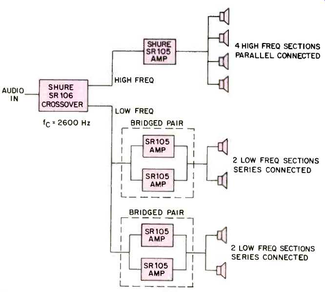
Fig. 8A-Typical biamplified sound reinforcement system for high SPL operation.
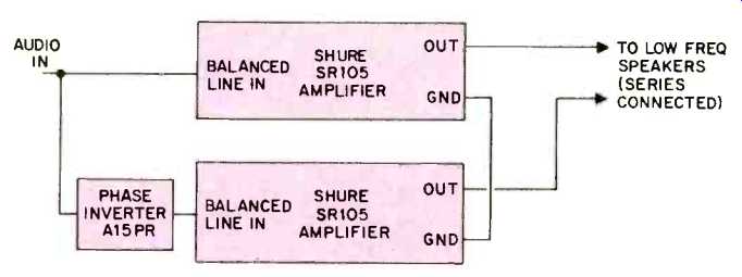
Fig. 8B-Bridged-pair wiring scheme.
Conclusions
In conventional wide-range sound reinforcement systems, where single amplifiers are often driven into clipping, the use of biamplification techniques can be beneficial.
Biamplification offers audibly lower distortion, decreased amplifier power requirements, and increased speaker protection. The reduction in apparent distortion in a properly designed biamp system is in part due to the high-frequency rolloff of the low-frequency speaker section and to the masking of low-frequency distortion products by clean high-frequency program material.
Peak program measurements indicate that the peak-voltage distribution in the high- and low-frequency bands of a biamplified system are nearly equal at crossover frequencies between 200 Hz and 500 Hz. As the crossover frequency is increased, the peak program content in the low-frequency band increases while the high-frequency peak program content decreases. At higher crossover frequencies, the power demands placed on both the high-frequency amplifier and speaker are reduced. This decreases the chance of high frequency speaker damage.
Biamplification also offers non-acoustical advantages such as flexibility of crossover network design, ease of system expansion, and simplified means for level adjustments of both be low- and the high-frequency sections. It is readily apparent that biamplification offers many advantages worthy of serious consideration in the area of high sound pressure level sound systems.
(Audio magazine, Sept. 1975)
Also see:
Power Amplifiers and the Loudspeaker Load: Some Problems and a Few Suggestions (Aug. 1977)
Transient IM Distortion in Power Amplifiers (Feb. 1975)
= = = =