
MANUFACTURER'S SPECIFICATIONS
Power Output: Minimum of 200 watts per channel into 8 ohms or 125 watts per channel into 16 ohms, both channels driven, 20 Hz to 20 kHz, with less than 0.05% total harmonic distortion or intermodulation distortion. Input Sensitivity: K-ohms. Rise Time: At 8 ohms, better than 2 MS at full power to 20 kHz, slew rate equal to 40V per µS. Noise: Better than 100 dB below full power, unweighted, wide band; 112 dB below full power, wide band with r.f. filter. Size: 17 1/2 in. W. x 7 in. H. x 9 in. D. Shipping Weight: 50 lbs. Price: $599.00, kit.
Ampzilla is the first product of a new audio company--The Great American Sound Co. It is different and unusual in appearance and quite attractive after one gets used to it. It is available as a kit or factory wired; the unit reviewed was factory wired.

Fig. 1-Rear view of G.A.S. Ampzilla.

Fig. 2-Internal view.
Refer to Figs. 1 and 2. The package is rugged, solid, and relatively simple. A U-shaped bottom piece serves to mount the power transformer, two filter capacitors, cooling fan, heat sink chimney assembly, and some of the normal front and back panel components. The chimney has the two power-amp circuit boards mounted on opposite sides, with four output transistors at the bottom on each side below the circuit boards. The fan is powered from the main secondary winding of the power transformer. Operating at a low-medium speed, it is reasonably quiet, as fan-cooled amps go.
The rectifier bridge and four supply fuses are mounted on a bracket that connects the ground sides of each filter capacitor to the chassis ground.
On the front part of the bottom chassis piece is a three position phase-reversing power switch (Off/On/Off), two speaker-line fuses, and a green LED Power On indicator. On the back part of the main chassis are the line cord, line fuse, two sets of binding posts for the outputs, and a pair of phono jacks for the signal inputs.
Ampzilla has a front protrusion housing the meters and meter switch. In both cases, white end caps, contrasting with the black anodized chassis pieces, fit over the ends of the U sections and are solidly screwed to them to hold the whole unit together. Pemm nuts and machine screws are used throughout Ampzilla, with no self-tapping screws used anywhere.
The meters are calibrated in rms watts into eight ohms with a sine wave and relative dB, with 0 dB equal to 200 watts. The meters are average-responding and appear to have somewhat faster ballistics than a standard VU meter. As this reviewer has mentioned before, decade range switching is very desirable for easy reading of power on the lower ranges, and a 200-milliwatt full scale is a very handy reminder of the fact that a lot of listening on efficient speakers takes place down in the 1-100 mW region.
Circuit Description

Fig. 3-Circuit schematic.
As can be seen in Fig. 3, the circuit of Ampzilla is full-complementary from input to output. The input stage consists of a dual-complementary differential amplifier, Q1-4. The output of Q1 drives Q6, a PNP emitter follower. Q6 drives Q7 which is a PNP inverting gain stage and is the plus predriver.
In a similar manner, Q3 drives Q8 and Q9 with Q9 being the negative predriver. Q7 and Q9 operate Class A, with a quiescent current of about 25 mA. The signal currents at the collectors of Q7 and Q9 are in-phase but even harmonics are out of phase and will tend to cancel out. These collectors are tied together through the bias regulator. The pre-drive signal is thus relatively free of even harmonics and can drive the output stage equally hard in both directions. The bias regulator is a special integrated circuit designed to accurately control the idling current of the output stage as a function of temperature. The IC is mounted with its top surface in good thermally greased contact with the bottom of the heat sink where the output devices are.
The output stage is effectively a complementary follower with emitter-follower drivers. Each driver and output composite device is made up of two transistors in series to increase the safe area of the output stage. The inner drivers and outputs (Q13, 14, 17, 18) are driven from the pre-drive signal, while the outer devices (Q12, 15, 16, 19) are driven as slaves via voltage dividers from the amplifier-output signal.
These signal dividers cause the voltage across the series connected transistors to remain equal over the entire signal cycle.
The emitters of Q17 and Q18 are connected to the output buss through relatively large (0.39 ohm) emitter degeneration resistors that are paralleled by Shottky rectifiers.
This assures good thermal stability of the output transistors with minimum drop at high current due to the low forward drop of the paralleling rectifiers. Turn-on thumps are eliminated in this design by causing the emitter currents, and hence the subsequent stage currents, of the input pairs to be zero at turn-on and then to slowly come up to the operating value. This is accomplished by the action of the voltage regulator consisting of Q5, D5, C9, and R18. Upon turn-on, C9 is uncharged and current flow from R19 through R18 down to R20 turns on Q5 causing its collector-to-emitter voltage to be about 0.7 Vg and at about ground potential.
As C9 charges slowly, due to the time-constant multiplication effect of Q5, the collector-to-emitter voltage of Q5 increases to its ultimate value of about 52 V when D5 conducts. When this point is reached, the collector will be +26 V and the emitter will be at-26 V, supplying about 3.3 mA to each differential pair. When D5 is in conduction, the voltage drop across the regulator will be constant with changes in line voltage and therefore the emitter currents of the input differential amps will remain constant. A cute circuit trick! The protection circuit is of the volt-amp (VI) type, sensing both current and voltage in the output stage. If voltage and/or current are considered excessive, Q10 or Q11 will conduct, reducing the current in Q7 or Q9 and hence the output drive. This action of reducing the current in the pre drivers is unusual and desirable, and is in contrast to the usual practice of shunting the drive current from pre-drivers through the protection devices into the output buss.
The power transformer is appropriately large and beefy and has unusually good voltage regulation. Filter capacitors are two 16,800 µF units. Output voltage at idle is about ± 75 V d.c.
Listening Tests
This reviewer has spent a lot of time listening to Ampzilla, having had one for several months. Speakers have included the reviewer's own arrays, Dalhquist DQ-10s, and Magnepan MG-2167Fs. The conclusion is inescapable. Ampzilla is the best sounding commercially available bipolar solid-state amplifier heard so far. The low end is incredibly tight and solid, the mid range clean and defined, and the high end is light, airy and virtually free of edginess and grit. When listening in comparison to other good solid-state amplifiers, there is a feeling that their sound isn't as transparent and that an amplifier per se is more identifiably in the reproducing chain.
Measurements

Fig. 4-Upper curve, THD versus power into 8-ohm load (use right-hand scale);
lower curve, total IM and sum of 5 th & 7th versus power into 8-ohm load
(use left-hand scale).

Fig. 5-Upper curve, 1-watt frequency response into 8-ohm load, note break
in curve at 100 Hz to 10 kHz; lower curves, THD versus frequency at various
power levels into 8-ohm load.
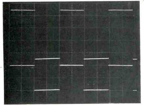
Fig. 6-50-Hz square waves; upper trace, 200 watts into 8 ohms (scale 20
V/cm, 5 mS/cm); lower trace, 3.12 watts into 8 ohms (scale 5 V/cm, 5 mS/cm).

Fig. 7-10-kHz square waves; upper trace, low power into 8 ohms (scale 5
V/cm, 20 µS/cm); lower trace, low power into 2 µF (scale 5 V/cm, 20 µS/cm).

Fig. 8-Upper trace, 20-kHz full-power square wave into 8 ohms, 80 V P-P
note text (scale 20 V/cm, 10 NS/cm); lower trace, 20-kHz sine wave, 200 VA
into 1 pF, 40 V rms, THD 0.25% (scale 10 µS/cm).

Fig. 9-Upper trace, 20-kHz, 80 V P-P square wave into 1µF load (scale 20 V/cm, 10 µS/cm); lower trace, 20-kHz sine wave into 8 ohms with 2 dB overdrive (scale 50 V/cm, 10 µS/cm).

Table I-Output noise
Ampzilla was first run for one hour at one third power, or per channel, with continuous kHz test tone. It for 10 kHz square waves at low power into eight ohms and 2µF loads. These responses are typical of most amplifiers that have been reviewed. Fig. 8 illustrates the response with a full-power 20kHz square wave into eight ohms and a 200 VA 20 kHz sine wave into a 1µF load. (The slight ringing on the +1/2 cycle is mostly due to a slight aberration on the output of the pulse generator used.) The measured rise time for the square wave is about 3.2 µS and the slew rate is about 20 V/µS. THD for the 200 VA sine wave is about 0.25%. Fig. 9 shows the response to a 20-kHz 80 V p-p square wave into a 1µF load and a 20-kHz sine wave into eight ohms with a 2 dB input overdrive where the input is increased 2 dB over the value that just causes the output to begin to clip The large signal square wave indicates the amplifier's ability to deliver in excess of 10 amps into a 1µF load.
This qualifies it as a third amplifier in this reviewer's experience that can deliver such a fast large signal into a capacitive load. The response to the 20-kHz overdrive signal is outstanding. Virtually every other solid-state amplifier "sticks" on high frequency clipping. ["Sticking" is where the squared-off portion, when clipping, lasts longer than it should and then suddenly jumps toward zero vertically or very quickly and then finally gets back into the sine wave slope after recovery from clipping.] It is believed that how a power amp clips at high frequencies has some effect on how the amplifier sounds when not clipping. Amps that clip cleanly and don't stick generally do sound better, all other standard measurements being about the same. Damping factor was measured as a function of frequency and found to be about 160 from 20-300 Hz, decreasing smoothly to about 154 at 1 kHz, and 28 at 20 kHz.
Output noise as a function of measurement band-width with inputs shorted is shown in Table 1 below. The highest noise voltage in the 20 to 20 kHz band is about 102 dB below 200 watts into eight ohms and is composed mainly of lower order line harmonics.
In summary, Ampzilla is unquestionably in the state-of-the-art class and takes its place among a small group of fine amplifiers that really do make reproduced music sound more like live music.
-Bascom King
(Audio magazine, Sept. 1975)
Also see:
Fisher RS-Z1 Receiver (Aug. 1990)
Yamaha CA-1000 Integrated Amplifier (Sept. 1974)
Link |
= = = =