by GRAHAM BANK
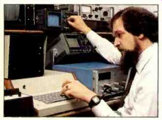
above: Graham Bank is the Technical Director for Celestion International, Ltd. in
Ipswich, England and is responsible for the company's research, including the
design and development of loudspeaker systems for professional and home use.
For the past 50 years, the moving-coil speaker has probably changed least of all major audio components and we have learned very little about basic speaker behavior during this period.
Essentially, a speaker is a sound producing vibrator which attempts to recreate, mechanically, the sound waves made by a person's voice or a musical instrument. The goal of a manufacturer is a speaker which correctly imitates the vibrations of live sound.
But if the vibrations cannot be seen or measured, how is it possible to make sure they are mechanically correct? Until recently, the measurement techniques for evaluating speaker performance have been indirect, analyses of the sound created rather than of the process that results in the sound waves. The most famous of these indirect measurements is, of course, the amplitude response curve. Using microphones in an anechoic chamber, this test gauges the sound pressure of a speaker's output across the audible frequency range. Ideally, a speaker should emphasize all frequencies equally, resulting in a "flat" response curve and, theoretically at least, reproducing all of the music signals with perfect accuracy.
However, if a speaker flunks its amplitude response test, showing a curve that resembles the jagged peaks and valleys of an EKG, the designer still does not know the reason for the failure. Furthermore, even if the speaker produces a perfectly flat response curve, that's no guarantee that it will actually sound good. How many times have you read a review of a speaker--or heard one--whose musical performance flew in the face of the tests? Also, quite frequently two speakers with similar amplitude response curves sound completely different.
For years, scientists sought a more direct way to evaluate speaker performance. Early experiments included dumping lycopodium powder onto operating loudspeakers and then observing the patterns that developed on diaphragm surfaces with a stroboscope, techniques borrowed from general theories on vibrating bodies. Such research made possible mathematical models that could predict vibrational modes with a fair amount of accuracy.
With the advent of computers, these mathematical models formed the basis for more sophisticated tests. But the methods were not wholly satisfactory, and very often there were anomalies in performance that defied the computers' mathematical intelligence.
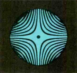
Fig. 1-Holograms can reveal microscopic problems, but without depth or direction.
In the 1970s, the development of holography made possible a new kind of analysis. A hologram can be considered as a three-dimensional measurement made by bouncing phase-coherent light off a moving or three-dimensional object and then comparing or interfering it (hence interferometry) with a reference beam that is also phase-coherent. The technique creates a "beat" frequency which is transposed onto film or another two-dimensional recording medium to produce a hologram.
Holograms provided the first glimpses of speaker behavior on a microscopic level, but they pose some frustrating limitations. They can be used only with small speaker diaphragms and displacements. Another drawback is that holography is analogous to contour map illustrations. As Fig. 1 shows, you can see where the problems occur only via line intensity or thickness. The burden of determining where the problems occur on the diaphragm itself and the level of displacement, was left to the engineer and his imagination.
Furthermore, holograms are at best blurry and indistinct. Worse, they are only two dimensional, and it is impossible to see whether the vibrations are moving up or down. Using a laser and a specially programmed computer, a group of researchers at Celestion have created a system that shows speaker vibrations in animated form, clearly and unambiguously.
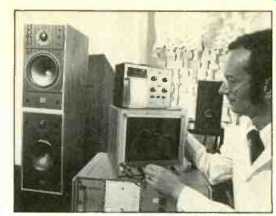
above: Celestion engineer Gordon Hathaway
also uses conventional amplitude
response plots to supplement the
animated computer plots.
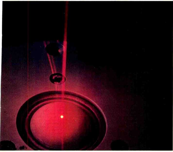
The laser-computer system operates in three steps. First, at the command of our computer, a neon-helium laser scans the surface of a vibrating speaker diaphragm, gathering information on diaphragm motion at more than 32,000 points. The computer instructs the laser how to scan, either straight across or in an arc, and at any frequency in the audio range, from 20 Hz to above 100 kHz. Second, a phase sensitive detector gathers the data and relays it into the computer, where it is processed and fed to an X/Y plotter. Third, the plotter draws a three-dimensional picture of the diaphragm movement as it appeared at the instant of the laser scan. Successive plots are stored in the computer and can be displayed later on an oscilloscope as a three-dimensional diagram, providing a clear indication of the direction of surface waves moment to moment.
At first glance, a single frame from the animated plot might resemble a topographical map of a bizarre, far-off planet. Actually, what one sees is speaker diaphragm displacement or velocity, magnified thousands of times and frozen in time. It is as if you were able to shrink yourself to about a fifth of a millimeter in height, and hover a bit above and to the side of an operating loudspeaker.
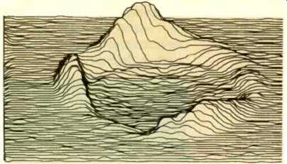
Fig. 2A--At 8kHz, this
19mm plastic-dome
tweeter shows severe
asymmetric surround
resonance.
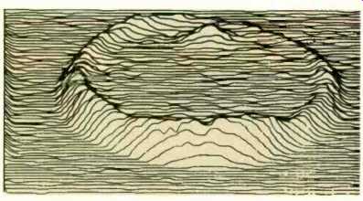
Fig. 2B--Ultra hard metal dome shows asymmetric decoupling of its surround
at 8kHz.
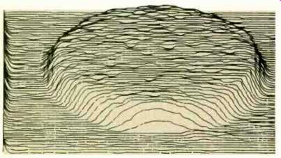
Fig. 2C--Copper alloy treble unit at 8 kHz is correctly controlled, nearly
a perfect piston.
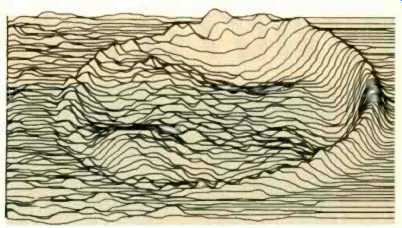
Fig. 3--At 780 Hz., this conventional bass/midrange unit shows four irregular
bell modes and an asymmetric surround problem.
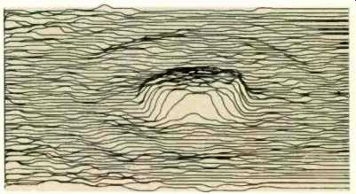
Fig. 4--A severe dust dome problem shows up in the bass/mid unit at 1.3 kHz.
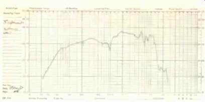
Fig. 5A--In the amplitude response curve of a 5-in., kHz. paper-cone midrange
unit a sharp dip occurs at 1
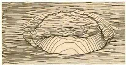
Fig. 5B--At 1022 Hz, laser-computer animation reveals a rocking mode, caused
by the mass of the lead-in wires.
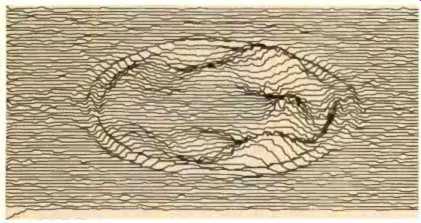
Fig. 5C--A high resolution plot at 2.4 kHz shows the lead-in wires' "leash" effect
even more dramatically.
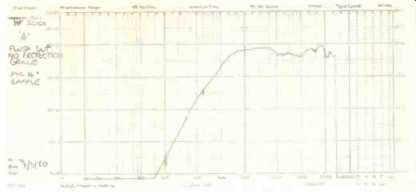
Fig. 6A--Sharp 14and 21-kHz dips mark amplitude response of a Mylar tweeter,
which is relatively flat from 1.1 to 28 kHz.
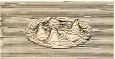
Fig. 6B--A high resolution plot at 14,274 Hz shows a severe, four pole bell
mode.
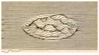
Fig. 6C--At 21,031 Hz, the bell mode is eighth-order, but with less effect
than the 14,274-Hz mode.
Rendered graphically in this fashion, speaker vibrations begin to make a great deal of sense. And speaker misbehavior becomes apparent even to untrained eyes. Good sound-that is, sound born of perfectly formed vibrations-is produced when the diaphragm rises up in the form of a broad, flattened piston. Depending on the frequency, the surrounding area will either be flat and unmarked or ringed with a circular, moat-like indentation. Departures from this ideal "topography" represent varying degrees of sound distortion.
Examining both test speakers and actual, marketed models, our engineers believe they can confirm much of what had long been theorized about speaker vibrations. More interestingly, they've found that many of the problems existing in speakers, their own as well as competitive brands, arise from design features that have been conventions of moving-coil speakers for decades.
One of the areas Celestion has researched is the materials speaker cones and domes are made of. New diaphragm materials like Bextrene, polypropylene and Mylar are a feature of each new generation of loudspeakers. But now there are concrete, quantifiable means of judging their performance.
Consider for example the laser computer plots in Figure 2. The first, Fig. 2A, shows a 19mm plastic dome tweeter at 8 kHz, with a severe asymmetric surround problem, distorting the sound well within the audible range. The second, Fig. 2B, shows an ultra-hard dome tweeter whose diaphragm is behaving; but this unit also has a surround problem. Its smooth, piston-like response is conclusive proof that the new, harder material is able to withstand higher frequencies without distortion. But as with most conventional drive units, surrounds and suspensions can lead to many mechanical problems-few of which are evident on amplitude response curves. The third plot, Fig. 2C, is a new copper alloy tweeter with no major diaphragm or surround problems.
Configurations of drive units can also be scrutinized for distortion-producing flaws, and this is an area where the laser computer has far outdistanced other measurement techniques. The standard amplitude response curve has for many years enabled us to see the acoustic effect of one particular moment of speaker motion over a range of frequencies; or, by averaging amplitude responses at different angles from the speaker, to build a polar curve at one frequency.
What it takes for granted is that what we see at one moment of measurement is true over time. In fact, this is not so. By using the laser computer to animate vibration modes, we have been able to see how energy moves through a drive unit over time, and lo understand the dynamic relationship of the speaker's parts.
For example, a critical problem to solve is how a woofer cone can be terminated by its surround so that energy which is not propagated into the air as sound (but travels sideways into the cone instead) can be stopped dead by the time it reaches the woofer basket. As the woofer is driven at higher and higher frequencies, a smaller portion of its surface is occupied with delivering the source sound, and the edges of the cone are left behind to "ripple" as energy flows rapidly outward from the center. Ideally, this energy is quickly slowed down by the surround and will decay completely by the time it reaches the edge of the basket. If the surround does not properly--and symmetrically--damp this energy, it radiates back into the cone, where it can be released-into the air in delayed fashion, coloring any new sound being generated in response to the drive signal. This phenomenon is known as a "standing wave," and it will continue going back and forth in the cone until all of the energy is eventually released.
As standing waves occur in the midrange, where the ear is most sensitive to sonic aberrations (and where vocals and the fundamental energy of most musical instruments are generated), it can be said to be responsible for a major coloration effect of loudspeakers.
To illustrate how the laser "sees" the woofer surround, we have shown in Fig. 3 a woofer driven at 780 Hz, having bell modes and a severe edge termination problem. At the moment illustrated, the energy is concentrated on the right-hand edge of the surround. With the computer in animation mode, we can see the cone rising first on one side, then the other, as this undamped energy "swishes" back and forth until it finally decays. Clearly, this surround is not properly damping the cone. A response curve of this phenomenon might show a slight peak or dip, depending upon the moment at which the measurement was recorded, but would not begin to illustrate the dynamics of the problem. Designing this problem away using conventional test techniques would be time-consuming, to say the least.
After considerable observation of such plots in animation, we have realized that a basic theme underlying speaker behavior problem is complexity: Too many parts, too many joints and boundaries, each vibrating more or less differently from the other and each more or less contributing to a whole that only approximates vibrations as they occur in live music.
Dust caps are notorious--and almost every woofer has one. They pin the cones at their outer diameter, absorb some of the sound radiating from the coil, and are likely to take off completely independently of their cones (see Fig. 4). This can be a real problem if the speaker has been basically designed and a "cosmetic" dust cap is put on later.
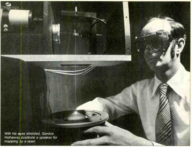
With his eyes shielded, Gordon Hathaway positions a speaker for mapping
by a laser.
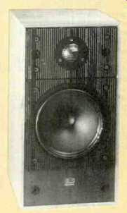
above: Celestion's SL-6 is the first system to use drivers designed with
the aid of laser-computer animations.
The laser computer has illuminated problems in many of the most accepted speaker assembly techniques, such as bringing the signal lead wires from the top of the voice coil through the diaphragm. A typical five-inch, paper-cone woofer of this type has been measured (Fig. 5A). Its amplitude response shows a sharp dip -5 to 8 dB across a narrow range centering at about 1 kHz. Seeking the culprit, we took some laser plots. At 1022 Hz, we discovered the severe rocking mode shown in Fig. 5B. In animation, this appeared as if the cone were tilting or rocking from side to side. With the computer in high-resolution mode, magnifying our view of velocity over 20,000 times, we pin-pointed at 2.4 kHz the "tether" or "leash" effect of the lead-out wires, slowing the cone's velocity. The leads' additional mass, unevenly applied to the vibrating cone, caused the rocking mode. Such a problem will not only limit the speaker's overall output, but will create lobes in the polar response until the energy is "sucked out" at the sides. Proponents of this lead-out wire configuration have often found it necessary to apply eyelets or other damping material where the wires come through the diaphragm. Such devices can only compound the problem of unequal mass.
Sometimes problems of complexity show up on amplitude response curves, and sometimes they don't. A subtle example of this not-so-subtle challenge in speaker design shows up when'/ we measure a relatively good, 3-inch Mylar dome tweeter. The response curve would lead us to judge this tweeter a very good one (Fig. 6). It's within ±4 dB from 1100 Hz to 28 kHz with only a slight dip, on the order of 1 1/2 dB, at 21 kHz. A closer look at the "wobble" area under the laser, however (Fig. 6B), reveals a severe, four-pole bell mode at 14,274 Hz. With a high-resolution plot (Fig. 6C), we can trace the eighth-order bell mode to 21,031 Hz. While it is more evident on the response curve, this eighth-order mode is less critical to speaker performance in its redistribution of energy than the 14-kHz wobble, which was minimized in the response curve.
The cause in this case is a resonance set up in the glue joint between voice-coil former and diaphragm. The Nomex former is folded at that point, and the wrinkles at the fold put localized stress on the diaphragm assembly, transmitted through the glue joint.
Once again, the joining of unequal materials at a critical stress point caused a problem, visible primarily with the laser, a problem which will limit both performance and reliability of this otherwise fine tweeter.
The task facing us, now that our ability to understand speakers has taken a step forward, is to find ways of making speakers vibrate simply, purely and, most of all, more faithfully to the original sound. The ideal loudspeaker system is still far in the future; but we believe it will incorporate drive units whose vibration modes are well-controlled. Such a system will not require elaborate crossover circuits to correct the drivers, since two wrongs do not make a right-not even in physics. We have seen, in the lab, woofers whose uncontrolled resonances may be equalized out, only to reappear if they are mechanically excited by the tweeter.
These are just some of the aspects of speaker design that Celestion has been able to investigate with lasers. As an analytical tool, it paves the way for further improvements and a whole new generation of loudspeakers.
(Source: Audio magazine, Sept. 1982)
Also see:
Link | --Celestion SL-600 Loudspeaker (Feb. 1985)
Celestion UL-10 Loudspeaker (Jan. 1977)
= = = =