M. J. Salvati
THIS ARTICLE details the construction and operation of a battery-powered audio oscillator (see Fig. 1). The output of this oscillator is a low-distortion sine wave at each of six switch-selected frequencies. Full specifications are given in Table 1. This oscillator will be useful to the engineer, the serviceman, and the hobbyist. Typical applications include checking frequency response, sensitivity, speaker phasing, will not be particularly difficult for the advanced construction enthusiast, the beginner should be warned that an oscilloscope and a.c. voltmeter are required for adjustment, some parts will not be very easy to obtain, and several sources may have to be checked. Actual construction should not be very tough, however.)
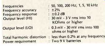
Table 1--Specifications
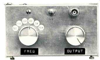
Fig. 1--Top of oscillator. Author's prototype uses BNC output jack instead
of phono jack.
Theory of Operation
The circuit is essentially a Wein-bridge oscillator with an FET controlling the gain of the circuit. Output signal appearing at pin 6 of IC1 is rectified by diode D1 to produce a negative d.c. voltage across resistor R14. This voltage is well filtered by capacitor C4 (and sometimes C5 or C6) and applied to the gate of FET Q1. The channel resistance of the FET forms part of the resistive feedback divider (R7 and R8) from the op amp's output to its inverting input. The FET can therefore adjust the feedback divider to maintain oscillation at a non-distorting level according to the magnitude of the rectified feedback voltage. This action also keeps the output amplitude relatively constant from one frequency to another despite differences in the match between resistor pairs R1 R6. For instance, if the output amplitude starts to get too high, the negative d.c. voltage at the gate of Q1 increases.
This increases the channel resistance of the FET, thereby increasing the total resistance from pin 2 of IC1 to ground.
This decreases the gain of IC1 and reduces its output amplitude.
The low circuit distortion is due to the FET's channel resistance being only a small portion of the total resistance from pin 2 to ground. However, the changes in channel resistance produced by the a.g.c. voltage at Q1's gate are big enough to perform the control function.
Another factor involved in achieving low distortion is adequately filtering the rectified output voltage used to control Q1. The time constant of resistor R14 and its parallel capacitor(s) must be very long compared to the period of oscillation. Capacitor C4 is adequate for the higher frequencies, but additional capacitance (C5 or C6) must be added for the lower frequencies. Large capacitance is not used at the higher frequencies to avoid unnecessarily long settling times.
The frequency of oscillation is determined by capacitor pair C1 and resistor pairs R1 R6, according to the standard Wein bridge formula:
f= 1 6.28 RC
Only one set of precision capacitors is needed because the input bias current of the N5556 op amp is so low that several decades of resistance can be used to produce the several decade frequency span.
IC 2 is connected as a unity-gain buffer that acts as an output driver for low-impedance loads. Resistor R12 builds up the output impedance of the device to near the 600-ohm impedance standard. Resistor R13 and switch S3 provide a "quick-and-dirty" method of achieving 40 dB attenuation of the output signal. If it is important to maintain 600-ohms output impedance at all output levels, the attenuator described in Modifications can be used instead.
Construction Notes
As far as layout is concerned, nothing is especially critical.
The general arrangement of parts shown in Fig. 3 yields an easy-to-wire device. The only caution is to be sure your circuit board will fit into the space available in the case. If you have little experience with miniaturization, build the circuit board first and then see how big an aluminum case is needed. Further details on the circuit board are given below.
Sources recently listing IC1, IC2, and Q1 include Ancrona Corp., P.O. Box 2208A, Culver City, Calif. 90230; James, P.O. Box 822A, Belmont, Calif. 94002; New-Tone Electronics, P.O. Box 1738AM, Bloomfield, N.J. 07003, and Solid State Systems, P.O. Box 617A, Columbia, Mo. 65201.
Circuit Board
The components covered in tone on the schematic diagram are to be mounted on the circuit board.
Use No. 22 solid wire to make the connections from circuit board to chassis-mounted parts; the short stiff wire leads make the circuit board self supporting.
Perforated board or printed circuit techniques can be used for the circuit board, although I recommend Veroboard by Vero Electronics. The metallized grid pattern accepts DIP IC's directly and permits incredibly-dense packaging.
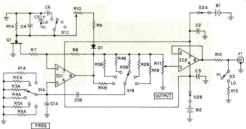
Fig. 2-Schematic diagram. Parts covered with tone are on circuit board.
FET For lowest distortion, Q1 should have a moderately high pinchoff voltage (around 3 volts). This is available from a 2N3819 type FET with an Idss of 8-10 mA.
Frequency-Determining Resistors
The absolute value of the frequency-determining resistors (pairs R1 R6) determines the frequency of oscillation along with the absolute value of capacitor pair C1. However, the relative value, or match between the two resistors of each pair, affects the circuits oscillatory activity, so each pair must be closely matched to produce the same output amplitude at each frequency. The closer the resistor pairs are matched, the less demand there is on the a.g.c. circuit to maintain output flatness. This allows the circuit to be optimized for low distortion.
The match between the resistor pairs can be achieved either of two ways. One is easy but expensive, the other is harder but cheap. First, you can purchase 1% tolerance resistors of the values specified in the Parts List. Second, you can measure a number of 5% tolerance resistors of the nearest standard value(s) and select from them the pair that are the closest match (and hopefully, near the specified value). A digital ohmmeter is recommended for this task, although a standard (analog) ohmmeter with mirrored scale can be used if you are especially good at meter reading. If frequency accuracy is important, a digital ohmmeter must be used.
If matches within 1% are not obtainable, or you are unlucky enough to buy 1% resistors that are off in opposite directions, always use the lowest-value resistor of the pair as the one connected to switch section S1A.
Feedback Resistors. The proper ratio between resistors R7 and R8 for low distortion and reliable operation is quite critical. The closeness of the match between capacitor pair C1 and resistor pairs R1 R6 affects the amplifier gain, hence the proper R7:R8 ratio. The values given in the Parts List for these resistors assume that parts of the specified tolerance are used for C1 and R1 R6. In this case no adjustment of R7 and R8 is needed. However, if poorly-matched components are used, resistor R7 should be a 22K 5% carbon resistor, and R8 should be replaced by a 43K 5 % carbon resistor (R8A) and a 5K trimmer pot (R8B), as shown in Fig. 4. Then, use the Feedback adjustment procedure in the next section.
Modifications. A simpler version of this oscillator covering only 200, 1000, and 5000 Hz can be built using 741's, or a 1458 or 747 for IC1 and IC2. In this case, omit capacitors C5 and C6, resistors R1, R2, and R6, and section C of switch S1. Use a 3-position, 2-pole switch instead for S1, and use a 0.47 capacitor for C4.
If a constant output-impedance step attenuator is desired, build the output circuit as shown in Fig. 5. Use a DPDT slide or toggle switch for S3 and 1/4-W carbon resistors of the values shown.
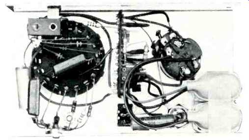
Fig. 3--Interior view. Circuit board is seen mounted edgewise between
FREQ switch at left at OUTPUT pot at right. Batteries are taped in place
at lower right corner of case.
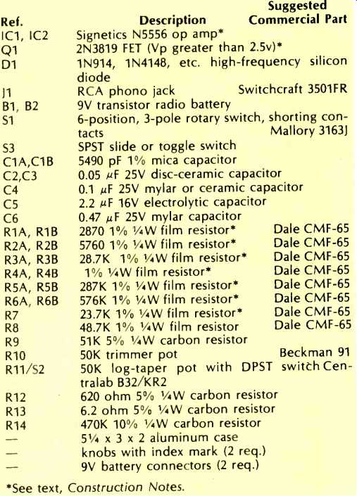
Table 2--Parts List
Adjustments
To adjust this audio oscillator, an oscilloscope and a.c. voltmeter are required.
If resistor R8 is a fixed precision resistor, perform only the Output Level adjustment. If resistor R8 is a combination of trim pot and fixed resistor, perform the Feedback adjustment and Output Level adjustment, in that order.
Feedback. To adjust the feedback, proceed as follows:
1. Set trim pot R8B for maximum resistance, and trim pot R10 at mid rotation.
2. Set the FREQ switch to 1 kHz and the output-level switch (S3) for HI output.
3. Connect an oscilloscope to the output jack (J1). Set the scope's input attenuator to 2 V per division.
4. Rotate the OUTPUT control fully clockwise, and observe the sine wave on the oscilloscope. Adjust trim pot R10 for a sine wave of about 8 V P-P.
5. Slowly turn trim pot R8B in the direction of minimum resistance while watching the scope. When you reach the point where the output amplitude drops below 4 V P-P or oscillation ceases entirely, turn the trim pot just enough in the other direction to produce a stable, constant-amplitude sine wave at all positions of the FREQ switch. (Note: the settling time is relatively long at 50 and 100 Hz; do not mistake this for instability.) When pot R8B is set towards the critical point (near minimum resistance), distortion is extremely low (less than 0.05%) but the output amplitude varies greatly from one frequency to another and the output voltage available is far below spec. Setting pot R8B in this area is recommended only for single-frequency operation and only if low distortion is far more important to the application than stability. Conversely, when pot R8B is set towards maximum resistance, distortion is relatively high (about 1%) but the output amplitude is extremely flat even with poor matches between resistor pairs R1 R6. Setting pot R8B in this area is recommended for applications where frequency response is more important than distortion. In between these extremes is an area where distortion and frequency response are both within the specification limits.
Output Level. Set the FREQ switch to 1 kHz and the output-level switch (S3) for HI output. Connect an a.c. voltmeter to the output jack (J1). Rotate the OUTPUT control fully clockwise. Adjust trim pot R10 for a voltmeter indication of 3 V RMS. As a final check, measure the output level at the other frequencies. If the difference between highest and lowest output amplitude exceeds 0.4 dB (or whatever you consider satisfactory), repeat the Feedback adjustment to determine the point that yields low distortion with low output-level variation. If a really-good distortion analyzer is available (Sound Technology 1700A or selected H-P 333A), check the distortion at 200 or 1000 Hz while performing these adjustments.
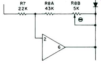
Fig. 4-Modification for achieving very low distortion.
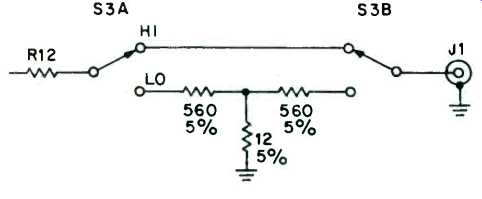
Fig. 5--Constant-impedance output attenuator.
Use
The various uses of an audio oscillator are too numerous and too well known to discuss here in any depth, so this discussion will be confined to applications where the special characteristics of this device are especially valuable.
The most unique feature of the oscillator, relative to commercial equipment in its performance class, is that it is battery operated. This permits use in systems where power-line ground loops cause feedback problems, in locations where access to an a.c. outlet is difficult, and in field servicing or adjusting portable (remote-pickup) equipment. Its small size is an additional asset when working in cramped quarters behind a console or equipment rack or when test equipment must be transported to a remote location. Although not exactly "vest pocket" sized, the oscillator can easily be packed in a toolbox or attaché case.
When the circuit is optimized for flat output, its frequency response will rival that of all but the very best oscillators on the market. Thus, it is suitable for critical frequency response measurements. Even if not so optimized, its frequency response is flat enough for nearly all studio measurements. Similarly, when the oscillator is optimized for low distortion, it can serve as the signal source for all but state-of-the-art distortion measurements.
(Audio magazine, Oct. 1975)
Also see:
= = = =