by JOSEPH GIOVANELLI
Connecting a TV set to a Home Music System
Q. How do I obtain audio output from my television receiver which can be fed to the auxiliary input of my music system?
-Charles Reibeling, Brooklyn, New York
A. Without having a schematic of your television set here as I write this, it is impossible to give you a concrete answer. All I can do here is give you some general guidelines to follow.
Many television receivers are of the series-heater-string variety, having no power transformer. If yours is one of these sets, do not attempt to connect it to your audio system without first obtaining an isolation transformer. Such a transformer is connected between the a.c. power line and the set. It does exactly what its name implies: it isolates the power line from the television set's ground system. The voltage appearing across the output socket of the transformer is the same as that supplied by the power line. The purpose of the transformer in this application is to ensure that the ground system of the set is not connected directly to the power line.
Without the transformer, the television set's ground system could either be at true ground potential or might be "hot" with respect to ground, depending upon the polarity of the wall plug. You can see that if the TV set's ground was actually "hot," and that if it is connected to a high fidelity system which is grounded, the full power line voltage would be shorted, blowing a fuse and possibly damaging the two pieces of equipment.
Further, we must not overlook the shock hazard which exists at the time that the connection is made.
Assuming that the set is a tube equipped unit, the signal can be taken directly across the volume control. However, if the set is of solid-state design, there will not be sufficient signal produced across this volume control to drive your high fidelity system. You should obtain your signal from the output of the stage following the volume control.
This means that the setting of the volume control on your TV set will affect the volume produced by your high fidelity system. This also means that the television set's internal speaker will also operate simultaneously with the high fidelity system. Its output can be silenced by simply inserting a single-pole single-throw switch in series with the speaker. If the set has a headphone jack, then a dummy plug can be inserted into it, cutting off the speaker. When sound from the high fidelity system is desired, the switch is open or the dummy is plugged in. This arrangement should be applicable to solid-state TV sets regardless of whether they use an output transformer or not.
In a tube-equipped set the amount of signal appearing across the volume control terminals is sufficient to drive the auxiliary high-level input of most home music systems. A further advantage is that the setting of volume control on the TV set will have no effect on the level of sound produced by your high fidelity system. Therefore, no switching arrangement need be provided to mute the television set's loudspeaker. Be sure that the ground side of the volume control is connected to the shield of the cable which interconnects the television set with the home music system. The "hot" side conductor of the cable is connected to the "hot" terminal of the control. The center lug is not used to provide any external connections.

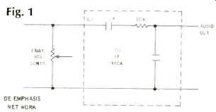
Fig. 1

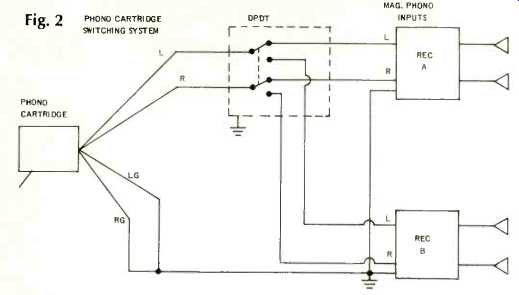
Fig. 2 PHONO CARTRIDGE SWITCHING SYSTEM

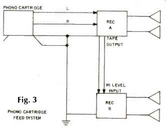
Fig. 3 PRONG CARTRIDGE FEED SYSTEM

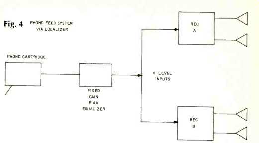
Fig. 4 PHONO FEED SYSTEM VIA EQ.
If there is an overabundance of highs, this means that the de-emphasis network in your TV set is located in some portion of the circuit after the volume control. Therefore, it must be added externally.
See Fig. 1. When using the TV set alone, use it in the manner to which you have become accustomed. However, if it is connected at all times to the high fidelity system, the input selector switch must be set to the proper input in order to prevent the audio of the TV set being shorted out. If this switch is set to the wrong position, nothing will be heard from the TV set's loudspeaker. When you wish to listen to the television program through the high fidelity system, the volume control of the TV set should be set to its minimum position so that no sound is produced by its built-in loudspeaker.
I have seen some instances in which the volume control of the TV set is used as the load for the detector. Under these circumstances, use a coupling capacitor connected between the "hot" side of the volume control and the cable feeding the high fidelity system.
Going back to transistor sets, the de emphasis network will probably be located at a point prior to the place where you are extracting output. If, however, the network is placed between this point and the following stage, you should connect your music system to the output side of this network.
You will almost certainly require a coupling capacitor between the output and your music system.
To facilitate a quick disconnect from the music system, an appropriate jack should be mounted on the rear apron of the chassis. Thus, interconnecting the TV set and the music system will simply be a matter of running a cable between the jack on the TV set and the appropriate input connector on the music system.
Impedance and Speaker Efficiency
Q. From reading several articles concerning amplifier power and speaker power requirements, I am under the impression that 8-ohm speaker systems tend to be more efficient than four-ohm speaker systems. Does speaker impedance per se have much to do with efficiency?
-John J. Serocki, Whitestone, N.Y.
A. There is no way to equate speaker efficiency with speaker impedance. Efficiency depends on magnet design, cabinet design, cone mass, and other parameters.
As you know, transistor amplifiers are designed to produce maximum power at some specified impedance. If the speaker's impedance is higher than this value, the amplifier cannot supply it with as much power as would be true if the speaker had an impedance equal to that which enables the amplifier to deliver its maximum rated power. This might lead you to think that speakers with, say, 16 ohms impedance are not as efficient as others of 8 ohms. However, this is really a matter of amplifier performance.
Connecting a Pickup to Two Receivers
Q. I would like to connect my phonograph to two separate receivers by means of two Y connectors. Would this be all right or would it cause an interaction between the two receivers?
-Frank L. Moore; Ogden, Utah
A. I do not suggest that you connect your phonograph to two receivers, at least not in the way you have described.
There are at least four reasons why I say this.
1. The shielded cable required to interconnect the two receivers to your phonograph system will be, obviously, of greater total length than that which would have been required to connect the phonograph to a single receiver. Added length means added capacitance, which, in turn, can result in some loss of high frequencies.
2. The combined load presented to the cartridge by the two receivers will be 23.5 K ohms. Most cartridges require 47 K-ohms for proper operation. Additional high-frequency losses are likely to result.
3. If you desire to use receiver A to hear a phonograph record, but receiver B is switched to some source other than phonograph, it is possible that the cartridge will be shorted out, rendering it inoperative as far as receiver A is concerned. As you know, selector switches often short out all unused inputs. Therefore, receiver A could not be fed from the cartridge except when both are switched to the "phono" position.
4. The common ground lead between the two receivers and the phono cartridge is likely to serve as a ground loop and introduce considerable hum into one or both receivers.
This hookup is better accomplished with a switching arrangement. See Fig. 2. Of course, this arrangement will not enable both receivers to obtain signal from the cartridge at the same time. If this is a requirement, another method must be devised.
One solution might be to connect receiver A directly to the phonograph pickup. Then connect the "tape out" jack of receiver A to one of the high-level inputs of receiver B. Thus, when playing a phonograph record, receiver A is switched to its "phono" position, and receiver B is switched to the position corresponding to the high-level input fed by receiver A. See block diagram of Fig. 3.
Solid-state equalizers are on the market; they have neither volume nor tone controls, but they do provide sufficient gain and equalization so that their input can be fed into the high-level input of an audio system, and they provide sufficient signal strength as well as the RIAA compensation. The phonograph cartridge could feed two receivers simultaneously by being connected as shown in Fig. 4.
This scheme has the advantage that the leads connecting the equalizer to the receivers can be rather long without producing significant loss of high frequencies. (I am assuming, of course, that the output impedance of the equalizer is rather low, as would be the case if an emitter follower stage is provided in the output of the equalizer.) This arrangement has the disadvantage that, if the receivers are to be used for separate functions, the phonograph circuitry will be shorted by the input selector switch, as was described earlier.
(Audio magazine, Nov. 1970)
= = = =