
by LEONARD FELDMAN
OF THE MANY MILLIONS Of FM sets currently in use, relatively few are designed to take full advantage of all the benefits in performance inherent in wide-band FM transmission.
Those manufactured for use in high fidelity component systems constitute the exception, rather than the rule. Less expensive "table models," portables, and other "combination" sets often sound no better than an equivalent garden variety AM radio. Their fault lies primarily in two areas. They have poor limiting characteristics and their ultimate signal-to-noise ratio is so low as to limit the useful dynamic range of listenable program material. Poor limiting results in great variations of audio output level as you tune from weaker to stronger signals, necessitating constant readjustment of the volume control. In extreme cases, with very weak signal input to the antenna, the volume control has to be turned so high that receiver-generated hum and noise make the program all but useless.
Since full limiting often requires an input signal of as high as 1000 microvolts or more (a level of signal obtained only from the very strongest stations with an outdoor antenna in use), most stations are heard with varying amounts of background noise, especially noticeable during quiet passages of music or speech.
Of course, if one wants to re-build such sets internally, from front end through i.f. strip, performance could be improved, but few experimenters are "hardy" enough to rip out the innards of a tightly wired, p.c.-board-constructed compact FM radio. Instead, we propose to offer an interesting solution which, in nearly every case tested, can actually turn your FM set into. a high fidelity component without your having to alter the circuitry of your set at all. In fact, in about 60 per cent of the cases with which we tested our FM-i.f. "Probe," we didn't even have to get inside the cabinet of the FM radio involved!
What is The FM I.F. "Probe"?
Nearly every FM set in use today consists of an r.f. front end ( the section which tunes to the desired frequency of the incoming signal, amplifies that signal and converts it, by super-heterodyning, to a fixed frequency of 10.7 MHz) and an i.f. strip ( which amplifies the 10.7 MHz signal and demodulates the audio information by means of a ratio-detector or a discriminator). Even the poorest combination of these elements results in an enormous amount of amplification, so that in the physical vicinity of the FM detector, large amounts of 10.7-MHz signal are present-often measured in significant fractions of a volt or even in volts. What's more, the high-frequency voltage present near the detector has a tendency to "radiate" over fairly small distances, much like a small transmitter, tuned to 10.7 MHz. The FM i.f. Probe which we constructed consists of a pickup coil, tuned to resonance at 10.7 MHz.
The output voltage of this coil is fed, by means of a short length of shielded cable, to a multistage 10.7-MHz i.f. circuit, featuring two tuned IC i.f. stages followed by a combination amplifier limiter-quadrature detector IC which incorporates the equivalent of 19 transistors, 6 diodes, and 18 resistors! This i.f. strip actually reaches full limiting when fed with an input of as little as 10 microvolts of 10.7 MHz. By way of comparison, most FM sets on the market today require considerably more signal to reach full limiting and, don't forget, we're talking about an i.f. signal only, whereas complete sets include the gain of the front end as well and still fall short of this limiting specification. Bandwidth of the i.f. circuit we built is just over 350 kHz, and the detection characteristic is extremely linear.
Total harmonic distortion at all signal levels from 20 microvolts to 100,000 microvolts was measured at just over 0.25 per cent for full ±75-kHz deviation and the components were chosen to make alignment simple and foolproof.
In actual use, the "probe" coil ( shown pictorially in Fig. 1) is placed in the vicinity of your FM radio's i.f. strip--preferably near the detector. The deemphasized audio output of the outboard i.f. strip (pictured in Fig. 1) may be fed to the high-level input of any good-quality audio amplifier and loudspeaker combination. As you tune your old FM radio across the band, you will hear the various stations coming through-as if by magic!
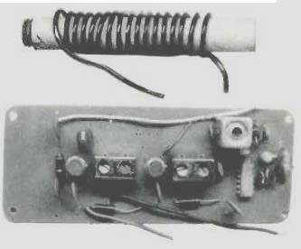
Fig. 1--Showing pickup coil and completed i.f. board.
Optimum placement of the "probe" can then be determined on the basis of cleanest, noise-free reception. In the photo of Fig. 2, the author is shown using the "probe" with a popular all-band portable receiver which also featured an FM band of questionable merit. The 10.7-MHz "spray" from this set was sufficient to preclude having to go inside the set with the probe. Full limiting (and quieting S/N of better than 65 dB) was obtained with the probe held parallel to the back of the set at distances up to four inches from the housing!
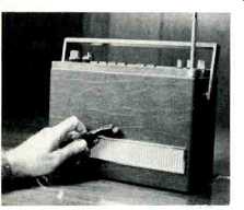
Fig. 2--Using the probe with a popular all-band portable.
I.F. Circuit Description
An overall circuit diagram of the i.f. strip is shown in Fig. 3. Input signal from the 10.7-MHz probe is fed to two cascaded µA703 E integrated circuits, each of which is terminated in an interstage dual-tuned i.f. transformer. Power gain of each of these stages is approximately 26 dB. A schematic diagram of the internal construction of the 703 device is shown in Fig. 4. The output of the second IC is fed to the Sprague Type ULN-2111A integrated circuit previously mentioned. A schematic of the contents of this remarkable IC is shown in Fig. 5. The amplifying groups of transistors to the left of terminal 10, in the diagram, comprise the amplifier-limiter section of the device and are capable of voltage gain of over 50 dB. The remaining pairs of transistors (to the right of terminal 10 in Fig. 5) constitute a quadrature-detector circuit. This highly efficient and linear form of FM detector operates in the following manner. The "direct" signal, as recovered from the amplifier section, is fed to one input of a "dual gate" circuit. The amplified signal is also applied to a phase-shifting network consisting of "C" and "L" and the coupling capacitor between pins 9 and 12 of the device. This combination presents a 10.7-MHz signal to the second element of the dual gate which is phase-shifted 90 deg. with respect to the primary or direct input. The duty cycle of the gate ( period during which both inputs are in the "on" or conducting state), with no audio modulation applied, is therefore 90 deg. Since the L/C combination is tuned to resonance, frequencies above and below 10.7 MHz will cause greater or lesser phase shifts and therefore greater or lesser pulse widths at pin 14 of the device. The capacitor at pin 14, labeled (DE-EMP.) serves to smooth out these pulses to a fluctuating d.c. level which follows the audio information waveform exactly. Normally, this capacitor can also serve as the deemphasizing capacitor required in FM reception, to provide the required 75-µsec. de-emphasis characteristic. In our design, however, we have used only 330 pF of capacitance at this point, to provide flat response beyond 60 kHz in the event that you want to use this device to feed a stereo multiplex decoder circuit. Actual de-emphasis for monophonic listening is accomplished externally, by means of R-5 and C-17 in Fig. 3. Should you desire to use the "probe" only for monophonic FM reception, C-15 may be changed to 0.01µF, and R-5 and C-17 may be eliminated entirely, with the audio output taken directly from pin 1 of the ULN-2111A IC.
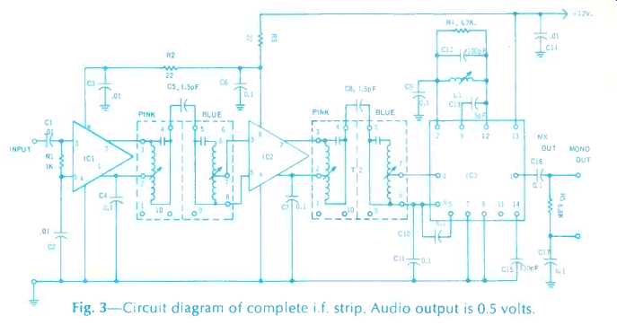
Fig. 3--Circuit diagram of complete i.f. strip. Audio output is 0.5 volts.
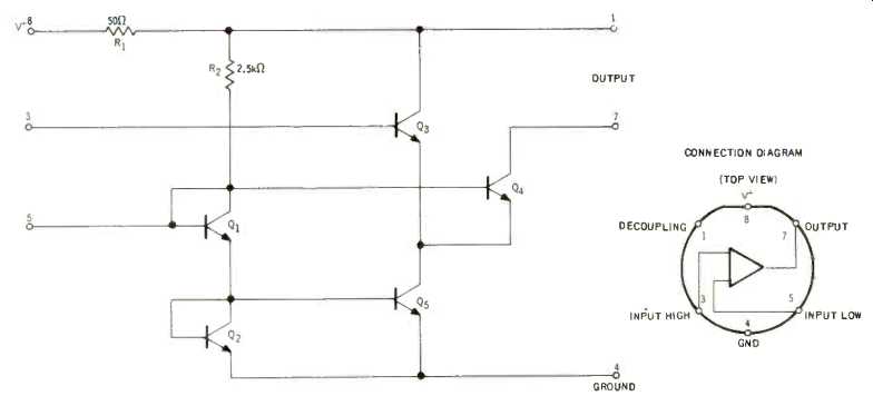
Fig. 4--Circuit and biasing arrangements of Fairchild µA 703 IC.
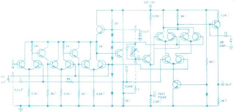
Fig. 5--All the above circuitry is contained in a single 14-pin 'inline'
IC, except items shown dotted, which must be added externally. "C" is
C-12 in figure 3, L is L-1 and the capacitor marked DE-EMP is C-15 in Figure
3.
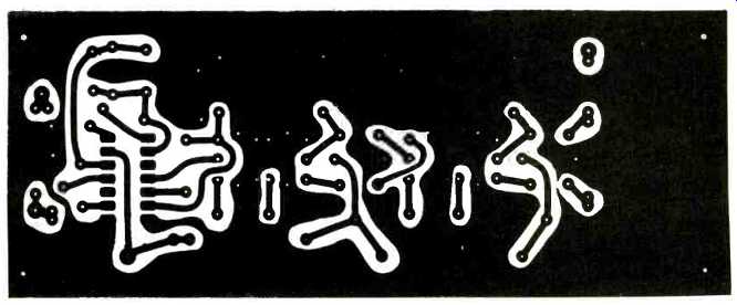
Fig. 6--An exact-size layout of the board. Copper side is uppermost.
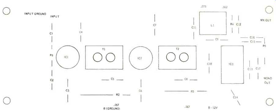
Fig. 7--Board viewed from the components side. Decimal dimensions refer
to oversized holes to be drilled. All other holes are drilled .040 to .050
in diameter.
Construction Tips
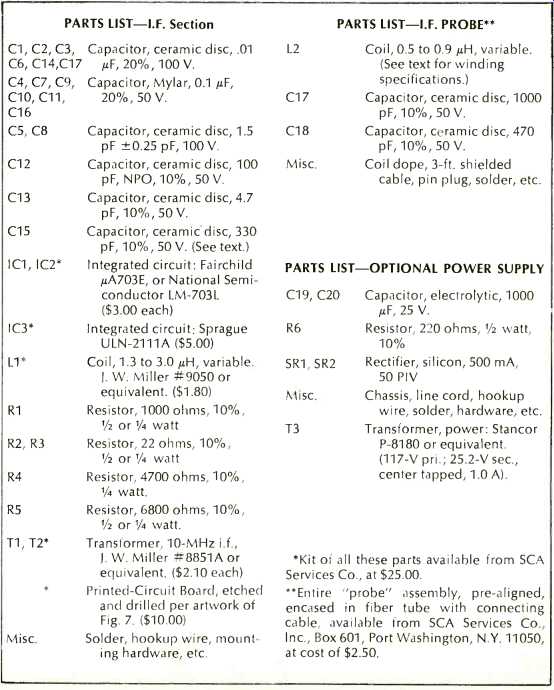
A complete parts list for the "probe" and i.f. sections is tabulated at the con elusion of this article. While all the parts are standard catalog items, some electronic distributors may not carry all of them in stock at all times. Certain specialized parts, such as the IC's, interstage transformers, and "quadrature coil" may be obtained by writing to SCA Services Co., Inc. P.O. Box 601, Port Washington, N.Y. 11050. An exact-size layout of the p.c. board is shown in Fig. 6. In this view, the copper side of the board is facing you.
In Fig. 7, parts positioning is indicated, this time looking from the insertion side of the board. Decimal notations next to coil and transformer mounting holes indicate hole sizes to be used. All non dimensioned holes may be drilled .040 to .050 in diameter. The four corner holes are for mounting the board to a suitable chassis or enclosure and should be drilled to clear the hardware you intend to use.
A pre-drilled, etched circuit board for use in this project is also available from SCA Services, for those who don't feel up to laying out and etching their own p.c. boards. When inserting the i.f. interstage transformers, be careful not to insert them backwards. When properly inserted, the pink tuning slug on each transformer will face towards the input end of the p.c.
board. Basing of the 703 IC's should also be observed carefully. If Fairchild µA703's are used, the fiat surface of the IC will face towards the following interstage transformer. In the case of National Semi Conductor devices, the keyway at the base of the device will face the following transformer. Note that pins 2 and 6 do not exist on this device, though it has the normal 8-pin numbering of a standard 8-pin housing for IC's. The ULN-2111A is a fourteen-pin, dual in-line IC, and care should be observed not to insert it backwards as well. Pin 1 is coded by means of a small circular depression on the top surface of the IC. In soldering the IC's in the circuit board, apply adequate heat for a short period of time, rather than lower heat for a lengthier period. A very small pencil-tip iron will prevent solder shorts between the closely spaced terminals of the 14-pin IC.
Constructing the Probe Coil
After much experimentation we found that 17 turns of #18 enamel-covered wire, wound on a 0.281 diameter nylon coil form, supplied with a powdered iron tuning core (J. W. Miller #4200-2) resonated perfectly with a 330-pF ceramic capacitor at 10.7 MHz. The turns are wound in a single layer over the full length of the coil form. The Q obtained with this arrangement was better than 110. Of course, if you have access to a simple paper-tube coil form of roughly the same dimensions, into which a powdered iron form about 1/4 in. long can be screwed, the results will be just the same. In order not to "load down" the resonant circuit by means of the relatively low input impedance of the i.f. circuit, impedance matching is accomplished by means of capacitor voltage division, as shown in the diagram of Fig. 8. The net capacitance of 1000 pF and 470 pF in series equals the required 330 pF for 10.7-MHz resonance, while the 1000-pF capacitor more closely matches the input impedance of the first i.f. stage. The addition of a short length of shielded cable across the 1000-pF capacitor, required to get from the probe to the i.f. board, does not affect overall capacitance sufficiently to prevent tuning the circuit to 10.7-MHz resonance. As an example, if three feet of cable is required ( greater lengths should not be attempted ), and the shielded wire or coaxial cable has a capacitance of, say 50 pF per foot, then the effective capacitance of the 1000 pF capacitor and its parallel cable capacitance will be 1150 pF. But this altered value of capacitance is still in series with the 470-pF capacitor, so that the net capacitance in the resonant circuit shifts only from about 320 pF up to slightly more than 340 pF. The tuning core can easily take care of these slight variations.
The end of the probe shielded cable can be connected directly to the input of the i.f. board. The shield should be soldered directly to the copper ground of the board, as close to C-1 as possible. If you would like to have the probe removable, the end of the cable can be equipped with a phono-tip pin plug and an appropriate jack can be incorporated in the i.f. board housing.
Alignment of the Probe
While the use of a signal generator capable of being sweep modulated will ensure perfect alignment of both the probe coil and the i.f. section, nearly perfect alignment of these elements can be accomplished using "off-the-air" (or, more properly, "off-the-radio") signals.
The completed i.f. board is powered by means of positive 12 volts, d.c. Since the entire unit draws approximately 30 milliamperes of current, the power supply need not be very elaborate. A 12-volt battery, such as Burgess type TW-2 will provide between 200 and 300 hours of service, if used intermittently for, say, 4 hours at a time. Alternatively, the simple power supply shown in Fig. 9 can be built, using parts tabulated in the parts list. The dropping resistor may need to be adjusted slightly in value, depending upon transformer and rectifier efficiency, but in our case it turned out to be 220 ohms. This provided exactly twelve volts of d.c., under operating load conditions.
Actually, the i.f. circuit will work at any voltage from about 10 to 14 volts, but gain will be somewhat reduced (as will audio recovery) when lower voltages are used.

Fig. 8--Diagram showing probe construction.

Fig. 9--Suggested power-supply circuit.
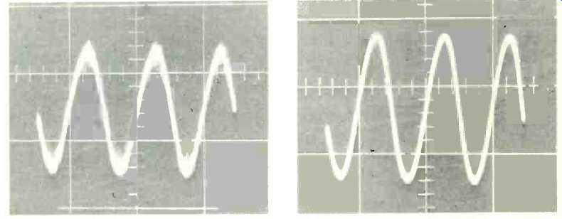
Fig. 10--Recovered audio signal with 20 µV of i.f. signal (10.7-MHz). Fig.
11-Recovered signal with 100 µV of 10.7-MHz signal applied.
If no generator is available, connect the output of the i.f. board (junction of R-5 and C-16) to the input of an audio amplifier: Connect the i.f. probe coil as previously described. Apply power to the i.f. board. You should hear a rushing, random noise. As you move the probe coil near the FM detector circuitry of your FM radio or tuner and start tuning in stations, some sound should be heard from your audio amplifier's speaker system. Move the probe until this sound is accompanied by the least amount of background, rushing noise. Chances are that the sound of program, though noise free, may still be garbled or distorted. Rotate the tuning slug of L-1 ( the "quadrature" detector coil) until the sound becomes clearest and least distorted. Next, move the probe coil away from the optimum physical location until noise just begins to re-appear. Care fully rotate each slug of the two inter stage transformers back and forth for reduced noise and clearest program. Rotation of these slugs will seldom be more than a half turn or so. Each time you clear up the sound and reduce the noise, move the probe a bit further away from your radio's detector area so that you once again hear noise coming through ( this is the same procedure you would follow in using a signal generator-as you align the set you keep reducing the input signal strength). Finally, when you have re trimmed all four slugs and the L-1 slug for best and clearest sound, tune the core of the probe-coil. In doing so, do not hold the coil with your fingers as this would upset the Q of the circuit. Tape down the coil in a fixed position and insert the proper tuning tool to rotate the core or slug. You should reach a definite peak in clarity of sound ( and reduction of noise) . Tuning this slug to either side of this optimum point will result in a degradation of the signal which is quite apparent audibly.
Those of you fortunate enough to have a 10.7-MHz signal source capable of sweep modulation can align the i.f. system and the probe using essentially the same techniques outlined, observing the sinusoidal output and, if desired, the usual "S" curve associated with i.f. alignment. Figure 10 shows a recovered sine wave with just 20 microvolts applied directly to the input of the i.f. system ( generator was connected to the same point to which the "probe" would normally connect). In Fig. 11 we see the recovered sine wave with 100 microvolts applied. With the probe properly positioned, you should be able to pick up "radiated" signals at least this strong, and so the resulting audio will be as noise free or better. Finally, in Fig. 12 is depicted the overall "S"-curve response of this system, with 100 microvolts applied. It should be noted that the sweep width from end to end of this photo (horizontally) is at least ±300 kHz, and, as you can see, well over 200 kHz of that sweep is absolutely "straight line."
The i.f. strip was found to be extremely stable and not subject to regeneration even when operated out of any metal enclosure, right out on the open bench-top.
As a result, some readers may want to use this strip by connecting it directly into a radio, in place of whatever inferior i.f. section might be present. In doing so, a good ground strap should be connected between the existing front end and the new i.f. strip and examination of the schematic of the particular front end used should be made, to ensure that a proper impedance match is possible between the two systems.
Just for fun, we mounted our system in a small speaker enclosure, complete with a small 1-watt audio amplifier and power supply and a small monitor speaker, as shown in Fig. 13. We did this, primarily, so that we could take the device around to various local dealers to determine whether it would "pick up" signals from all manner of FM radios on their display shelves. (It did!) Imagine their surprise, though, when we held the innocent looking "wand" or probe near the backs of their portable FM sets and asked them to tune the sets, with their volume controls turned all the way down. With no connection to any of the sets, they (and we) suddenly heard clear, noise-free FM which, even with this admittedly limited audio arrangement, sounded better than it did coming from the "signal donor" sets.
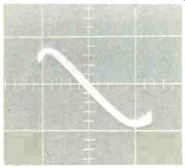
Fig. 12--Wide-band "S" curve of i.f. system shows extreme linearity.
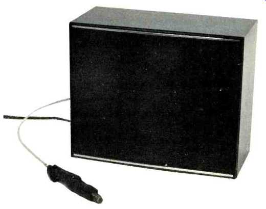
Fig. 13--Showing entire system mounted with amplifier, speaker and power
supply.
PARTS LIST
=============
(Audio magazine, Nov. 1970)
Also see:
How to evaluate FM stereo tuner performance (Jan. 1972)
How To Align Your Stereo Tuner (Part I)--Modifying the FM Generator (Jun. 1970)
"An Integrated Circuit FM Detector" (Feb. 1970)
Men of Hi-Fi--The Perfect FM Tuner (Jan. 1972)
New Specs for the New Tuners (Jan. 1973)
AM Stereo: An FCC Fiasco (July 1982)
FM Fidelity: Is The Promise Lost? (March 1985)
The Problem with FM (March 1985)
= = = =