MANUFACTURER'S SPECIFICATIONS: FM TUNER SECTION: IHF Sensitivity: 1.9 µV. S/N: 75 dB. THD: 0.5%. Frequency Response (Stereo): 20 Hz to 15 kHz within 1 dB. Capture Ratio: 1.8 dB. Selectivity: 75 dB. Spurious Response Rejection: 100 dB. Image Rejection: 90 dB. I.f. Rejection: 100 dB. IM Distortion: 0.5%. AM Suppression: 50 dB. AM TUNER SECTION: IHF Sensitivity: 150 µV/Meter. THD: 2.2%. Image Rejection: 75 dB. I.f. Rejection: 60 dB. S/N: 40 dB. AMPLIFIER SECTION: IHF Power Output: 110 watts, 8-ohm load @ less than 0.5% THD. RMS Power Output/Channel: 40 watts @ less than 0.5% THD. Power Bandwidth: 9 Hz to 30 kHz. Frequency Response: 20 Hz to 20,000 Hz ±1 dB. Damping Factor: 60. Hum and Noise: Magnetic Phono: (10 mV reference): 60 dB. Aux 1 & Aux 2: 70 dB. Input Sensitivity: Magnetic Phono: 3.8 mV; Aux 1 & Aux 2: 130 mV. Stability: Stable with all speaker loads. Input Impedance: Magnetic Phono: 47K ohms; Aux 1 & Aux 2: 150K ohms.
GENERAL SPECIFICATIONS:
Dimensions: 19" W x 6 1/2" H x 13 1/4" D.
Walnut cabinet enclosure included.
Price: $500.00
There's a "new" company to be reckoned with by the serious-minded high fidelity component receiver shopper these days. The quotation marks are there because, in truth, VM Corporation of Benton Harbor, Michigan has been in the electronics manufacturing business for just about as long as we can remember, but their previous efforts were directed more towards mass-produced popular-priced radio-phonographs and record-changers. With the introduction of two well-designed and excellent-performing receivers ( the Model TF-10/ Special differs from the TF-10/Deluxe only in power output, which is 80 watts IHF in the lower priced unit) VM has successfully made the transition to "our kind" of product design and production.
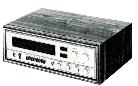
In terms of styling, VM was obviously in an advantageous position. Not bound by traditional concepts (and expensive previous model tooling which still had some economic usefulness), they were able to come up with one of the smartest looking front-panel designs it has been our pleasure to examine. The photo in Fig. 1 can hardly do it justice, nor can the verbal description which follows. Next to the recessed stereo phone jack at the lower left is a power on-off rocker switch which becomes uniformly illuminated when the switch is in the ON position. Further along the bottom of the gold colored panel is a series of eight push buttons. The two at the extreme ends of the bank are of the push-push variety and are used for FM muting and low-frequency filtering.
The others are inter-latched and are used for selecting FM, AM, Aux 1, Mic, Mag Phono, and Aux 2. A single microphone jack (also recessed) comes next (microphone use is limited to monophonic applications, regrettably), followed by four large control knobs. Three are dual acting, , in that the volume control, when pushed in, provides loudness contouring, the balance control, when pulled out, parallels both amplifier channels for monophonic operation and the treble control, when pulled out, introduces a high-frequency filter circuit. The bass control is located at the extreme right of the lower section of the panel-a reversal from usual practice which places bass to the left and treble to the right.
The large dial scale, normally blacked out in all but AM and FM functions, is brilliantly illuminated with FM frequency numerals only when the FM button is depressed and with equally dramatic AM frequency numerals when the AM button is pushed. There is no dial pointer, per se. Instead as you begin to tune from the low-frequency to the high-frequency ends of the AM or FM calibration, a brightly illuminated bar moves progressively along the scale.
Visibility of this scheme is so good that the tuned-to frequency is easily readable from across the room. This system of dial reading is reminiscent of speedometer indication used in Buick automobiles for several years, but as executed in the VM TF-10 receivers it is extremely effective, practical, and a delight to use. To the right of the dial scale area are two rectangular windows. The lower one illuminates in the FM mode to disclose an oversize center-of-channel tuning meter. The upper window becomes illuminated in the presence of a stereo FM signal. The other rotary control in the upper right section of the panel is a speaker selector switch which has positions for main, remote, or both sets, or with the speakers off.
The rear panel of the VM TF-10 receiver has the usual input jacks for low-level magnetic phono (2-millivolt nominal rating), high-level magnetic phono (7 millivolt nominal rating), AUX 2 and AUX 1 pairs, as well as a pair of RECORD OUT jacks. VM did not provide tape-monitor facilities on these receivers. FM (300 ohm) and AM antenna terminals are located directly over a ground binding post. Next come speaker binding posts which are of a high quality and designed to prevent accidental shorts between adjacent wires. However, we found the terminal posts clustered too close together and located in a position that makes it rather difficult to "get in" to effect the necessary connections. This condition is further aggravated by the fact that a single "common" post is provided for both the "main" and "remote" speakers of the left channel, and a similar arrangement is used for the right channel, making it necessary to wrap or insert two leads in each of these ground terminals if two sets of loudspeakers are used. The whole area is a bit cramped, but when one considers that these connections need be made only once, the problem is relatively minor. An a.c. convenience outlet comes next, followed by a fuse holder and a three-wire power cord ( the third wire intended to serve as a local FM antenna by capacitive coupling to the a.c. line). Internal Construction and Circuitry Figure 1 shows the top view of the receiver chassis. In addition to the sealed FM front-end, there are separate printed circuit modules for the AM and FM i.f. sections. The latter includes two integrated circuits as well as two phase linear 5-pole sealed toroidal filters which require no alignment. The FM front end includes four tuned circuits, two dual gate MOSFET's (for r.f. amplifier and mixer stages) and a bipolar transistor for the local oscillator. The multiplex decoder section utilizes a single multipurpose integrated circuit plus one stage of preamplification and isolation from the i.f. output. Tone-control circuitry is of the "losser" type, while the power amplifier sections are transformerless, employing a complementary-symmetry circuit which, with the aid of positive and negative 35-volt d.c. supplies, results in the elimination of any capacitive coupling to the loudspeaker circuits. Heat-sensing diode arrays affixed to the output transistors limit driver current when and if the output transistors start dissipating too much heat. These and the line fuse constitute the only forms of circuit protection incorporated in the receiver, aside from the very stable forms of bias regulation and zener-diode control of critical supply voltages. Mechanically, the layout is logical and easy to service and the chassis itself is rugged and well planned.
Heat sinks for the output transistors are more than adequate in size and no unusual heating problems were encountered during our extensive testing. The extra hole clusters visible at the top of Fig. 1 are used in the lower-powered TF-10/ Special receiver mentioned earlier for mounting less powerful output transistors directly to the chassis in that case. All r.f. and control facilities remain the same in the alternate receiver, however.
Performance Measurements
Beauty of external design is one thing, but when that excellence is accompanied by conservative specifications that are more than met in production units, a reviewer's job poses no conflicts at all.
To put it succinctly, the VM TF-10/ Deluxe Receiver met or exceeded every one of its published specifications and did very well by some of the specifications it failed to mention altogether.
Clearly, VM, intent upon conforming scrupulously to IHF required specifications, failed to include some of the more recent specifications that most manufacturers feel are important albeit they are omitted in the somewhat antiquated IHF standards for tuners and amplifiers.
Figure 2 is a plot of FM monophonic performance characteristics. Note that IHF sensitivity was measured at 1.8 µV, as opposed to the 1.9 µV claimed. More important, even, than the S/N of 75 dB achieved is the fact that S/N with a signal input of only 5 microvolts is already 57 dB, and 60 dB of S/N (the best figure obtained at any input with a great many receivers) is reached with a mere 7 µV of signal input-with still a ways to go for ultimate S/N of 75 dB which is reached with a signal input of only 50 µV. You couldn't ask for better quieting! Full (1 dB) limiting is reached at just about the same 1.8 µV as IHF sensitivity and THD decreases to 0.4% at any input signal greater than about 25 µV. While no "specs" are given for stereo FM separation, we plotted this characteristic in Fig. 3. Best separation of 35 dB was obtained at mid-frequencies and 30 dB of separation was maintained all the way down to 50 Hz with the high end decreasing gradually to 20 dB at 15 kHz. Next time, publish these figures, VM! They're nothing to be ashamed of.
THD and IM for the power amplifier section are plotted in Fig. 4. With both channels driven, we read 0.5% THD at 45 watts output as opposed to the 40 watts claimed. At rated output of 40 watts, THD was only 0.2%. At all power levels below 30 watts per channel, readings were below 0.05%. IM distortion reached 1.0% at an output of 45 watts per channel, decreasing gradually to under 0.1% at 1-watt listening levels and below.
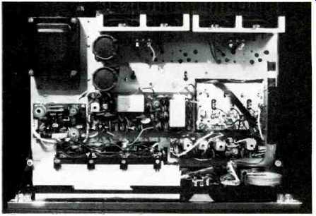
Fig. 1--Showing top view of VM receiver chassis.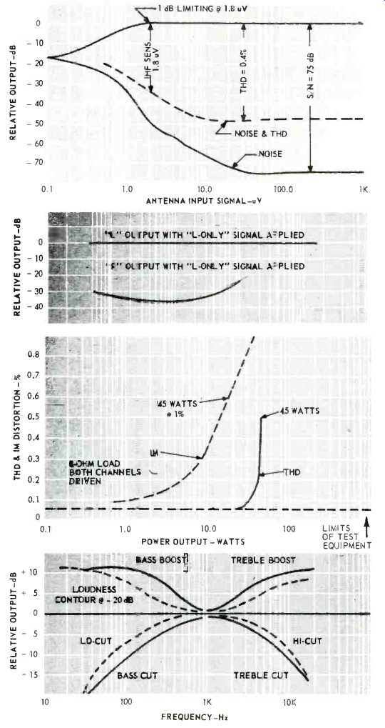
Fig. 2--FM monophonic performance.
Fig. 3--Stereo FM separation.
Fig. 4--Percentage of THD and IM distortion.
Fig. 5--Tone-control, loudness contour, and filter characteristics.
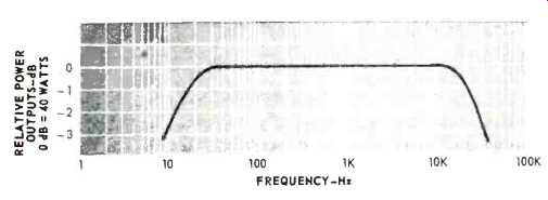
Fig. 6--Power bandwidth.
Figure 5 combines plots of tone-control range, loudness-contour action (at 20 dB below full volume setting), high- and low-filter characteristics, and frequency response. We felt that the low-cut filter begins to "bite into" the mid-range a bit too early while the high-cut filter is just about where we like to see it.
Power bandwidth is plotted in Fig. 6 and extends from 9 Hz (as claimed) to 32 kHz (a bit better than claimed) .
Listening Tests
In listening to the FM section of this receiver we were conscious of the excellent selectivity and overload characteristics of the design. We purposely used both indoor and outdoor antennas, to approximate all kinds of signal-strength situations. Of the fifty four stations received clearly with the high-gain outdoor antenna, only four were "disabled" when we depressed the "mute" control. Since the mute control threshold was measured as being at about 5µV, this suggests that the four stations previously heard (with mute out) were providing signal strengths at the antenna terminals of 5 µV or less. Re-tuning to these four stations, we found them, nevertheless, quiet and listenable. That's what you get when limiting takes place at less than 2 µV and when S/N rises as steeply as it does in the TF-10 receiver. The stereo indicator light, by the way, is absolutely positive. It's either oN or OFF-no flickering between stations.
AM reception was good, but not exceptional, and dial calibration for both AM and FM was extremely accurate from the low end to the high end of each respective band. In using the controls, we wish the loudness-contour and volume settings of the master volume controls were reversed. That is, we would have preferred to have to pull out the control to introduce loudness contouring, instead of the other way round, since, in our view, loudness contouring is a "sometime" use, whereas normal volume control action is more often desired, but a user would soon get used to this reversed relationship. As long as VM went to the trouble of creating such dramatic lighting for their AM and FM dial scale, it might have been nice if they had some visible ( illuminated) way of denoting Aux 1 & 2, Phono, etc. During the use of these facilities, the entire dial scale goes dark.
As for the power amplifiers, they provided good, clean sound to two sets of low-efficiency bookshelf speakers at dynamic levels which probably exceeded anything you'd want in your listening area and there was no evidence of "breaking up" at low frequencies. Transients were crisp, and there was no sign of any muddiness with a variety of specially selected recordings which we used.
The 60:1 damping factor, though not actually measured, certainly seems to be present. The sections of the master volume control tracked well, in that we did not require re-balancing by means of the balance control even at "whisper" levels.
While we have always been concerned with the completeness of customer instruction manuals, we learned a surprising lesson from VM's printed material which accompanies the TF-10 series of receivers. Instead of the usual "instruction manual," VM supplies just five single sheets of attractively printed information. The first sheet tells about installation ( speaker and antenna connections, etc.). The next sheet (printed on only one side, mind you) tells all you need to know about actually operating the receiver and should be used with the third sheet-a pictorial diagram of front panel and rear panel with numeral-coded explanations of all the controls, jacks, and so on. The fourth sheet ( again, printed one side only) tells about speaker selection considerations, while the final piece of literature, a single sheet folded in half to make a four-page brochure, lists features and specifications for the more technically oriented user to peruse at his convenience or leisure. A useful Technical Glossary is also provided, offering some ninety-one clearly expressed definitions of high fidelity terms. We tried out this "instruction sheet" approach with a couple of neophytes and, surprisingly, they were able to hook up the receiver and get it going in just a few minutes. Maybe the fresh thinking which VM applied to this excellent receiver extends to "instruction book" writing as well-and maybe VM, long experienced in producing merchandise for mass consumption can combine the best of both worlds as they enter the inner circle of componentry-for enter it they have-with the introduction of the TF-10 receivers.
-L. F.
- - - - -
(adapted from Audio magazine, Dec. 1970)
Also see:
= = = =