By Martin Clifford
TAKE AN ORDINARY inoffensive pedestrian, put him in the driver's seat of a sports car and you sometimes get a complete personality change. The pussycat becomes a tiger. Take an ordinary length of wire and loop it into a number of consecutive circular turns (Fig. 1) and you go from an ordinary current carrier to an electromagnet, a device whose varying magnetic field easily leaves its own confines and, busybody-like, tries to interfere with everything within its reach. Almost like removing the cork from a newly unearthed bottle only to find the thin wisp of smoke coalescing an evil genie.
With a difference, though. The magnetic field surrounding the turns of wire of a coil carrying current can be controlled.
And even more. The magnetic field can be harnessed, tamed, made to do useful work, even if that work results in the rasping sound of a cheap transistor pocket radio.
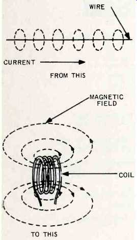
Fig. 1--The magnetic field surrounding a current-carrying wire becomes stronger
when the wire is wound in the shape of a coil.
Away From The Straight And Narrow
The Dr. Jekyll-Mr. Hyde transformation of a straight wire into a coil is a basically simple changeover, from straight to round. But round is capable of many ingenious engineering interpretations. A fundamental coil consists of circular turns of wire placed adjacent to each other, wound on some kind of supporting form (Fig. 2) made of wax or plastic impregnated paper, cardboard or plastic. Offhand, we might say there is nothing inside the form, but in this space age we are conscious of air, or its lack, and so this first coil is an air core type. A more complete name would be a single-layer air-core. And, to keep adjacent turns from shorting against each other, the wire is covered with an insulating material such as cotton, silk, nylon, rayon, glass or some plastic. Or else the wire can be insulated with a paint-like substance such as enamel or some special formulation described by an assigned trade name. If cotton insulation were used, the basic coil might now be identified as a single-cotton covered single-layer air-core type. This is still the same coil, but now the labeled accompaniment tells us a great deal more about its physical characteristics. As you can see, the electrical characteristics have been kept in abeyance.
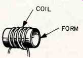
Fig. 2--The basic coil-turns of wire wound on a support called a form.
A single insulating layer, or single cotton covered, can be abbreviated as SCC. Add another layer and you have double cotton covered, or DCC. Cotton, silk, and nylon coverings, though, have been largely supplanted by plastic types.
Coil Types
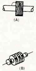
Fig. 3--Universal single pi (a) and triple pi (b) windings.
Successive turns of a single-layer wound coil can ultimately result in a component whose length is somewhat embarrassing and so a solution is to wind one layer on top of another. To keep the turns from falling apart, the coil can be sprayed with some plastic substance, varnish, lacquer or synthetic material or dipped in hot wax. But whether a single layer is used or many, the coil is sometimes called an inductor or solenoid or incorrectly referred to as an inductance.
During winding, the wire can be put down in a basket-weave pattern, a type of construction called a universal winding. A single winding, as shown in Fig. 3-a is a pi. It is possible, of course, to have more than a single pi, series connected as in Fig. 3-b. Other types of windings are variously called basket weave, spider web, etc.
Coil Names
Coils can also be identified by their electrical characteristics. A filter, as the name tries to suggest, separates currents of different frequencies. A choke, a somewhat more violent designation, does the same work. A tuned coil is one that is made to resonate at a particular frequency, comparable in a physical way to adjusting a violin string to a desired pitch. A voice coil is that part of a speaker responsible for moving the cone. These are just a few of the assigned jobs.
Inductance
An auto at rest likes to stay at rest, a condition many owners deplore. Similarly, a car in motion likes to stay in motion, a fact which led to the early invention of brakes. This stubborn behavior on the part of cars, or all other masses, is known as inertia. Coils have inertia, too, but of an electrical kind.
They oppose any change in the amount of current flowing through them, an electrical characteristic called inductance. The basic unit of inductance in the henry, with commonly used submultiples such as the millihenry, or thousandth of a henry, and the micro henry, or millionth of a henry. The amount of inductance of a coil is based on the way it is made: the number of turns, how wound, and the kind of material stuffed inside the coil form.
A large amount of inductance isn't necessarily better than a small quantity.
A locomotive has more inertia than an auto, but car owners will challenge its superiority as a mode of transportation.

Fig. 4--The inductance of a coil can be varied by moving a poly-iron core
in or out of the form on which the coil is wound.
Fixed And Variable Coils
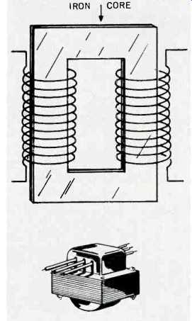
Fig. 5--Fixed iron core coil. The core consists of thin sheets of steel.
A coil can be fixed, that is, its inductance is a permanent feature and cannot be changed. Or, a coil can be variable and its inductance modified at will. This is ordinarily done by inserting a poly-iron slug (made of powdered iron and held together with a binder) into the coil form (Fig. 4). The presence of iron increases the inductance of the coil, and conversely, removing it lowers inductance, and so a variable coil can be made by having movable iron cores. Since a coil without a core is called an air-core type, one with a ferrous core material is an iron-core type. Iron-core types can be fixed or variable. Fixed coils (Fig. 5) often have thinly sliced sections of iron (laminations) as their core material.
Inductive Reactance
The inductance of a only factor involved in change of current. The coil isn't the opposing any frequency of the current flowing through the coil must also be considered. The frequency, in Hertz, multiplied by the inductance in Henrys, further multiplied by a constant, 6.28, supplies the current flow opposition known as inductive reactance, ordinarily abbreviated as XL. Inductive reactance, like resistance, is measured in ohms, a reasonable assumption since both reactance and resistance are implicated in current flow opposition. The vectorial combination of resistance and reactance, or total opposition to current flow, is called impedance, a word you will find in the spec sheets of just about all hifi manufacturers. The impedance of a voice coil of a speaker, for example, is a combination of reactance and resistance. The resistance of a coil is a fixed amount, depending directly on the wire used, its length, and the surrounding temperature. The reactance of a coil is frequency sensitive. The higher the frequency, the greater the reactance, a form of electrical behavior that is precisely opposite that of a capacitor. And so, voice coils have 4 ohms impedance, or 8 ohms, or 16 ohms, but only at a particular spot frequency. At some other frequency, the voice-coil impedance "is a whole 'nother story."
Coil Symbols
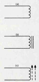
Fig. 6--Electronic symbols for coils. Air-core (a); fixed position iron core
(b) and variable poly-iron slug type (c).
As in the case of resistors and capacitors, electronic symbols are used for coils. The basic symbol for a coil (Fig. 6a) consists of a small succession of loops. In the absence of any further information, the symbol represents an air-core type. A pair of solid parallel lines (drawing b) adjacent to the coil indicates the coil has an unmovable, laminated-iron core. Fig. 6c is the symbol for a coil having a powdered iron core. The arrow means the core is adjustable.
The Magnetic Field
Every wire, no matter what its geometry, becomes a magnet when current flows through it, whether that current is d.c. or a.c. The wire becomes a magnet, not because it is made of copper, or some other material, but simply be cause the current is itself surrounded by a magnetic field or magnetic lines of flux or force. That same current, flowing through a vacuum, would still be accompanied by magnetic lines of force. With no current flowing through it, a coil simply becomes a series of circularly arranged wires. Because of this ephemeral behavior, coils are called temporary magnets or electromagnets (EM) in contrast to magnets which remain rather fixed and are called permanent magnets (PM). A speaker voice coil is an EM and is surrounded by a PM, and so the arrangement is called a PM speaker.
Magnets, like people, can be weak or strong. The stronger the current, that is, the greater the amount of current flow, the stronger will be the magnetic field around it. When a magnetic field is concentrated it perforce becomes stronger since there is more of it in a smaller space. And that's the great advantage of a coil over a straight length of wire-its ability to concentrate the magnetic field (Fig. 7).
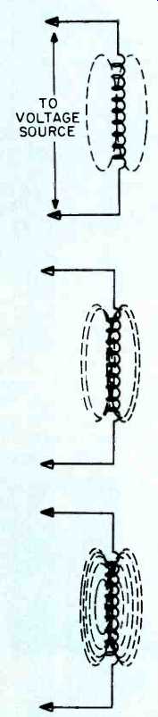
Fig. 7--The greater the current flow through the coil, the larger the magnetic
field around that coil.
Controlling Magnetic Fields
Magnetic fields are the Peck's Bad Boy of electronics. Uncontrolled, they can create havoc in the form of oscillation, quite capable of transforming a domesticated amplifier into a miniature generator. The various techniques used for taming magnetic fields are to keep coils widely separated, mounted at right angles to each other or, most commonly, a form of imprisonment known as shielding. In hi-fi systems, shields are not used to protect coils against inclement weather, but to ensure good behavior.
The Transformer
We have a transformer when two coils are placed within reasonable proximity of each other. The magnetic field of the first coil, identified as the primary winding or simply primary (Fig. 8), reaches across to the turns of wire in the second coil (or secondary). This has a very disturbing effect on the electrons resident in the turns of wire of this adjacent coil. It forces them out of their lethargy, compelling them to move to one end of the coil or the other.
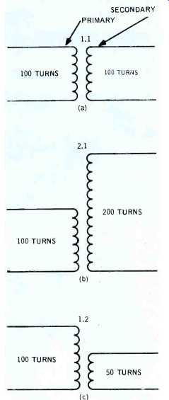
Fig. 8--A transformer may have the same number of turns for both secondary
and primary windings (a), have more turns on the secondary (b) or fewer turns
(c).
But this disequilibrium of electron quantity produces an electrical pressure, since there are now more electrons at one end of the coil than the other. This electrical pressure is actually the transfer of electrical energy through space, from the primary to the secondary winding, even if that space is measured in fractions of an inch. The electrical pressure across the secondary winding, produced by the magnetic field of the primary, is called an induced electromotive force or EMF.
Since a transformer consists of two or more coils sharing a common core, all of the previously named coil designations still apply. A transformer can be air core or iron core, and either fixed or variable.
Transformer Turns Ratio
A transformer can have the same number of primary and secondary turns and is then called a 1:1 (one-to-one unit). If the transformer has more secondary than primary turns, it is a step-up type, and if the secondary has fewer turns, it is a step-down type. The arithmetic ratio of the number of secondary turns to the number of primary turns is the turns ratio. A step-up transformer produces a voltage increase, that is, there is more voltage across the secondary than across the primary. There is a price to be paid, however. The current through the secondary becomes less than that through the primary. The stepdown transformer has more secondary current flow than the primary, but again at a price. The voltage across the secondary is less than that across the primary.
In the 1:1 transformer the secondary and primary voltages are identical.
Theoretically, the secondary current should be the same as that in the primary, but nature takes its toll. There are various losses due to heat and magnetization of the core material. Nature never supplies anything for nothing.
Would-be inventors of perpetual motion machines should realize this and take note that it isn't nice to fool Mother nature.
How To Read Simple Circuit Diagrams
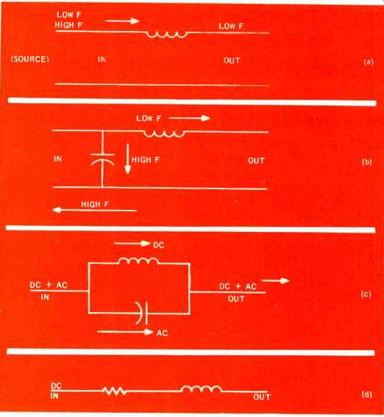
Fig. 9--Coils are used in conjunction with other components to form circuits
for doing specific jobs. Although coils are normally used in a.c. circuits,
drawing (d) shows a d.c. application to keep the direct current from reaching
an immediate maximum value.
Coils can form poly-connubial relationships with other components described in previous articles--with resistors, capacitors, tubes, transistors, and voltage sources such as batteries. The whole purpose of these arrangements is to help convert sound energy to its electrical equivalent, obtain a magnified replica, and then to reconvert to sound once again. But in so doing to have an amplified, completely faithful reproduction, a process known as high-fidelity.
In one of the simplest applications (Fig. 9-a) two widely separated frequencies (one frequency is much higher than the other), move along the conductor with the direction of movement indicated by the arrow. The lower frequency will go through the coil rather readily since the electrical opposition of the coil, its reactance, is smaller for low frequencies. The higher of the two frequencies will encounter much more opposition. This doesn't mean there will be complete separation between the two frequencies, simply that at the output there will be a much higher ratio of low-to-high frequency signal than existed at input.
Fig. 9-b shows a modification with a capacitor shunted across the connecting wires. Coils and capacitors behave in opposite ways. For a low frequency the capacitor has a high reactance, the coil a much lower one. And so the low frequency has every reason to continue through the coil toward the output. For this low frequency the capacitor offers very little encouragement as a possible current path. However, the higher frequency finds relatively easy passage through the capacitor, returning to the source.
A combination coil-capacitor circuit, similar to this one, is a filter, often used as a circuit arrangement for frequency separation, possibly at the input to a speaker system.
In some circuits it may be necessary to separate, momentarily, d.c. (actually a zero frequency current) from a.c. The d.c. and a.c., both moving along the same wire are separated by the coil connected across the capacitor (Fig. 9-c) referred to as a shunt circuit. The capacitor has its maximum opposition to d.c., and so the d.c. is compelled to move through the coil. For a.c., the coil will have a high reactance, the capacitor much lower, and so the a.c. will use the capacitor as a path. Naturally, some a.c. will also flow through the coil, but the separation can be made more complete by repeating the circuit.
In still another arrangement, a resistor is wired in series with the coil. The purpose here is not to stop the current from flowing but rather to delay it from reaching its peak value for a fraction of a second. The amount of time delay will depend on the value of inductance and resistance.
And So Into The Future
So much for components. There aren't many of them just resistors, capacitors, coils, tubes, transistors, and voltage sources. But with this handful we can now settle down to the serious business of understanding hi fi system components, starting with the tuner. Not now, of course. In the next issue.
( Audio magazine, Nov. 1972)
Also see:
The Language of HIGH FDELITY: Part II--Basic Electronic Components (Jun. 1972)
The Language of High Fidelity--Part VIII (Feb. 1973)
Language of High Fidelity--Part XI (May 1974)
= = = =