Manufacturer's Specifications:
Rated Output Voltage: 1 .0 V rms.
Maximum Output Voltage: 7.0 V rms.
Gain: Phono, 40 dB at 1 kHz; high level, 0 or 20 dB, selectable.
Frequency Response: Phono, RIAA ±0.25 dB; high level, 20 Hz to 20 kHz ± 0.25 dB, 10 Hz to 100 kHz-3 dB.
S/N Ratio: Phono, 88 dBV; AUX or line, 90 dBV; minimum volume, 95 dBV.
THD or IM: 0.005 percent, rated to maximum output, line or phono.
Phono Input Impedance: 47 kilohms and 200 pF.
Phono Input Sensitivity: 5 mV rms.
Phono Input Overload: 120 mV, 1 kHz, peak.
High Level Input Sensitivity: 50 mV rms.
Low Filter Response: -3 dB at 19 Hz, -29 dB at 5 Hz; phono only.
Crosstalk: High level to phono, 80 dBV.
Headphone Power: 150 mW.
Slew Rate: 7 V/µS.
Output Impedance: 600 ohms.
Dimensions: 19 in. (48.3 cm) W x 6 1/2 in. (16.5 cm) D x 1 3/4 in. (4.4 cm) H.
Weight: 5 lbs. (2.3 kg).
Price: $350.00, rack mount optional.
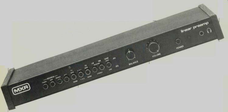
The Model 139 Linear Preamp from MXR is one of two relatively recent preamp additions to that company's line.
Unlike MXR's System Preamp, which was designed for mixing and complex signal routing, the Linear Preamp was designed for basic, simple control of audio signals within a high-quality stereo system. The low-profile front panel of this component is equipped with only a few needed controls. Three push buttons select tuner, AUX or phono inputs.
Three more buttons handle the two tape-monitor loops, including dubbing from one deck to the other in either direction.
Two additional buttons select combinations of mono or stereo reproduction, while a final button alters high-level gain from 0 dB (unity gain) to 20 dB, depending upon program source and power amplifier requirements. The manufacturer recommends that the gain switch be left in the 0-dB position for best signal-to-noise results unless special program sources or listening conditions necessitate additional gain.
Balance and volume controls utilize rotary knobs. To the right of these are a power on/off switch, a power indicator light, and a stereo headphone jack. Solid walnut end pieces enhance the appearance of the all-black component, and all nomenclature on the front and rear panels is in highly legible white screening.
The rear panel is equipped with a convenience a.c. outlet (North American version only), a pair of output jacks, the required input jacks plus tape out and in jacks for the two tape monitor loops, and a chassis grounding terminal adjacent to the phono inputs.
Circuit Construction and Highlights Virtually all of the audio signal circuitry of the Model 139 Linear Preamp is constructed on a double-sided military grade, glass epoxy p.c. board. The block diagram of Fig. 1 shows how each stage of the preamp is interconnected.
The phono section provides 40 dB of gain (at 1 kHz) with extremely low noise level. Resistive loading of the phono cartridge is factory set to 47 kilohms, while capacitive loading is set at 200 pF. Phono loading capacitors may be changed by the user if specific cartridge requirements dictate such a change, and access to these capacitors is relatively easy.
The subsonic filter is incorporated in the phono preamp stage to remove unwanted low-frequency information near its source. The filter is a three-pole Butterworth alignment type, with flat response in the pass band and a very sharp roll-off below 20 Hz (18 dB per octave). The. power supply, a potential source of hum in any low-level preamplifier, is extremely well filtered and decoupled from the phono preamp section in this design layout.
Muting circuitry in the Linear Preamp eliminates turn-on and turn-off transients. FETs, controlled by a time-delay circuit, shunt the signal outputs to ground until all on/off transients have occurred. The headphone output is buffered from the main preamp outputs by its own amplifier, thereby eliminating loading of the main outputs by low-impedance headphones. The Model 139 Linear Preamp has an output impedance of approximately 600 ohms, which allows it to drive any power amplifier having an input impedance of 600 ohms or more.
Measurements
Most of the published specs supplied by MXR are referenced to 1.0-V rms output. My measurements are made in accordance with latest IHF/EIA amplifier measurement standards, which call for a preamplifier output reference of 0.5 V, and input reference levels of 5 mV for the phono inputs and 0.5 V for the high-level (line) inputs. These factors should be considered by those readers who attempt to compare results reported here with claims made by MXR. I measured a phono input sensitivity of 3.13 mV for the unity gain setting of the gain switch, while for the 20-dB gain setting, input sensitivity measured 0.31 mV for 0.5-V output. RIAA frequency response is plotted for both channels in the graphs of Fig. 2. Note that these plots are made with a vertical sensitivity of 2 dB per division. Maximum error occurred at approximately 33 Hz (position of dotted line cursor), where deviation from RIAA was +0.2 dB for the left channel and 0 dB for the right channel.
Phono overload measured 90 mV at 1 kHz At first glance, this appears to be far short of the 120 mV claimed by MXR until you look at the published spec more carefully and discover that MXR claims a phono overload figure of 120 mV peak and not rms. Not altogether candid, we thought, especially since the 90-mV rms figure is nothing to rave about these days, when some phono inputs can handle 200 and more millivolts at mid-frequencies (and then some loud passages of modern recordings can cause high-output phono cartridges to deliver in excess of 100 mV rms). Phono signal-to-noise ratio, on the other hand, was superb, measuring 84.5 dB (A weighted) with respect to a 5-mV signal input and a 0.5-V output.
Signal-to-noise for the line level section measured 92 dB in the unity gain setting (95 dB at minimum volume) and 85 dB in the 20-dB gain setting (91 dB at minimum volume), referred to 0.5-V in and out.
Figure 3 is a plot of line-level frequency response extending from 20 Hz to 40 kHz. Deviation from flat response is less than 0.5 dB at the frequency extremes and less than 0.2 dB over most of the audio band. Note that at the top of the display are the notations "HD3 TOO LOW" for both the left and right channels; these notations mean that third-order harmonic distortion was too low for the Sound Technology instrument to measure accurately. (Its lowest reliable reading is about 0.02 percent.) To accurately read THD and IM for this preamp, had to resort to a manually operated distortion analyzer (Sound Technology 1700B), where I obtained THD readings for the line level section of 0.005 percent at 1 kHz, 0.0055 percent at 20 Hz and 0.007 percent at 20 kHz. SMPTE IM measured 0.0025 percent. The subsonic filter had a-3 dB roll-off point at 19 Hz, and at 10 Hz it attenuated the input signal by 17 dB. Figure 4 is a plot of channel separation versus frequency for the line level section of the Linear Preamp. The cursor was arbitrarily set to 4.0 kHz to obtain a channel separation reading of 60.9 dB. Note that at mid-frequencies, channel separation could not be read accurately, being in excess of 80 dB (the maximum dynamic range of the display of Fig. 4). The graph reappears below 100 Hz on the display, but even at 20 Hz (left-most point on the display) separation was still in excess of 75 dB.
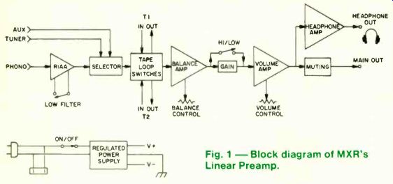
Fig. 1--Block diagram of MXR's Linear Preamp.
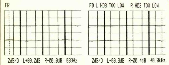
Fig. 2--Frequency response of the phono section.
Fig. 3--Frequency response of the line-level section.
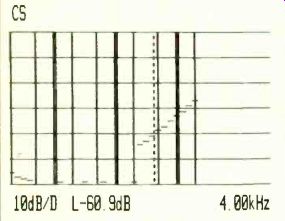
Fig. 4--Separation of the line-level section.
Use and Listening Tests
The simple layout of this preamplifier should appeal to audio purists who have no desire for fancy signal processing circuits, tone controls, loudness controls, and the like. The faithfulness of the sound reproduced by this deceptively simple unit will appeal to anyone who craves accurate music reproduction. I especially liked the way in which the balance control is calibrated; its tapers are arranged so that constant volume levels are maintained even if the control has to be positioned away from its center point.
The front-panel headphone jack, when connected to low-impedance headphones, supplied ample sound for monitoring purposes but was no substitute for a headphone jack found on a power amplifier and intended for serious, full-volume listening. Feeding an 8-ohm load, this headphone jack was able to deliver only 30 mV. Greater power levels were attainable from this jack when higher impedance phones were used.
The two-position gain switch was a welcome feature and one which more preamp makers ought to adopt. What with all the program sources now available for home high-fidelity use, there is a wide range of voltage outputs that a preamp is called upon to handle. To be sure, the master volume control can usually take care of these variations, but it is sometimes inconvenient (and often penalizing to S/N ratios) to have to operate the master volume control at "barely cracked open" or at its full clockwise position.
Besides its totally uncolored reproduction of sound, the MXR 139 Linear Preamp deserves accolades for its incredibly low phono noise and hum. This is all the more impressive since its power supply is not outboard of the chassis, as is true of some other high-end preamps that attempt to achieve this level of performance.
-Leonard Feldman
(Audio magazine, Nov. 1981)
Also see:
SAE Model 2922 Integrated Amplifier (Mar. 1979)
= = = =