Manufacturer's Specifications:
Power Output: 50 watts continuous average per channel, both channels operating into 2, 4, or 8 ohms.
Power Bandwidth: 17 Hz to 100 kHz.
Distortion: Less than 1.0% THD at any power level to 50 watts per channel, from 20 Hz to 20 kHz, both channels operating; typically 0.1% or less, diminishing with output.
Frequency Response: 20 Hz to 20 kHz, ± 0.25 dB.
S/N: 90 dB referenced to rated output; A-weighted, greater than 100 dB.
Input Impedance: 100 kilohms.
Input Sensitivity: 0.75 V.
Power Requirements: 120 V, 50/ 60 Hz, 4 amperes.
Power Consumption: 200 watts at zero signal output (idle); 400 watts at full rated output.
Dimensions: Front panel, 19 in. W x 7 in. H (48.3 cm x 17.8 cm); chassis, 17 in. W x 6 1/2 in. H x 16 in. D (43.2 cm x 16.5 cm x 40.6 cm); depth, including handles, 17 9/16 in. (44.9 cm).
Weight: 56 lbs. (25.5 kg).
Price: $1,665; factory direct, $1,299.
Company Address: 238 Liberty Ave., New Rochelle, N.Y. 10805, USA.
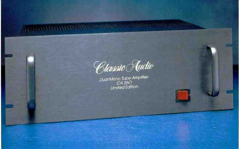
What would you think of a tube amplifier that you could buy on approval? Classic Audio is so confident you will like their amp, they are offering it on a free 10-day home trial. If you decide you don't want the amp, you can return it. Such a deal! Classic Audio is a relatively new company run by George Kaye, the engineer who designed the products for the now-defunct New York Audio Labs.
Looking at the CA260, you find a reasonable package for two independent 50-watt tube amplifiers. Construction is of moderately heavy-gauge steel and consists of a main bottom chassis piece, a top and side cover, and a front panel.
With the top and side cover screwed on, the package has good mechanical integrity and probably would be okay to rack mount.
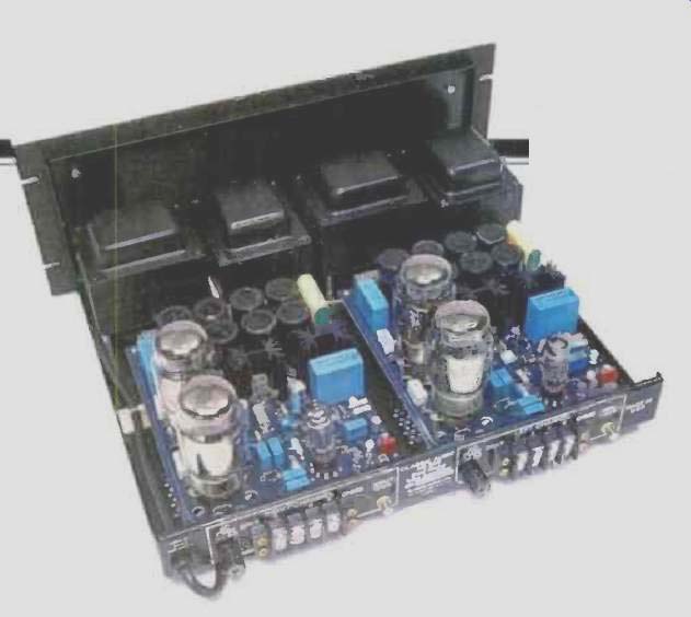
The front panel's only control is an illuminated rocker power switch. Within the amplifier are two circuit boards and two pairs of transformers, power and output, for each channel. On the rear panel are two a.c. line fuses, a common a.c. power cord, two gold-plated RCA signal input jacks, and a four-screw terminal strip for each channel's speaker connections. Impedance taps for 2-, 4-, and 8-ohm loads are provided. There is no provision for matching a 16-ohm load in stereo operation, and this reflects current thinking among some tube amplifier designers that 16-ohm matching is not relevant or needed with today's speakers. A 16-ohm match can be accomplished in the mono mode of operation.
A handy feature of this design is that the amplifier boards are easily removable for service. This could save a lot in shipping costs, should a problem develop.
On the two p.c. boards are all the parts needed for the amplifier circuit-except, of course, the power and output transformers. The most tubelike of these parts are the tubes themselves, a dual-triode driver (12BH7 or 12AU7) and two 6550 output tubes.
The CA260 I reviewed was a "basic" unit, with two optional extras available at $100 each. The first is the inclusion of polypropylene coupling and bypass capacitors; the second option is a pair of toroidal booster transformers that, in conjunction with the existing power transformers. raise the high voltage to achieve a higher power output of some 70 watts or so.
Circuit Description
George Kaye has created an interesting hybrid here. The circuit starts out with a pair of N-channel junction FETs, connected in a common-source differential amplifier as a first stage. A third N-channel junction FET serves as a constant-current source for the input differential amp and is tied to a regulated -5 V source. A balance pot is connected between the sources of the input FETs, with its center tap going to the drain of the current-source device. Adjustment of the source resistor in this current-source circuit allows the operating point of the composite stage to be changed; this is one adjustment for distortion in the circuit. The drains of the FETs are connected to the cathodes of the driver tubes through resistors of fairly high value, on the order of 100 kilohms or more. Additionally, the FET drains are direct but cross-coupled to the driver-tube grids. From each driver tube cathode, a parallel RC network is connected to ground.
The capacitance is on the order of hundreds of microfarads, bypassed by 0.1-uF film units, and the resistance is 15 kilohms. Most of the tube plate current goes to ground through the 15-kilohm resistors. The amount of current going through the FETs is on the order of 100 µA or less. The plates of the driver stage have their load resistors fed from separate hybrid voltage regulators! (I've never seen this before.) One plate-load resistor is fixed and the other is variable, thus permitting an a.c. balance function at this point in the circuit.
The driver plates are also capacitor-coupled to the output tubes' control grids through the usual small (about 1 kilohm) grid-stopper resistors. Incidentally, the term "grid stopper" comes from the use of such resistors to stop parasitic high frequency oscillations in output stages. This output stage is operated with fixed bias, a method whereby the output tubes' grid-leak resistors are returned to a negative supply voltage and the output tubes' cathodes are connected to ground, either directly or through small-value resistors (for measuring plate current by the voltage drop across them). In the other common kind of output-stage biasing, called cathode or self-bias, the cathodes are returned to ground through separate resistors or share a common resistor to ground. The grid-leak resistors are also returned to ground.
The nature of tubes is to be normally on, meaning that they conduct most heavily when there is no potential difference between control grid and cathode. (Junction FETs are also like this, so most tube topologies will work for junction FETs too.) If you have the control grids at ground and some appropriate resistance is placed between cathode and ground, the current flaw through the cathode resistor causes a voltage crop, creating a negative grid-to-cathode voltage or a negative bias for the tube. This reduces the tube's conduction below its zero-bias value.
There is a difference between the way fixed-bias and cathode-bias output stages behave in regard to bias voltage constancy versus power output. In cathode bias, as the plate current increases from its idle value in the usual Class AB operation, the voltage drop across the cathode resistance increases, thereby increasing the negative grid bias and tending to cut the tubes off (sliding bias, if you will). The net result is that the bias voltage for the output stage is not constant but increases for full output, and the available power is less than with fixed bias. In the CA260, each output tube grid-leak or return resistor goes to a separate bias pot, thus allowing adjustment of each tube's current-a common arrangement in fixed-bias tube amps.
In his literature. George Kaye says that "the output circuit is derived from the famous McIntosh output circuit and output transformer with the tertiary feedback cathode winding." From what I can see, the output circuit and transformer of the CA260 are of a simpler type, used in some of Mclntosh's integrated amplifiers. They are not as complex as the output circuit and transformer used in such McIntosh power amplifiers as the MC40 and MC275. Those McIntosh tube power amplifiers of yesteryear had output stages that operated with equal loads in their plate and cathode circuits, thereby requiring tremendous drive voltage to the output stage. This voltage was achieved by bootstrapping the plate-load resistors for the driver stage from appropriate points in the output stage. Further, the output tubes were operated as true pentodes, with a special winding to drive the screen grids in order to keep the screen-to-cathode voltage constant (a good definition of pentode operation). Since the plate, cathode, and screen circuits all had about the same amount of a.c. swing-and, consequently, the same number of turns in the output transformer-these transformers could be and were made with all these wires wound together. This gave tremendous coupling quality to the transformer, with resulting low leakage inductance and interwinding capacitance. In fact, McIntosh amps were operated virtually Class B. I remember that you could put your hands on the output tubes and not get burned. Don't try this on any other tube amp! Anyway, on to the output circuit actually used in the CA260. The tube cathodes are tied to a grounded center tapped winding on the output transformer. This connection provides some local output-stage feedback, said to be on the order of 10 dB. The output tubes' plates are connected to a winding which has a center tap connected to an unregulated +475 V supply. There are no screen taps on this winding; the screen grids are tied together and connected to a regulated +350 V supply.
"Aha," you say, "pentode operation of the output tubes!" Not quite. Pentode operation, by definition, requires constant screen-to-cathode voltage. In this circuit, the screen voltages don't move with respect to ground, but the cathode voltages do. In effect, the moving cathodes cause negative feedback in the control-grid circuit and the screen circuit by making the relative screen-to-cathode voltage increase or decrease in phase with the plate-to-cathode voltage. (This is what happens in normal "ultralinear" operation, where the screen grids move in phase with the plates, but by a lesser amount, and the cathodes are at ground and not moving.) There are two more windings on the output transformer.
One of these, the output to the speaker connections, is floating--i.e., not connected to ground. This would allow the user to drive both inputs of the amp in parallel and to connect the outputs in series to a single load. Try that with a half- or full-bridge solid-state design! The last winding on the output transformer is used for the negative feedback which encompasses the whole circuit. One end of this winding is grounded, and the other feeds a resistor that goes back to the inverting input of the input differential amp.
A shunt resistor to ground at the inverting input sets the overall gain in concert with the series feedback resistor.
The CA260's power supply has some out-of-the-ordinary features right in the primary circuit of its transformer. First, the power switch works on both sides of the a.c. line. Second--and more significant--a solid-state surge limiter, in series with the primary winding, limits in-rush current at turn-on. This device's resistance is relatively high when cold and then becomes much lower, almost negligible, when warmed up first by the draw from the tube filament and then by the plate-current draw of the amplifier. This surge limiter will undoubtedly increase the life of the CA260's power-supply components. Another solid-state device, a metal oxide varistor (MOV) placed across the primary winding, helps to limit the effect of transient line spikes entering the power supply.
The power transformer has two secondary windings, one for high voltage and the other for tube filaments. The high voltage winding feeds a two-diode, full-wave voltage doubler terminated in two banks of photoflash capacitors connected in series. Each bank consists of four 800-µF, 330-V capacitors in parallel; the composite high-voltage filter capacitance for the two banks in series is 1,600 µF. That's a lot of energy storage in a small volume. This unregulated high voltage, +475 V, directly feeds the center tap of the output transformer. Additionally, this supply feeds a solid-state regulator that provides +350 V to the output-stage screen grids and to the inputs of two more high-voltage regulators that feed the plate resistors in the driver-tube stage.
The first regulator for the screen supply consists of two regulators in cascade or series. First, a zener-followed pre regulator, using two Darlington-connected NPN transistors, stabilizes the d.c. voltage at something between 475 V and the final output 350 V--I'd guess about 360 to 370 V. As the final part of this two-stage circuit, a three-terminal regulator is floated up with a voltage divider between its output and return terminals and ground to provide the final regulated output of 350 V. For the 335 V for the driver-tube plates, another kind of regulator circuit is used. A dual bi-FET op-amp is powered with its positive supply connected to 350 V and its negative supply connected to the bottom (ground) end of two zener diodes in series from the +350 V supply. The resistance to ground that provides the zener current is split into two separate resistors in series, to share heat dissipation. The midpoint of the upper zeners, which are probably 15-V units, is connected to the positive input of both sections of the dual op-amp and provides a reference voltage of about 335 V for the two regulators. Two N-channel junction FETs act as source followers, with their drains connected to 350 V. The output of the op-amps drives the gates. Finally, the sources are the outputs of these regulators and are also fed back to the negative inputs of the op-amps to form the negative-feedback regulating loops.
A little philosophical point here: Could the seeming advantage of using separate regulators to feed the plate resistors be a disadvantage sonically? What I mean by this is, if the regulators' "solid-state sound" signatures got into the output stage, those signatures might not be cancelled by the output circuit's push-pull action, because the signatures of two separate regulators are not identical. On the other hand, the sonic signatures of a single regulator feeding both plate-load resistors would be cancelled in the output-stage transformer.
The last little detail of the power supply concerns the tube heater supply. This is quite conventional, with about 6.3 V a.c. being applied to the tube heaters from the low voltage winding of the power transformer. One side of this winding is grounded, and a half-wave rectifier (along with a filter capacitor and a three-terminal regulator) creates the -5 V supply that is the current source for the J-FET input stage of the amp.
Measurements
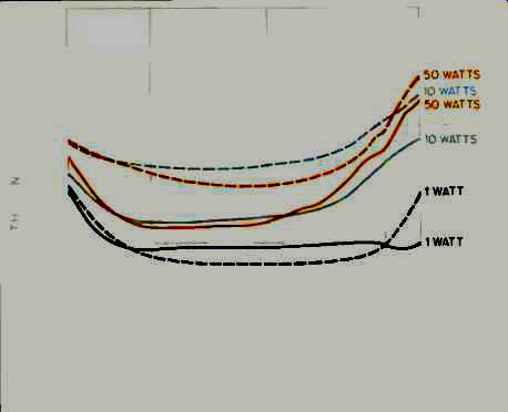
Fig. 1--THD + N vs. frequency at several power levels, for 8-ohm load on
8-ohm output taps. Solid curves are for left channel, dashed curves are
for right.
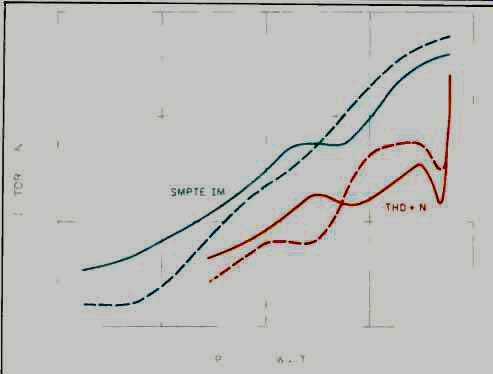
Fig. 2--SMPTE IM and THD + N vs. power output for 8-ohm loads on 8-ohm taps.
THD + N is for 1-kHz test signal, with distortion products measured from
400 Hz to 80 kHz. Solid curves are for left channel, dashed curves are for
right.
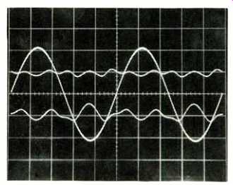
Fig. 3--Response to 10-watt, 1-kHz sine wave. Distortion products shown
are for left channel (top) and right channel (bottom).
The instruction manual that comes with the CA260 is pretty good and contains a rather detailed section on maintenance. To adjust the amplifier for best performance, the manual suggests adjusting the individual output-tube bias pots-along with the first-stage current-source and driver plate-load adjustment pots--for minimum distortion, using a 1-kHz test frequency. This implies that the static plate currents for each output tube may be different when such a procedure is completed. The result would be some amount of unbalanced d.c. in the primary of the output transformer.
The effect of unbalanced d.c. is to push the flux in the core off center so that saturation occurs sooner in one half-cycle than in the other. This makes low-frequency distortion and SMPTE-IM distortion increase. When I received this amp for review, I connected it into my system and measured the output tubes' idling currents after a suitable warm-up time. I was surprised to find that the plate currents were quite low-around 20 to 30 mA per tube. I also noticed that all the trim pots in the amp had their adjustments sealed, presumably at the factory. I decided to just listen and measure, with no trim pot tweaking.
In the lab, after testing the amp, the individual output-tube plate currents were measured and found to be 29.2 and 24.2 mA for the two tubes of the left channel and 22.9 and 20.9 mA for the two right-channel tubes.
Figure 1 shows THD + N as a function of frequency and power output for both channels, with 8-ohm loads on the 8 ohm taps. As power levels increase, the right channel has more distortion than the left-due mostly to its lower idling current. Figure 2 shows 1-kHz THD + N, along with SMPTEIM distortion, for 8-ohm loading on the 8-ohm taps. Studying these curves and, more informatively, looking at the harmonic and IM residues as a function of power, I concluded that the dominant nonlinearity is of the type caused by low gain at the origin, or under-biasing.
I measured distortion versus power, for 8- and 4-ohm loads, on their respective matching taps. I found the distortion to be about the same for each-not always the case in other tube power amps. Shown in Fig. 3 is the harmonic distortion residue for 10 watts output at 1 kHz for the two channels. The top distortion trace, at 0.15%, is for the left channel; the other, at 0.37%, is for the right. Neither residue waveform is very simple or low order.
To see how distortion might vary as a function of mismatching, I measured 1-kHz THD + N at 30 watts output for a 4-ohm load on the 2-, 4-, and 8-ohm taps. The results were 0.38%, 0.35%, and 0.96%, respectively, for the left channel and 0.2%, 0.55%, and 1.25% for the right. Next, I measured the maximum 1-kHz power at visual onset of clipping for the same loading conditions and found these power levels to be 40, 53, and 55 watts for each channel. With this amp, there is considerable latitude for mismatching, but best performance is likely when using the tap closest to the rated nominal impedance of your speaker.
Since the Classic Audio CA260 has such low overall feedback, its voltage gain will vary with how it is adjusted--not radically, but somewhat. I obtained readings that showed 25.8 and 25.5 dB of gain for the left and right channels, respectively. IHF sensitivities were 145 mV for the left channel and 150 mV for the right.
Next, I looked at crosstalk between channels. "What?" you ask, "How can there be crosstalk in a dual mono design?" Well, there is a tiny bit at high frequencies. With 8-ohm loading on the 8-ohm taps, the undriven input terminated in 1 kilohm, and a reference drive level of 10 V rms, crosstalk in the right-to-left direction was essentially down in the noise. In the left-to-right direction, however, crosstalk rose above the noise by about 3 dB at 5 kHz, increasing to 10 dB above the noise at 20 kHz.
Hum and noise measurements appear in Table I for various bandwidths and for the left and right channels. Inputs were terminated in 1 kilohm.
Since the CA260's output impedance was initially found to be rather high, I decided to measure it by comparing open circuit to loaded-output voltages and then computing the output impedance from this information. For once, even though the output impedance is high, it is essentially constant over the whole audio frequency range. Output impedance is roughly half the tap impedance, thereby resulting in a damping factor of about 2. Output impedances and damping factors are shown in Table II for the 2-, 4-, and 8 ohm taps.
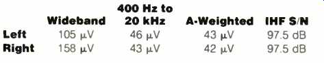
Table I--Hum and noise, with inputs terminated by a 1-kilohm resistance.
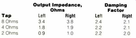
Table II--Damping factors and output impedances. Damping factor is essentially
flat from 20 Hz to 10 kHz and is slightly lower at 20 kHz.
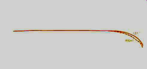
Fig. 4--Frequency response at 1 watt output, for 8-ohm load on 8-ohm taps.
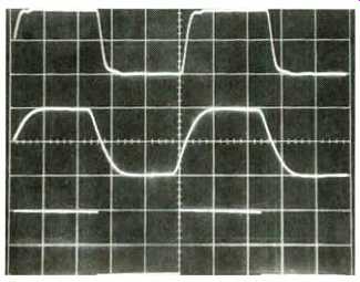
Fig. 5--Response to square wave. Top trace is 10 kHz with 8-ohm resistive
load on 8-ohm taps. Middle trace is 10 kHz with 2-µF capacitance across 8-ohm
load. Bottom trace is 40 Hz with 8-ohm load. Scales: Vertical, 5 V/div.;
horizontal, 20 µS/div. (top and middle) and 5 mS/div. (bottom).
Frequency response, measured with 8-ohm loading on the 8-ohm taps, is plotted in Fig. 4 for both channels. Figure 5 shows square-wave performance of the CA260 at its 8-ohm taps. Results were similar on the other taps with equivalent loading; this is a testament to the quality of the coupling between the secondary windings and the other windings in the output transformer. The top trace of Fig. 5 is for a 10-kHz square wave at 10-V peak-to-peak amplitude loaded by 8 ohms. Rise- and fall-times, with 8-ohm loading, were about 4µS and pretty constant right up into clipping.
In the middle trace, the effect of paralleling 2µF across the 8-ohm resistor is seen. Increasing the capacitance merely rolls off the response more; there is no ringing, just increasing rise- and fall-times. This behavior is different from that of most amplifiers, whose square-wave performance usually looks textbook-perfect with resistive loading but shows ringing with capacitive loading. The CA260's nice performance with capacitive loading suggests that it would be great for driving electrostatic speakers. The bottom trace of Fig. 5 is for a 40-Hz frequency. Evident here is a good, extended low-frequency response.
Output power levels for dynamic and clipping headroom were found to be 64 and 56 watts, respectively, yielding a dynamic headroom figure of 1.07 dB and a clipping headroom of 0.5 dB.
Use and Listening Tests
Equipment used to evaluate the CA260 power amp included an Oracle turntable fitted with a Well Tempered Arm and Koetsu Black Goldline pickup, a California Audio Labs Tempest CD player, a Nakamichi 250 cassette deck, a Technics 1500 reel-to-reel recorder, a Cook-King reference tube preamp, a Sumo Athena preamp, a Goldmund Mimesis 7 preamp, a Dyna PAS-2 preamp, and YBA3, Goldmund Mimesis 6, and Motif MS100 power amplifiers used to drive Siefert Research Magnum Ill speakers and Stax Sigma headphones.
Operationally, the CA260 worked flawlessly; there were no glitches or surprises. To me, the CA260 doesn't sound like the usual older tube amp, in the sense of being mellow and nicely musical on most program material. Tonally, the sound is a bit on the bright side. Definition and detail seem quite good, although I get the feeling that this comes at the expense of some edginess and irritation. The sense of air around instruments is good but not excellent. Depth delineation is not as good as on other amplifiers I have on hand, and I get a distinct sense that room or hall reverberation dies out too quickly. Bass punch and impact are very good for an amp rated at 50 watts per channel.
Nit-picking aside, this amp really sounds pretty good and, considering the price, it probably is well worth looking into. As Classic Audio says in a brochure included with the amp, "It's got more watts, more iron, and bigger tubes than the competition." So y'all c'mon down and give it a try, ya hear?
-Bascom H. King
(Audio magazine, Nov. 1989)
Also see:
Classe Audio DR-3 Amp (Jul. 1986)
Conrad-Johnson Premier Seven-A Preamp and Evolution 2000 Amp (Jun. 1992)
David Berning EA-2101 Amp & TF-12 Preamp (Dec. 1991)
Counterpoint SA-220 Power Amp (Jul. 1990)
= = = =