
Manufacturer's Specifications:
System Type: Three-way, vented box enclosure with external electronic high-pass alignment filter and equalizer.
Drivers: One 12-in. (300-mm) polymer cone woofer, one 5-in. (126 mm) Kevlar cone midrange, one 1 in. (26-mm) metal dome tweeter.
Free-Field Frequency Response (With Filter/Equalizer): 20 Hz to 20 kHz, ±2.5 dB;-6 dB at 17.5 Hz and 25 kHz.
Dispersion (20 Hz to 15 kHz): Horizontal, +0,-3 dB within ±30° of axis; vertical, ± 1 dB within ±5° of axis.
Sensitivity: 87 dB SPL at 1 meter for 2.83 V rms.
Crossover Frequencies: 380 Hz and 3 kHz.
Impedance: 8 ohms nominal, 4 ohms minimum.
Recommended Amplifier Power: 50 to 600 watts per channel.
Dimensions: 39 11/16 in. H x 17 in. W x 22 in. D (100.8cm x 43.2 cm x 55.9 cm).
Weight: 110 lbs. (50 kg) each.
Price: $5,900 per pair.
Company Address: B & W Loudspeakers, P.O. Box 653, Buffalo, N.Y. 14240.

Very few speaker systems are held in high regard by both recording engineers and high-end audio people, but the B & W 801 Matrix Series 2 is just such a system. Even though promoted primarily as a professional monitor loudspeaker, it enjoys high popularity in the audiophile home market. The recording engineer places high emphasis on such characteristics as reliability and high acoustic output capabilities (among other qualities), whereas the audiophile stresses such qualities as accuracy, imaging, and frequency response that is wide, flat, and smooth. The 801, because it embodies all these attributes, appeals to both sides of the user community.
B & W Loudspeakers, one of Britain's premier loudspeaker companies, was founded by John Bowers in 1966 as Bowers and Wilkins Loudspeakers Ltd. The company had its humble beginnings in a workshop behind the Bowers and Wilkins "Hi-Fi Shop" in Worthing, England, where Bowers would tinker and improve loudspeakers for the shop's clientele. B & W now employs over 250 people in the U.K. and supports a dedicated research and development facility that employs over 20 full-time staff personnel.
B & W has been a world leader in applying high technology to the field of loudspeaker development and manufacturing, and it pioneered the use of laser interferometry in the study of loudspeaker vibration. It is the only company licensed to use DuPont's high-strength material Kevlar, which is used in the midrange cone of the 801. The 801 is used quite extensively in Europe and elsewhere for monitoring classical music recordings by such companies as EMI, Deutsche Grammophon, Decca, and Sony Classical.
The 801's most striking feature is its physical appearance. With its massive front-vented bass enclosure and external top-mounted mid/high-frequency head assembly, and individual grilles, it makes quite a design statement; you either love it or you hate it. (My wife is in the latter category-she calls them the robots. When I first set them up in the listening room, our dog came in and barked at them!) The industrial design of the 801 was by the celebrated designer Kenneth Grange, who has done work for Kenwood, Kodak, Wilkinson razors, and the British government, among others.
The enclosure is available in several real wood veneers including black ash (the review sample finish), walnut, rosewood, and teak, and in satin white. B & W has gone to great lengths to reduce cabinet resonances and cabinet wall radiation by the use of sophisticated construction methods. These include techniques such as structural foam bonded with Fibrecrete, used in the head assembly, and honeycomb bracing used in the bass enclosure (this is where the "Matrix" term comes from). The drive units of the 801 represent B & W's best efforts in design and development. The high-excursion bass driver has a cone made of a specially formulated polymer plastic compound that is heavily damped to reduce unwanted colorations. The driver has a large, 13-lb. (6-kg), dual ceramic magnet assembly that provides the high magnetic field required for proper control of the cone's motion. The cone of the 5-in. midrange driver is made from woven Kevlar, which provides high strength, damping, and low mass for accurate midrange operation. The tweeter incorporates a metal-dome diaphragm designed and analyzed using B & W's laser interferometry and finite-element analysis techniques. Because of the metal dome's high stiffness and low-mass structure, the first resonant breakup mode is far above the audible frequency range (my measurements show the first breakup to occur at about 27 kHz). The low-frequency enclosure of the 801 is a vented-box design with the box (Helmholtz) resonance frequency placed rather low, at 19 Hz. The box is tuned with a flared end 7-in.-long (178-mm) tube of about 2 1/2-in. (57-mm) diameter. An active high-pass alignment filter is supplied, which connects to a system tape loop or between the preamp and amp. With this filter, the system is a pure sixth order Butterworth, high-pass design conforming to Thiele's alignment No. 15 (for you Thiele-Small buffs). The driving filter is a second-order high-pass filter with a Q of 2, which provides 6 dB of boost at 20 Hz while rolling off by 12 dB/ octave at lower frequencies. This filter equalizes the system's response flat (-3 dB) to 20 Hz and provides a steep roll-off below to decrease the system's sensitivity to high-level below-band subsonic energy. This popular vented-box alignment is used in several other consumer and professional systems, including many subwoofers. The system, of course, does not have to be used with the filter. Without the filter, the system's low-frequency response has a fourth order Bessel response with a gradual roll-off, about 3 dB down at 30 Hz and 9 dB down at 20 Hz. This is not a bad response target for any system.
The mid/high-frequency head assembly is mounted to the top of the low-frequency cabinet with a long threaded bolt that passes through the head and screws into the woofer cabinet. Connections between the head and woofer cabinet are made with a mating pair of Switchcraft three-pin XLR connectors (standard low-impedance pro microphone connectors). The head assembly is shipped attached to the bass cabinet but must be removed and then replaced by the user after fitting a separately packed foam and fabric top cover on the cabinet.
The crossover (together with the protection circuitry) is wired on a large printed-circuit board that is mounted underneath the low-frequency enclosure and covered with a 1/4-in.-thick piece of hardboard. Not counting the protection circuitry components, the rather elaborate crossover consists of 25 components: 11 capacitors, eight inductors, and six resistors. Liberal use was made of impedance-correcting networks across the woofer and tweeter terminals.
Input connections to the 801 are through a dual set of gold-plated, finger-tightened binding posts with standard 3/4-in. (19-mm) spacing. Internal connections from the input terminal panel to the p.c. board are made with 50-strand van den Hul wire. Dual sets of input connectors are provided for optional bi-wiring (separate cable connections from the amplifier to the low-frequency and high-frequency sections of the system, which potentially may reduce any intermodulation of the high frequencies by high-current low frequency signals flowing in a common connection cable). Conversion to the bi-wiring configuration is accomplished by removing the bottom crossover cover, taking out two wire links in a screw-type terminal strip, and using the dual input connectors for the separate low- and mid/high-frequency drives.
The protection circuitry, which B & W calls an "Audio Powered Overload Circuit" (APOC), consists of two separate two-transistor circuits controlling relays with sense connections to each of the driver terminals. When energized, the relays disconnect the drive respectively to the woofer and the midrange/tweeter combination and illuminate a warning LED on the front of the cabinet. When the overload passes, the drivers are reconnected and the LED is extinguished. An overload sensed in either the midrange or the tweeter would disconnect both units at the same time. This dual protection circuitry ensures proper protection for the drivers even when the system is bi-wired. The detection circuitry consists of a simple, voltage-sensing half-wave diode rectifier feeding a large capacitor. Voltage dividers are used across each driver to set the trip point and attack time of each circuit. Power for the protection circuits is derived from the audio input with rectification and zener Both protection circuits are identical, except for different charge-time constants (roughly 0.4 second for woofer and 0.1 second for midrange/tweeter) that govern the length of time it takes to cut off the offending signal. The discharge time constants (hence release time) of the sense circuits appeared to be on the order of about 0.5 second. This type of circuit will essentially protect the drivers from long-term continuous overloads but allow short-term transients to pass through unimpeded to each driver. (In the high-power tone burst power tests described later, the protection relays did not energize at any time.) According to B & W, the protection relays are set to energize at the following continuous sine-wave rms input voltages: 100 Hz at 40 V (200 watts into 8 ohms); 1 kHz at 43.5 V (236 watts), and 10 kHz at a level of 13 V (21 watts). All had a ± 1.5 V tolerance.
The systems have pre-attached furniture castors for easy movement and floor spikes that can be attached for greater stability on a carpeted floor. B & W also has optional stands that raise the system off the floor for situations where greater height is needed The 801 has generated a thriving after market for various items aimed at improving it. These include such items as internal cable harnesses, replacement input terminals, and stands. With the suggestion of B & W's North American public relations person, I was supplied with a pair of special stands for the 801 from Sound Anchors, Inc. ( Palm Bay, Fla.). These stands are composed of an extremely rigid, damped, metal structure, which is bolted to the base of the 801; it provides a three-point spiked contact with the floor and simultaneously raises the speaker by about 11 in. Provided are means for easy adjustment of the system's vertical aiming angle. Due to logistic reasons and time constraints, I did not properly evaluate these stands but would recommend them for installations where the 801s are going to be permanently mounted and can benefit from the features that the stands provide.
Measurements
A number of measurements were performed on the 801 to assess its performance. These included on- and off-axis frequency response, energy-time curves, impedance versus frequency, harmonic and IM distortion, and maximum peak input and output capabilities. The measurements were performed at a number of locations, including my own listening room and lab and outdoors on my driveway. Measurement equipment consisted of a Techron TEF System 12 Plus Time-Delay Spectrometry (TDS) analyzer, B & K 4007 condenser microphone, Crown Macro-Tech MA-2400 power amplifier, and Leader signal generators, attenuators, voltmeter, and oscilloscope. The system was evaluated using elevated free-field, near-field, and ground-plane measurement methods.
The on-axis system frequency-response measurement was done at a distance of 2 meters, normal to the front baffle, on an axis halfway between the tweeter and the midrange driver. The input level was 2.83 V rms, which is equal to a level of 1 watt into the system's nominal 8-ohm impedance. The on-axis response was corrected to the standard distance of 1 meter for display of the data, and a tenth-octave smoothing filter was used to smooth the response for easier interpretation.
The 1-watt, 1-meter, on-axis frequency response of the 801 is shown in Fig. 1. The curve was taken with all grilles on. Note that this graph covers the wider range of 10 Hz to 20 kHz rather than the usual 20 Hz to 20 kHz. Also shown is the low-frequency effect of the high-pass alignment filter.
The response is quite good without the filter, extending from 42 Hz to 20 kHz (±2 dB); with the filter, the response is extended down to 25 Hz within the same envelope, being only about 3.5 dB down at 20 kHz. The response above 20 kHz (not shown) reveals a dip at 23 kHz and a peak at 27 kHz, which is presumably due to a resonance of the tweeter's metal dome.
The filter, in addition to significantly boosting the response between 18 and 50 Hz, rolls off the response below 15 Hz, thus minimizing the effect of possible high-level subsonic energy in the program material. This is fortunate, because later measurements in this review revealed that the system could handle only about 10 to 15 watts of input below 12 Hz without exceeding the linear excursion range of its vented-box-loaded woofer. A vented-box enclosure essentially unloads its woofer about a half octave below its box-resonance tuning frequency (box tuning for the 801 is about 20 Hz). Averaging the axial response over the range of 250 Hz to 4 kHz yielded a sensitivity of 86 dB SPL, within 1 dB of the manufacturer's rating of 87 dB at 1 kHz. A separate test, comparing the axial response of both right and left speakers in the range from 200 Hz to 20 kHz (not shown), yielded a moderately good match of about ± 1 dB. The level differences were more or less randomly distributed over this frequency range.
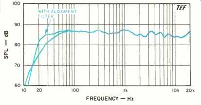
Fig. 1--On-axis frequency response. Also shown is the effect of the alignment
filter and equalizer on the low-frequency response.
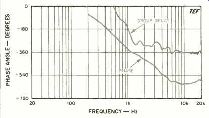
Fig. 2--On-axis phase response (lower curve) and group delay (upper curve),
corrected for tweeter arrival time.
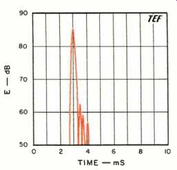
Fig. 3--One-meter on-axis energy/time curve, measured with all grilles on.
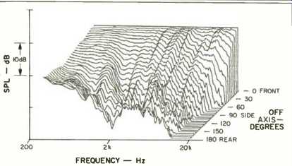
Fig. 4-Horizontal off-axis frequency responses, taken from the front, around
the side, and to the rear of the speaker and normalized to the on axis response;
see text.
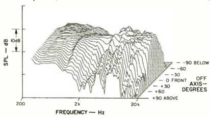
Fig. 5-Vertical off-axis responses taken from below, up the front, and to the
top of the speaker and normalized to the on-axis response.
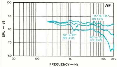
Fig. 6--Mean horizontal response, derived from data of Fig. 4; see text.
Figure 2 shows the on-axis phase and group-delay responses of the system, corrected for the time arrival of the tweeter. The phase response (lower curve) exhibits moderate phase rotation of 270° between 1 kHz and 20 kHz. The group delay (upper curve) indicates that the midrange trails the tweeter by about 0.20 mS (200 µS), which corresponds to a distance of 2.7 in. (69 mm). This time offset represents approximately 0.6 wavelength, or 216°, at the crossover frequency of 3 kHz.
The woofer's excursion capability was determined by sweeping with a high-level sine wave covering the low frequency range. The maximum linear excursion capability of the woofer was a healthy ±0.25 to ±0.3 in. (0.5 to 0.6 in., peak to peak). In the upper bass range of 50 to 100 Hz, this large excursion capability was mostly nullified by rather high amounts of "dynamic offset" or "oil canning" problems.
(See Audio, September 1989 for more information on the oilcan effect.) At 50 Hz, the cone would displace outward at voltage levels of 14 V and above (roughly 25 watts into 8 ohms), with an increase of second-harmonic distortion. The test of harmonic distortion versus power shown later in this review unfortunately does not show these problems because the standard test frequencies of 41.2 (E1) and 110 Hz (A2) straddle the problem frequency area.
The woofer had an effective radiating diameter of about 10 1/2 in. The box was well sealed and had no leaks even with high levels at low frequencies. The vented-box port did exhibit significant air-rush chuffing sounds, due to vent air turbulence, when the system was driven above 10 V rms with a sine wave at frequencies near box tuning (15 to 25 Hz). The chuffing sounds appeared to originate inside the cabinet, at the inlet to the vent tube. The enclosure sidewalls were very rigid (inert would be a better word!) and displayed absolutely no detectable sidewall vibrations. However, the 1/4-in.-thick hardboard panel covering the crossover network on the bottom of the cabinet (supported only by its edges) did resonate quite strongly, in the range from 105 to 112 Hz, with high-level signals. I suggest leaving this panel off for serious listening. The panel also flunked the finger-tap-and-listen test.
The 1-meter, 1-watt, on-axis energy/time response (ETC) is shown in Fig. 3, for a test signal swept over the range of 200 Hz to 10 kHz. This ETC represents mostly the tweeter's response and emphasizes energy in the range of 2 to 9 kHz.
The response is quite compact and only followed by three lower level arrivals, which are more than 23 dB down from the main arrival.
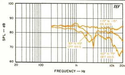
Fig. 7--Mean vertical response, derived from data of Fig. 5.
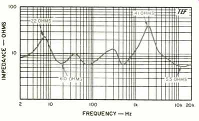
Fig. 8--Magnitude of impedance; note the logarithmic impedance scale.
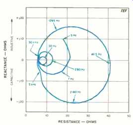
Fig. 9--Complex impedance, showing reactance and resistance vs. frequency.
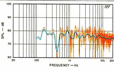
Fig. 10-Three-meter room response, showing both raw and smoothed data; see
text.
The off-axis response of the system was measured in two different ways. The first method displays the data in a three-dimensional "waterfall" format, and the second method closely follows the way the on- and off-axis response curves are measured and derived at the Canadian NRC's test facilities (see Audio, September 1989 for more information). Figures 4 and 5, respectively, show the horizontal and vertical off-axis frequency response curves of the 801 in the "3-D" format. These curves were derived from frequency response measurements made approximately at 5° increments along the major horizontal and vertical planes of the system. No additional smoothing was done on these curves except for the constant bandwidth smoothing that results from the TDS measurement process.
These graphs have a logarithmic frequency scale and are normalized to the on-axis frequency response. The normalization makes the on-axis curve a straight line and clearly shows the differences between on- and off-axis curves.
The horizontal "3-D" off-axis curves in Fig. 4 indicate well-behaved off-axis behavior, with high-frequency coverage up to 15 kHz out to about 30° off axis. The vertical off-axis curves in Fig. 5 indicate quite symmetrical up-down behavior through the upper crossover region from 1.5 to 6 kHz. This symmetrical behavior implies no "lobing error" and indicates that the relative phase angles of the midrange and tweeter acoustic outputs are very close together in the crossover region. This low relative phasing has the beneficial effect of directing the main lobe of the system's crossover acoustic output straight ahead, toward the listener, and thus minimizes response changes with vertical listener location.
Electrical measurements (not shown) of each driver's crossover voltage drive indicated that the tweeter was rolled off below 4 kHz at 18 dB/octave. The midrange was rolled off below 400 Hz at 12 dB/octave (with additional response shaping just below cutoff) and above 3 kHz at 18 dB/octave.
The woofer had a 24-dB/octave roll-off above 300 Hz. These steep crossover roll-off rates minimize the effect of the crossover on the system's directional response. Note that the total crossover response is the combination of both the crossover electrical drive and the driver's acoustical response in the region.
The NRC-style mean horizontal and vertical on- and off-axis response curves of the system are shown in Figs. 6 and 7. These responses were derived from the previous "3-D" data by calculating response averages of several adjacent curves in specific on- and off-axis angular regions.
The mean axial horizontal response curve (Fig. 6) is fairly flat and smooth, although exhibiting a slight droop as frequency increases, and falls within a ±2 dB envelope out to 20 kHz. This curve represents the average frequency balance within ± 15° of the axis horizontally but on-axis vertically. The 30° to 45° response is also quite smooth but rolls off at about 4 dB/octave above 5 kHz. The 60° to 75° response, although somewhat rougher, fits in an envelope of ±4 dB out to 8 kHz, where the level drops quickly at higher frequencies. The smooth wide-angle horizontal response indicates that the 801s should maintain good stereo images over a fairly broad horizontal listening area but with some high-frequency loss at extreme angles.
Except for a slight peak at 1 kHz, the mean vertical axial response (Fig. 7) is very close to the horizontal mean axial response and actually slightly smoother. Because ± 15° includes both sitting and standing listeners, this curve indicates that the tonal balance of the system should change very little with changes in listener height.
The 30° to 45° mean response has a hole 2/3-octave wide, centered at 3 kHz. This is due to the unavoidable interference effects of the spatially separated midrange and tweeter (the 4.5-in. center-to-center spacing corresponds to about one wavelength at 3 kHz). The in-phase crossover condition of the midrange and tweeter actually places the interference nulls symmetrically in both the up and down 30° to 45° regions. Indeed, analysis reveals that two in-phase acoustic sources separated by one wavelength will have symmetrical off-axis nulls in the polar response at up and down angles of about 35°. Fortunately, the rather steep acoustic roll-offs of the crossover confine the aberrations to a relatively narrow frequency range, 2/3-octave wide. The 60°-to-70° mean response has a depression in the range from 2 to 3 kHz, and drops quickly above 9 kHz.
Figure 8 shows the input impedance of the 801 plotted over the four-decade-wide range of 2 Hz to 20 kHz with a logarithmic vertical scale. A minimum impedance of 5.5 ohms at 12 kHz and a maximum of 41 ohms at 1.9 kHz was measured. This range of nearly 8 to 1 in impedance magnitude will make the 801s somewhat cable-sensitive, especially for long runs of smaller diameter wire. Series cable resistance should be less than about 70 milliohms, to limit peak-dip response variations in voltage drive to less than 0.1 dB. Figure 9 shows the complex magnitude-phase (Nyquist) polar plot of the impedance over the range of 5 Hz to 30 kHz. The curve is very well behaved, with no minor loops exhibited. This indicates no spurious higher order resonances in the cabinet or the driver moving systems. The system attained a maximum positive (inductive) phase angle of 47° at 1.1 kHz and maximum negative (capacitive) phase angle of 55° at 2.8 kHz. These maximum phase angles should present no problems to any reasonably well designed amplifier.
Figure 10 shows the 3-meter room curve of the system (both raw and sixth-octave smoothed data shown), located in the right stereo position, with the test microphone placed at ear height on the sofa where the listener normally sits. The system was swept from 100 Hz to 20 kHz with a 2.83 V rms sine-wave signal (equivalent to 1 watt into the nominal 8 ohm impedance). The resultant sound levels can be read directly off the graph.
The parameters of the TDS sweep were chosen to include the direct sound plus 13 mS of the room's reverberation.
This amount of room sound represents approximately the effective averaging of the human ear, with its emphasis on the direct sound plus early energy arrivals.
The curve is quite well behaved and flat except for a large hole in the response at 400 Hz. Even though this first appears to be a floor bounce problem, it was found not to be. Stacking pillows on the couch just below the test microphone mostly corrected the problem and indicated that a reflection or interference from the couch was the culprit. I should have made a measurement with a person actually sitting on the couch to see what the effect was. The problem frequency range is very close to the 801's lower crossover frequency, where the acoustic source is spread between the woofer and midrange. A spread source tends to decrease the floor bounce effect.
Harmonic and intermodulation (IM) distortion is displayed in four graphs. Figures 11, 12, and 13, respectively, show the spectra for single-frequency harmonic distortion versus power level at the musical notes of E1 (41.2 Hz), A2 (110 Hz), and A4 (440 Hz). These curves indicate the level of harmonic distortion that is generated by the system with the application of a single-frequency sine wave at power levels covering the range of 0.1 to 100 watts (-10 to 20 dBW, a 30-dB dynamic range). The power levels were computed using the rated system impedance of 8 ohms. At no time did the protection circuitry engage during these tests or the later tests of peak power.
The curves were run by successively increasing the sine wave input level in 1-dB increments (each step about 26% higher in power than the previous level.) At each power level, a swept spectrum analysis was done over a frequency range covering up to the fifth or sixth harmonic. Two precision 1-dB/step attenuators were used in the setup, one in the send path and one in the receive path, to ensure that the power level steps were accurate. The receive attenuator provides a constant fundamental level to the spectrum analyzer so that distortion percentages can be directly read off the plotted data scales.
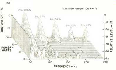
Fig. 11--Harmonic distortion products for the musical tone E1 (41.2 Hz).
Figure 11 shows the E, (41.2-Hz) harmonic distortion data. The non-harmonically related spikes, at lower power levels, are due to measurement setup background noise and are not generated by the loudspeaker. At lower power levels, the second and third harmonics are evident. At higher power levels, the fourth, fifth, and sixth harmonics join the lower ones. The second harmonic is seen to predominate over the whole power range, which indicates a one-sided nonlinearity. Note that 100 watts at 41 Hz generates roughly 104 dB (loud!) at 1 meter with this system.
These distortion percentages, though not the lowest, are reasonable considering the size of the woofer.
The A2 (110-Hz) harmonic data is shown in Fig. 12. The graph shows that only the second and third harmonics were significant over most of the power range. The second harmonic increases gradually with power, reaching a level of only 1.26% at 100 watts. The third harmonic, though somewhat higher, reached only 2.4%. As in the previous graph, all the nonharmonic random-like information shown is not produced by the speaker but is the result of background noise and other effects in the test setup.
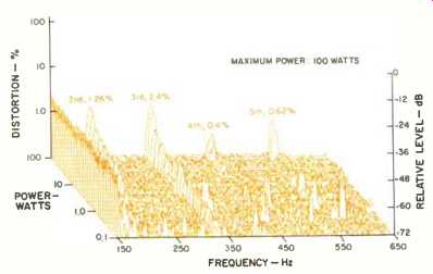
Fig. 12--Harmonic distortion products for the musical tone A2 (110 Hz).
The A4 (440-Hz) harmonic measurements are shown in Fig. 13. As in the 110-Hz measurements, the predominant distortion is a low amount of second and third, with negligible amounts of higher order distortion. For this test, the maximum power was limited to 50 watts because of resistors overheating in the crossover network. Some preliminary testing was done at 100 watts, which caused a pair of power resistors in series with the midrange portion of the network to heat up enough to smell quite badly.
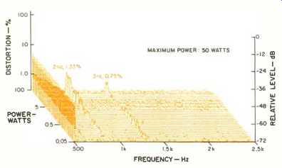
Fig. 13--Harmonic distortion products for the musical tone A4 (440 Hz). The power
was limited to 50 watts because of resistors overheating in the crossover network.
The 41.2-Hz distortion test also caused overheating of a 10-watt power resistor in the woofer part of the crossover (in a Zobel impedance-correcting network in parallel with the woofer, coincidentally tuned to about 40 Hz). I burned my finger on this one while trying to find which resistor was overheating! Note that under normal operating conditions, with program material, resistor overheating should not be a problem. It takes some crazy reviewer like me, doing continuous high-power, narrow-band sine-wave testing, to cause overheating!
The IM on a 440-Hz (A4) tone created by an equal-level (input power, not acoustic output level) 41.2-Hz (E,) tone, is shown in Fig. 14. The IM distortion gradually rises with power, reaching a level of only about 5% at 50 watts. The first-order (f2 ± f1) and second-order (f2 ± 2f,) side frequencies predominated in this power range. These IM levels are quite low, primarily due to the fact that the woofer handles the lower frequency signal and the midrange essentially handles the upper. The maximum power was again limited to 50 watts due to crossover limitations.
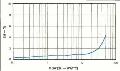
Fig. 14--IM distortion on 440 Hz (A4) produced by 41.2 Hz (E1) when mixed in
one-to-one proportion.
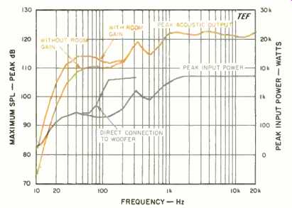
Fig. 15--Maximum peak input power vs. frequency, and maximum peak sound output
(measured at 1 meter on axis), for the input levels shown; see text.
Figure 15 shows the short-term peak-power input and output capabilities of the system, as a function of frequency.
The tests were run by exercising the system with a high-level, shaped, 6 1/2-cycle, sine-wave tone-burst signal. This test signal covers a third-octave bandwidth, with a time duration that increases as the frequency goes down. The duty cycle of the test signal is low enough so that the long-term thermal characteristics of the speaker under test are not exercised.
The test consisted of determining the maximum peak input power-handling capacity and maximum output peak sound pressure levels, in the range of 10 Hz to 20 kHz, at all third-octave center frequencies. The Crown MA-2400 power amplifier, configured in the bridged mode, was used to drive the system. In this configuration, the amplifier can generate short-term peaks of about 5.0 to 5.5 kW (+37 dBW, or ±210 V into an 8-ohm load) depending on the load. The peak input power was calculated by assuming that the measured voltage was applied across the rated 8 ohm impedance.
The test sequence consisted of determining how much of the burst test signal could be handled by the speaker, at each frequency, before either the output sounded audibly distorted or the acoustic output waveform appeared distorted, whichever occurred first. At each frequency, the maximum peak input voltage and the corresponding generated peak output sound pressure level at 1 meter were recorded (Fig. 15).
The maximum peak electrical input power-handling capacity is seen to rise with frequency until about 40 Hz, where it stays roughly constant at about 250 watts and then rises to a peak of 1,650 watts at 315 Hz. Above 315 Hz, the level drops slightly at 500 Hz, then rises smoothly up to about 5.1 kW at 1.6 kHz and stays at this level for all higher frequencies. Above 1.6 kHz, the amplifier's clipping power limit was reached before the speaker's was! The depression at 500 Hz is due to midrange excursion limitations. The system can actually handle more power than the curves show but at the expense of much greater distortion and possible damage risk at higher frequencies.
Initially, I was at a loss to explain why the power handling in the range from 80 to 250 Hz was so low. In this range, the acoustic output waveshape turned into a triangle wave with accompanying high values of harmonic distortion, at levels above 45 V peak (250 peak watts). By comparison, the Dahlquist M907i reviewed in the August issue had about six to eight times higher power-handling on bursts in this frequency range.
Before you say, "So what, 250 watts is sufficiently high for practical purposes," realize that with transient burst signals the subjective loudness of the output is significantly lower than an equivalent continuous signal of the same peak power. In a side-by-side comparison, the highest clean burst output of the 801 at 125 Hz sounded rather anemic compared to the M907i's output.
To track down the cause of the power reduction, I first ran a peak input power test with direct connection to the woofer, which is shown in Fig. 15. This indicated that it was the crossover that was responsible for the power limitation. My early hunch about the low power handling was to attribute it to the protection circuitry in the crossover. Further investigation revealed that it was not due to the protection circuitry but rather was due to current limitations in one of the two high-value inductors in the low-frequency portion of the crossover network.
This was determined by simply bypassing (shorting across) each of the inductors in the woofer section of the crossover, one by one. The inductor in question is a ferrite cored, 6.5-mH inductor that apparently was undergoing core saturation, B & W provided me with a very comprehensive replacement-parts manual and schematic set for the 801 that provided considerable help in the investigation (the inductor under discussion is labeled L6). Note that for typical program material with realistic crest factors played through power amplifiers of 150 watts or less, inductor saturation and resistor overheating should be no problem.
The other major peak-power limitation in the low-frequency range of the 801 was due to dynamic offset of the woofer.
This primarily reduced the power handling in the range from 50 to 100 Hz. With high-level bursts, the outward cone displacement was quite prominent. Reversing the system input connections (polarity), of course, had no effect on the direction of displacement.
The upper curves of Fig. 15 illustrate the maximum peak sound pressure levels the system can generate at a distance of 1 meter on axis for the input levels shown in the lower curves. Also shown on the graph is the room gain of a typical listening room at low frequencies. This adds about 3 dB to the response at 80 Hz and 9 dB at 20 Hz. (See the Dahlquist speaker review in the August issue for more information on room gain.) Note that the external alignment filter has no effect on the measured peak input and output capabilities of the system. Only the characteristics of the system itself affect the measured maximum powers.
With room gain, a single system can generate healthy peak levels in excess of 110 dB in the critical low-frequency range from 25 to 100 Hz. A pair of these systems, operating with mono bass, will be able to generate higher levels by some 3 to 6 dB in this same range. The good low-frequency peak-power output capabilities of the 801 mean that a subwoofer is definitely not required.
Measurements of the external active high-pass alignment filter confirmed that it is a second-order high-pass filter with a Q of about 2. The filter exhibited a maximum gain of 5.7 dB at 207 Hz and rolled off at 12 dB/octave at lower frequencies. Its output impedance was resistive at about 100 ohms and clipped at about ± 15 V into an open circuit.
The filter had a unity mid-band gain, with a slight high frequency droop of 0.6 dB at 20 kHz.
Use and Listening Tests
I have had the 801s for seven months, and they have been the primary reference standard that I compared other reviewed systems against. The main difficulty with doing the listening test on the 801s is that I can't now write, "As compared to my reference systems ... thus and so," as I often do. As a result of this relatively long association, several descriptive terms come to mind in describing the sound of the 801s: Revealing, neutral, wide-range, great low end, smooth, effortless, loud, and clean.
Before I got to the listening part of this review, several use-related items need to be gotten out of the way. B & W provides a fairly well-done five-page instruction manual for setup and use of the 801s, divided into nine sections.
Contrary to the title for Section 4, "The listening room and positioning your loudspeakers," hardly any information on actually positioning the loudspeakers is provided. Only general comments on listening-room acoustics, dimensions, construction methods, and the effect of furnishings are provided. The rest of the manual is devoted to such topics as unpacking, installation, amplification and control equipment, protection circuitry, accessories, and cables.
In the fit and finish department (yes, I do read automotive reviews), the first time I used a double-banana plug to make and break a connection to one of the systems, the rear terminal panel came off in my hands and was dangling only by its wires. This fortunately does not break the seal to the bass enclosure, because the mounting hole only connects to dead space under the cabinet. This terminal board is not held on by screws or other fasteners; instead, it is held on by hot-melt adhesive that apparently was not applied very liberally.
I also had a lot of difficulty in attaching (and keeping attached) my large spade-lugged Straight Wire cables to the input terminals of the 801. The terminals are not the usual five-way binding posts but are designed only to accept bare wire ends and can only be finger-tightened (if you can get your fingers into the cramped space!). Because I connect and reconnect the cables so often, I finally resorted to an external adaptor, composed of a large industrial grade barrier-terminal strip connected to a double-banana plug by a 2-in. length of 12-gauge wire.
The woofer grille assembly is a circular framework constructed of 0.15-in.-diameter metal wire stock with grille cloth stretched tightly over it. Projections on the grille frame mate with rubber grommets in holes drilled in the woofer frame to attach the grille to the cabinet. When I removed and replaced the woofer grille for the first time, I inadvertently pushed a couple of the grommets into the woofer frame, thus preventing the grille from seating properly. This was due to misalignment of the grille frame, which prevented the projections from aligning properly with the centers of the grommets. I had to take time to fish the grommets out of the woofer frame with a small screwdriver. Needless to say, I now make sure the projections align with the grommets before seating the grille frame.
All listening was performed in my newly constructed listening room, which has dimensions of approximately 151/2 x 27 x 8 feet. The room has normal living-room furnishings and a carpeted floor. Equipment used for listening included an Onkyo Grand Integra DX-G10 CD player, a Krell KSP-7B preamp, a Krell KSA-200B solid-state power amplifier, and Straight Wire Maestro interconnects and speaker cables. More recently, two other CD players were also used: Rotel's Model RCD855 and a Meridian Model 206. The systems were hooked up conventionally; I did not bi-wire them. The majority of my listening was done before the measurements were made.
Most of the listening was done with the 801s placed well out in the room, about 6 feet (1.8 m) away from the short rear wall and separated by 8 feet (2.4 m). This left a spacing of about 4 feet (1.2 m) from the side walls. The systems were aimed horizontally at my normal listening position so that I was on the midrange/tweeter axis of the system. I did not simply rotate the head assembly to achieve this aiming; I rotated the whole cabinet. Listening took place on the sofa, about 10 feet (3 m) away.
The majority of the listening was done with the castors installed on the bottom of the cabinet. This was purely a logistical convenience because I frequently have to move the systems in and out of my listening room. As stated earlier, I did not take the time to install the supplied Sound Anchor stands but did listen to the systems with the spikes installed. Listening with the spikes attached provided a subtle improvement in bass transient capability and level, but don't expect any large, night-and-day change in the sound of the system with this addition. In some situations, the spikes may actually increase the transmission of sounds through the floor and cause a form of bass pre-echo that could be quite objectionable. Make sure the surface that the systems are spiked to is quite stable and immovable.
Most listening was done with all the grilles on because the tweeter grille is not easily removed. Sometimes I would take the woofer grille off to check cone excursion on high-level bass passages.
The 801s sounded very clean at all playback levels, even with selections whose low-frequency content was at very high levels, such as the organ version of Pictures at an Exhibition (Dorian DOR-90117, recommended highly if you are into pipe organ music). The systems do such an excellent job on this CD that it sent chills down my back when listening to the second track. These systems can rattle the windows when called on to do so! I did listen to the Pictures CD again, after I had done the measurements, to try and find a selection that would trigger the dynamic offset behavior of the woofer. I found such a part on track 15 at 3:41 and 3:44, when the organ is played Don Keele is an independent consultant with his own company, DBK Associates, and works primarily for Audio as Senior Editor for loudspeaker reviews. He is also a consultant to Crown International, a former employer, working with advanced TEF system development. While working at Crown, he was manager of software development and responsible for the software of the TEF System 12 Time-Delay Spectrometry analyzer.
Keele is a member and Fellow of the Audio Engineering Society and has presented and published papers on loudspeaker design and measurement methods. He holds a B.S. degree in electrical engineering and physics from California State Polytechnic, Pomona, and an M.S. degree in electrical engineering from Brigham Young University. He was the primary designer of Electro-Voice's HR series of constant-directivity horns and holds the patent. He also holds two patents on JBL's Bi-Radial series of constant-directivity horns.
all-stops-out during the finale; this caused the cone to displace outward significantly. To exhibit the phenomenon, the systems were played at a level of 92 dB ("A" scale, slow averaging), corresponding to 102 dB SPL ("C" scale, slow), as measured on the Simpson 886 sound-level meter at my normal listening position. The offset, however, did not cause any audible problems that I could detect. If any distortion was generated, it was masked quite effectively by the program material.
When played at high levels, the system dealt very effectively with the kick drum on the Sheffield Track and Drum CD (CD-14/20). On the Berlioz Symphonie Fantastique (Reference Recordings RR-11 CD), the 801s created a very realistic soundstage from the complex orchestration. The bass drum in this selection was reproduced with excellent weight and much authority.
The West Side Story medley from the National Symphonic Winds' Center Stage (Wilson Audiophile WCD-8824) was also re-created with a good soundstage and imaging. The systems' reproduction of the horns on this CD was particularly effective and very clean. The Bach harpsichord music on the CD of German Harpsichord Music ("K" Edition, Open Window OW 001, a German import) was very natural and clean, with the systems doing particularly well on the room sound and reverberation.
On pink noise, the systems passed the walk-around, stand-up, sit-down test-for checking evenness of coverage-with flying colors. Both side-to-side and up/down coverage were very good, with only small changes in timbre being noticed at the different listening locations.
On most selections, the effect of the external high-pass equalization filter could not be heard. Only on those selections that had appreciable content at very low frequencies could the filter be heard. With third-octave, band-limited pink noise at 20 Hz, the filter made a large difference in level. This signal also generated much chuffing air noise from the port when played at high level. With more conventional wide-band program material, the chuffing sounds were usually masked by the higher frequencies of the material. The systems were, however, reproducing 20-Hz fundamental signals better than many other systems.
The tonal balance of the 801s as judged on solo piano music was also quite good. I relied very heavily on the Dick Hyman Plays Fats Waller piano CD (Reference Recordings RR-33CD) for this evaluation. The Bosendorfer piano's power and weight came through very strongly on the 801s.
Arleen Auger's soprano singing voice on the Love Songs CD (Delos DCD 3029) was reproduced very smoothly, with naturalness and no trace of harshness (this is a great CD, very beautiful singing voice). The 801s do great on the piano on this CD also.
In conclusion, I am very pleased with the performance of the 801s; they are quite stellar in most of the areas I evaluated. It's been a pleasure having them available for serious listening. Some work still needs to be done, however, in controlling the dynamic offset behavior in the woofer and with overload problems in the crossover. If you are looking for systems in this price range, the 801s demand your serious consideration. I highly recommend them.
-D. B. Keele, Jr.
(Source: Audio magazine, Nov. 1990)
Also see:
Link | --B&W DM-6 Speaker System (Feb. 1978
KEF 107 Loudspeaker (Feb. 1988)
= = = =