Stax can generally be depended on for excellent gear with out-of-the-ordinary
performance and features.
I have greatly enjoyed a number of its products over the years-electro static headphones, for example. A few years ago, the Stax DAC-X1T D/A converter was considered state of the art, so it was with some interest that I reviewed the newer, less expensive D/A converter.
What sets the DAC-Talent BD apart from other converters is that it uses battery power, for total isolation from the a.c. line.
The unit runs off one set of batteries, isolated by relays from the charging system, while another set charges; when the battery charge falls to a preset point, the system switches over to the newly charged battery set, and the first set starts recharging. Other performance-enhancing attributes include the use of two Burr-Brown 1702 multibit D/A converter chips, double phase-lock circuitry to minimize the effects of incoming signal jitter on the regenerated clock signals, and an analog output section based on a plug-in, upgradable, current-to-voltage converter of the current-feed back type.
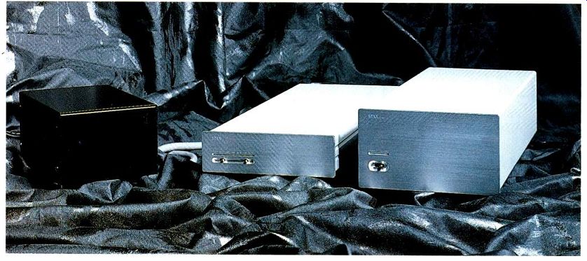
The system consists of three separate pieces: The ACD-1 a.c. line power supply, the BPS-Talent BD battery power-supply system, and the DAC-Talent BD D/A converter itself. The D/A converter's rear panel carries three selectable digital inputs: RCA phono coax, BNC coax, and EIAJ optical (Toslink). The unbalanced analog output jacks use the same high-quality jacks as the RCA digital input. A seven-pin connector receives power from the battery power sup ply's captive output cable; a similar cable on the line power supply feeds the battery supply. On the front panel of the D/A converter are two unmarked, horizontally oriented toggle switches under a seven-LED display. The left switch selects between the three digital inputs, with the LED indicators above showing the current choice ("Opt," "RCA," or "BNC"). Three more LEDs show which incoming sampling frequency is being decoded; the last LED shows when the analog output has been muted by pushing the second toggle switch to the right.
The interior area of the D/A converter is taken up by a double-sided p.c. board, which carries input-selection circuitry at its rear-panel end and most of the remaining circuitry up near the front panel. between these two circuit areas is a large space containing only a small plug-in daughterboard near the front of the board that holds the current-to-voltage analog output circuit. Another set of sockets near the rear of the board suggested that a much bigger daughterboard might be plugged in to accommodate a future upgrade. As it turns out, a large daughterboard, containing a different current-to-voltage section, was available, so I obtained one in order to try it out.
--------------
SPECS
D/A Conversion: Fixed, 20-bit.
Digital Filtration: 20-bit, with eight-times oversampling.
Sampling Frequencies, ±0.1%: 32, 44.1, and 48 kHz.
Frequency Response: 0 Hz to 20 kHz, ±0.5 dB.
THD + N at 1 kHz: 0.0015% at 0-dB signal level, 0.015% at-20 dB, and 1.5% at-60 dB.
S/N: 118 dB.
Dynamic Range: 104 dB.
Channel Separation: 120 dB.
Dimensions: 13 1/4 in. H x 5 3/8 in. W x 14 1/4 in. D (4.5 cm x 13.5 cm x 36.2 cm).
Weight: 2 lbs. (0.9 kg).
Price: $4,500.
Company Address: 16920 Halidale Ave., Gardena, Cal. 90247.
----------
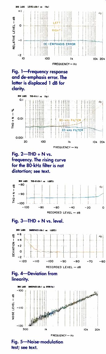
Fig. 1-Frequency response and de-emphasis error. The latter is displaced 1 dB for clarity.
Fig. 2-THD + N vs. frequency. The rising curve for the 80-kHz filter is not distortion; see text.
Fig. 3-THD + N vs. level.
Fig. 4-Deviation from linearity.
Fig. 5-Noise-modulation test; see text.
------------
As might be imagined, the battery supply box is largely (60%) filled with batteries-six 6-V, sealed lead-acid units, rated at 1.2 ampere-hours apiece. A motherboard in the remaining space mounts three plug-in boards that manage the charging and discharging (through powering the DAC) of the two sets of three batteries. A small piezoelectric device sounds when the battery charge gets low.
Of the three chassis pieces, the line power supply is the simplest and the least elegant in construction, having no front trim panel. Inside is an EI core power transformer whose primary and secondary windings are on separate halves of a split bobbin. A small p.c. board holds the a.c. line fuse, rectifier diodes, and the main filter capacitor (a 3,300-µF, 16-V electrolytic).
Circuitry
Each incoming coax signal is isolated by a transformer. Inverter logic gates amplify and square up the transformer-secondary signals that are applied to a signal-selector IC, as are similarly squared-up signals from the Toslink optical receiver. The selected output is routed to a surface- mount Yamaha YM3436C input dig ital receiver. The secondary phase-locked loop is contained on a small, potted daughterboard carrying surface-mount parts. (Because I had no schematic, this discussion is based on my examination of the units and is necessarily less complete than I would like.) A separate voltage-controlled oscillator for each in coming sampling frequency is indicated on the block diagram in the owner's manual.
Of interest here is the following digital low-pass filter (i.e., oversampler), which is the new NPC SM5842AP. The DAC Talent BD is one of the first components I've seen to use this filter. It has a wider, 32-bit accumulator, as op posed to the 25-bit accumulators in the somewhat more commonly used SM5803AP and SM5813AP digital filters.
THE STAX IS ISOLATED FROM THE A.C. LINE BY BATTERY POWER AND FROM JITTER BY DUAL PHASE-LOCK CIRCUITS.
The effect of having more accumulator bits is greater low-level accuracy in the filtering operation. In addition, the digital interface of this new filter allows data-word lengths of up to 24 bits. Output of the digital filter goes into the two Burr-Brown 1702 multi-bit DAC chips. Final analog output, in the case of the current-to-voltage (I-V) board originally supplied with the system, is via Analog Devices AD846 current-feedback op-amps used in the stage where the DAC's output current is converted to final audio output voltage. There does not appear to be a final anti-imaging low-pass filter in this design. The alternate I-V board is all discrete (no IC op-amps), in a circuit arrangement that I have no information about.
Measurements
Most of the measurements were done with the originally supplied, op-amp I-V board. Differences between the performance of this board and the alternate, discrete I-V board will be reported where they are significant.
Frequency response is shown in Fig. 1 for both channels without de-emphasis; response with the discrete I-V board was quite similar. Also shown (offset to-1 dB for clarity) is the right channel's deviation from perfect de-emphasis response (in other words, the de-emphasis error); left-channel de-emphasis error was essentially identical. Square-wave response (not shown) indicated the usual linear phase behavior and clipping of the ringing at digital full-scale when playing track 16 of the CBS CD-1 test disc; apparently, the new SM5842 digital low-pass filter is like its earlier relatives in this regard.
Figure 2 shows THD + N as a function of frequency at digital full-scale for 22- and 80-kHz settings of my measurement set up's low-pass filter. Usually, I display distortion versus frequency only for the 22-kHz measurement bandwidth. This time, however, I'm showing the 80-kHz results as well, to illustrate a phenomenon whose significance has just jelled for me. This phenomenon is common in D/A converters that use eight-times-oversampling digital filters without a low-pass filter following D/A conversion. What looks like increasing distortion at higher audio frequencies for the 80-kHz bandwidth is actually an in creasing amount of the 352.8-kHz over-sampling frequency and its harmonics, in the D/A process' stair-step approximation of reconstructed samples. As the signal frequency increases, the magnitude of the steps increases because there are fewer of them per period of the signal frequency.
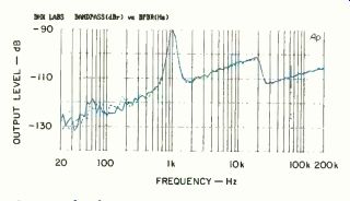
Fig. 6-Third-octave noise analysis; see text
(With measurement bandwidth opened up to 500 kHz, there is even more of this out-of-band energy.) It is not audio-frequency signal distortion per se, but its presence could possibly cause some distortion in the rest of the audio system due to slew-rate limiting, frequency beating, etc. in following equipment.
----------------
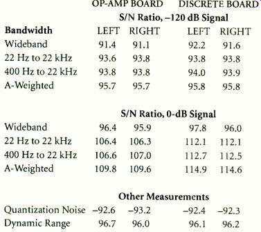
TABLE 1--S/N ratio, quantization noise, and dynamic range, in dB, with IC op-amp and discrete current-to-volt age boards; see text.
OP-AMP BOARD | DISCRETE BOARD
S/N Ratio,-120 dB
Signal Bandwidth
LEFT RIGHT LEFT RIGHT
Wideband
91.4 91.1 92.2 91.6 22 Hz to 22 kHz 93.6 93.8
93.8
93.8 400 Hz to 22 kHz 93.8
93.8 94.0 93.9
A-Weighted 95.7
95.7
95.8
95.8 S/N Ratio, 0 –dB
Signal Wideband
96.4 95.9 97.8 96.0 22 Hz to 22 kHz 106.4 106.3 112.1
112.1 400 Hz to 22 kHz 106.6 107.0 112.7 112.5
A-Weighted 109.8 109.6 114.9 114.6
Other Measurements
Quantization Noise
-92.6 -93.2 -92.4 -92.3
Dynamic Range
96.7 96.0 96.1 96.2
----------------------
Who knows-this may be partially responsible for some of the undesirable qualities often attributed to digital sound. The phenomenon is not unique to this converter, I am certain, and I will be reporting on it in subsequent reviews of D/A converters.
Figure 3 shows THD + N as a function of digital level at 1 kHz. The results are quite good here.
Input/output linearity at 1 kHz, plotted in Fig. 4 as a deviation from perfect linearity, is excellent. Figure 5 shows another test of low-level linearity, the noise-modulation test, devised by Richard Cabot of Audio Precision. A 40-Hz signal is set at amplitudes ranging, in 10-dB steps, from-60 to-100 dB relative to digital full-scale. The analyzer scans the range above 300 to 400 Hz with a swept third-octave filter. The curves should overlap, with any deviation indicating low-level nonlinearity. The results of the Stax for this test are excellent, as good as I've seen.
Interchannel crosstalk for both of the I-V boards was better than 110 dB down over most of the frequency range, even approaching that level at 20 kHz.
Test results for S/N, dynamic range, and quantization noise for both I-V boards are listed in Table 1. As can be seen, the new, discrete I-V board has e, and dynamic e current-to-volt-slightly better ultimate noise levels. In my test with an undithered, 1-kHz,-90 dB tone (not shown), the S/N of this converter with either I-V board was good enough to easily see the three-state (+1 LSB, 0, and-1 LSB) waveform. Figure 6 is a plot of noise in a third-octave bandwidth (with a dithered,-90 dB, 1-kHz signal). Results were the same whether the a.c. line cord was plugged in or not. Overall absolute polarity was correct, with a positive-going impulse resulting for a known positive-going digital input signal.
Use and Listening Tests
Digital signal sources on hand during the review period included Krell MD-10 and PS Audio Lambda CD transports, which fed the Stax system under review as well as a Sonic Frontiers SFD-2 and other, experimental, D/A converters. Analog source equipment (used for sonic reality checking) included an Oracle turntable fitted with a Well Tempered Arm and Spectral MCR-1 Select moving-coil pickup feeding a Vendetta Research SCP-2C phono preamp, Nakamichi's ST-7 FM tuner and 250 cassette recorder, and a Technics open-reel recorder. Preamps used were a First Sound Reference II, a Forssell tube line driver, and a Quicksilver Audio unit. Power amps used were a Crown Macro Reference, Quicksilver M-135s, and Arnoux MB300A and 7B digital switching units. Speakers were B & W 801 Matrix Series 3s, augmented by an experimental subwoofer using two JBL 1400Nd drivers.
Initial listening to the Stax D/A converter system was done by switching it through my Quicksilver preamp and out to whatever power amplifier I was using at the time.
The resultant sound was smooth and listenable. However, resolution, spatial replication, and overall musical believability were not of the order obtained with my present reference setup using the Sonic Frontiers SFD-2 with balanced outputs feeding a Forssell tube line driver modified for balanced input, and unbalanced output feeding the power amplifier.
I then decided to connect the Stax D/A converter's output directly into the Crown Macro Reference or into an Arnoux 7B switching amp, both of which have input level controls that allowed me to do with out a preamp. First up was the new I-V board: "Wow!" my listening notes say, "this really sounds quite good! Excellent sense of space and good definition and detail." Bass extension, punch, and tunefulness were exceedingly good-as good as or better than my reference setup. With the original IC op-amp I-V board reinstalled, sound was very similar to that with the discrete I-V board-but if I had to make a choice, I would opt for the discrete I-V board. As to overall sense of space and realism, though, the nod still goes to my reference setup by a narrow margin.
No operational glitches occurred in the use of the Stax D/A converter system. One evening, I had left it powered on without feeding a.c. to the charger, and my wife heard a weird sound emanating from the lab the next morning-the "battery-low" warning beep. In my system, with the a.c. cord plugged in and batteries charging, I left it on for long periods of time and had no problems doing so.
In conclusion, I think the Stax DAC-Talent BD D/A converter is a good piece, and I definitely enjoyed listening through it.
by Bascom H. King
Also see:
Stax SR-Lambda Professional Earspeaker System (Jan. 1985)
Stax Electrostatic Earspeakers (ad, Aug. 1984)
Link |