Manufacturer's Specifications:
FM Tuner Section:
Usable Sensitivity: Mono, 9.8 dBf.
50dB Quieting Sensitivity: Mono, 15.9 dBf; stereo, 36.8 dBf.
S/N: Mono, 83 dB; stereo, 78 dB.
THD: Mono, 0.06%; stereo, 0.08%.
Capture Ratio: 1.0 dB.
Alternate Channel Selectivity: 80 dB.
Image Rejection: 80 dB.
I.f. Rejection: 100 dB.
Spurious Response Rejection: 100 dB.
Stereo Separation: 55 dB at 1 kHz.
Output Level: 0.7 V for 100% modulation at 1 kHz.
AM Tuner Section:
Usable Sensitivity: 300 µV/meter.
S/N: 52 dB.
Image Rejection: 50 dB.
Selectivity: 40 dB.
Output Level: 0.2 V for 40% modulation at 400 Hz.
General Specifications:
Power Consumption: 120 V, 60 Hz.
Dimensions: 16.9 in. W x 2.0 in. H x 12.2 in. D (43 cm x 5 cm x 31 cm).
Weight: 8.6 lbs. (3.9 kg).
Price: $229.
Company Address: 1401 West Estes Ave., Elk Grove Village, Ill. 60007.
I tested two samples of the NEC T-6 tuner. The first one didn't work at all; the second, though it performed reason ably well in most respects, was slightly misaligned, possibly due to damage in shipping. (NEC normally ships equipment in batches, by truck; ours was a single-unit delivery via UPS.) My measurements and listening tests were conducted on that second sample, with no attempt to optimize its alignment. I am convinced that a carefully aligned unit would have been outstanding in every way, and that this model could be a real winner.
The electronic tuning system uses a digital phase-locked-loop frequency synthesizer controlled by a 4-bit microcomputer. The combination allows you to tune in stations manually, or automatically using the memory presets provided.
Up to seven AM and seven FM stations can be assigned to the presets.
A low-noise MOS-FET and 4-gang, twin-type varicap di odes are employed in the FM front-end section of the tuner.
The i.f. section consists of five stages of differential amplifiers and ceramic filters. A phase-locked-loop multiplex-de coder IC demodulates composite stereo signals. Ladder-type ceramic filters are used in the AM i.f. stages for wider-than-usual frequency response.
Control Layout
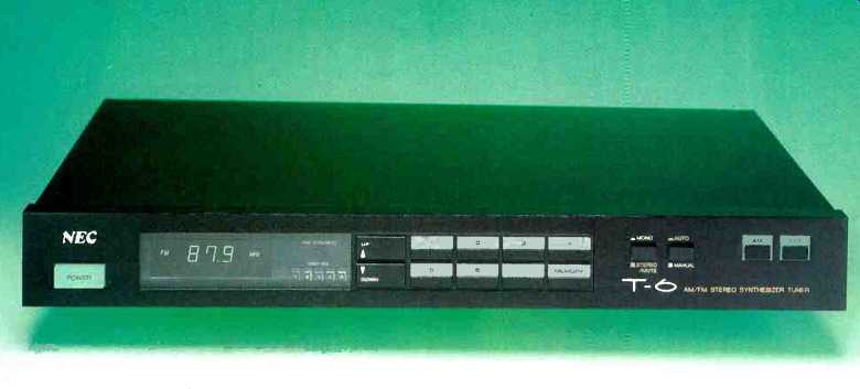
The very slim front panel, barely 2 inches high, nevertheless provides ample room for the few controls needed and for the visual displays which make the tuner so easy to use.
A rectangular "Power" button is at the lower left of the panel.
Nearby is a frequency display which changes in 200-kHz increments when tuned to FM and in 10-kHz increments on the AM band. An "FM Stereo" indicator light and a five-segment LED signal-strength indicator are positioned be tween the frequency display and the "Up" and "Down" tuning buttons. The seven numbered memory preset but tons and a "Memory" set button are near the center of the panel; to their right are a "Mono/Stereo/Mute" button, an "Auto/Manual" button, and the "AM" and "FM" band selector buttons. In the manual setting of the "Auto/Manual" pushbutton, one touch of the "Up" or "Down" button will change the tuned-to frequency, one step at a time. Holding either of these buttons down will advance tuning more rapidly. With the "Auto/Manual" switch set to "Auto," touching the "Up" or "Down" button will tune the T-6 to the next usable incoming signal on the dial.
The rear panel of the T-6 is equipped with an F-type coaxial connector for 75-ohm FM antenna cable connection; there are also screw-type 75-ohm, 300-ohm, and external AM and ground antenna terminals. An AM ferrite bar antenna at the center of the rear panel can be swung out and away from the chassis for best AM reception. The usual pair of left- and right-channel output jacks complete the rear-panel layout. There is no output level control.
Measurements
Although usable sensitivity of the T-6 was not quite as good as claimed, I was satisfied with the mono sensitivity reading of 11.0 dBf. Stereo usable sensitivity was limited by the muting threshold of the tuner since, in the stereo setting, low-level muting is always engaged. That muting threshold was set at 22 dBF, so signals of lesser intensity cannot be received in stereo by this tuner.
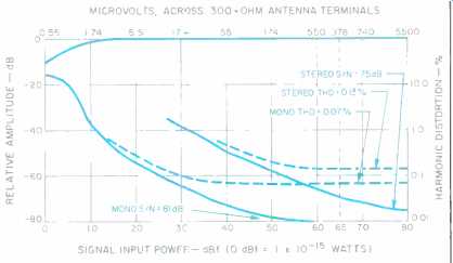
The 50-dB quieting point was reached with a signal input of 16 dBf in mono and a rather unimpressive 43 dBf in stereo. Best signal-to-noise ratio, with strong signal inputs, was 81 dB in mono and a respectably high 75 dB in stereo.
Quieting characteristics of the FM tuner section are shown in Fig. 1, along with plots of harmonic distortion as a function of input signal strength THD for mono reached a low of 0.07% with strong signals applied; in stereo, the THD measured 0.13%. Both readings were taken with a 4-kHz modulating signal.

Fig. 1--Mono and stereo FM quieting and distortion characteristics.

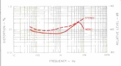
Fig. 2--THD vs. modulating frequency, FM section.
Figure 2 shows how harmonic distortion varies with modulating frequencies for both mono and stereo FM operation.
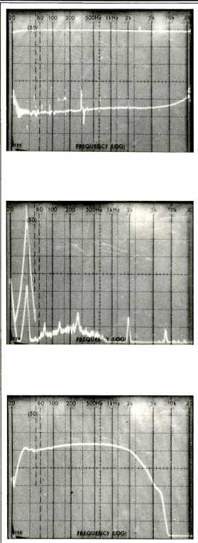
In mono and stereo, THD measured 0.1% at 100 Hz. At 6 kHz, mono THD was 0.23% and stereo THD measured 0.19%. Figure 3 shows FM frequency response and stereo separation over the audio range from 20 Hz to 20 kHz. (The frequency plots are logarithmic, and vertical sensitivity is 10 dB per division.) It was in making the separation measurements that I first suspected some misalignment of the tuner's stereo decoder section. With a signal modulating the left channel only, I read amazingly high separation figures in the right channel: 68 dB at 1 kHz, 59 dB at 100 Hz, and 56 dB at 10 kHz! Suspecting that something was amiss (these numbers are too good to be true), I switched things around so as to modulate only the right channel, while reading output from the left channel. Now, the separation figures were only 44 dB for the 1-kHz signal, 47 dB for the 100-Hz test tone, and 38 dB for the 10-kHz test tone. Certainly, these are not poor results by any means. In fact, they are the results shown in the 'scope photo of Fig. 3. They merely indicate that if the multiplex decoder section had been properly and symmetrically aligned, separation for either channel would have met the manufacturer's claim of 55 dB or better for a 1-kHz test tone. Left-to-right crosstalk would have been reduced somewhat, while right-to-left separation would have increased until it was approximately equal to left-to-right separation.

Fig. 3--Frequency response (upper trace) and separation vs. frequency, FM section
(see text).
Fig. 4--Analysis of 5-kHz distortion and crosstalk, FM section.
Fig. 5--Frequency response, AM section.
Figure 4 shows the results of my spectrum analysis of the distortion and crosstalk products that result when a 5-kHz signal modulates one channel of the FM signal. The tall spike at the left is the desired 5-kHz output; contained within it is the 5-kHz signal seen at .the unmodulated channel output. To the right are very small harmonic distortion components observed at the unmodulated channel output, as well as a couple of spurious but inaudible output components related to the 19-kHz pilot signal and the 38-kHz suppressed carrier signal. Also noticeable in this photo is a rising noise characteristic above 5 kHz; this may account for the tuner's inability to reach the ultimate S/N figure of 78 dB which the manufacturer claims for it in the stereo mode.
Capture ratio for the FM tuner section of this receiver measured 1.2 dB and alternate-channel selectivity was 82 dB, slightly higher than claimed. Image rejection measured 80 dB, exactly as claimed, while i.f. rejection measured 95 dB, falling somewhat short of the 100 dB claimed. Spurious response rejection measured better than the 100 dB claimed.
Figure 5 'is a spectrum analyzer plot of the AM tuner section's frequency response. Despite the rather elaborate AM circuitry used, AM frequency response did not extend much beyond the usual 2 to 3-kHz cutoff point typical of most AM/FM tuners and receivers.
Use and Listening Tests
I found the T-6 easy enough to use, though I must say that when I held down the "Up" and "Down" buttons for fast tuning, the tuning was so fast that it was almost impossible to stop or let go before passing the desired station frequency. The auto-scan tuning mode operated more to my liking, especially since the muting threshold, at about 22 dBf, was just high enough to eliminate stations that you wouldn't want to listen to, anyway, because of their background hiss. The NEC tuner was certainly sensitive enough for use in my suburban location and, hooked up to a decent outdoor directional FM antenna, it would more than likely be sensitive enough to serve fringe-area listeners as well.
My reservations about this tuner stem more from my having had to test two samples to get an almost-perfect one. I don't know whether the sets are being quality-con trolled only in their country of origin or whether at least some Q.C. sampling is taking place once they reach local NEC headquarters near Chicago. I've had some experience with NEC video products, all of which have' performed in an exemplary fashion. NEC can expect to be a similarly serious contender in the audio product sweepstakes if they can assure customers of equally high product performance.
-Leonard Feldman
(Source: Audio magazine, Dec. 1985)
Also see: NEC CD-650E Compact Disc Player (Dec. 1986)
Link | --NEC CD-803E Compact Disc Player (Nov. 1983)
Onkyo T-9090II FM Tuner (Jul. 1988)
Optonica ST-3636 AM/FM Stereo Tuner (Dec. 1978)
Pioneer Elite F-91 Tuner (Aug. 1988)
= = = =