Manufacturer's Specifications:
Preamplifier
Frequency Response: Phono, RIAA ±0.2 dB, 20 Hz to 20 kHz; high level, 5 Hz to 100 kHz, +0,-1 dB.
THD: Less than 0.015%, 20 Hz to 20 kHz, at rated output level, for any input or output.
S/N Ratio: MM phono, 82 dB A-weighted, 74 dB unweighted, re: 5 mV; MC phono, 76 dB A-weighted, 68 dB unweighted, re: 0.5 mV; high level, 100 dB A-weighted, 94 dB unweighted, re: 500 mV.
Input Sensitivity (For Rated Out put at 1 kHz): MM phono, 1.0 mV; MC phono, 100 µ,V; high level, 100 mV.
Input Overload Level (At 1 kHz): MM phono, 150 mV; MC phono, 15 mV; high level, infinite.
Input Impedance: Phono, 47 kilohms, user-selectable to any lower value; high level, 50 kilohms.
Output Impedance: 100 ohms.
Output Level: Rated, 1.0 V; maxi mum, 16 V.
Tone-Control Range: Bass, ± 8 dB at 100 Hz; treble, ±8 dB at 10 kHz.
Phase: With tone controls bypassed, noninverting from phono to main out, inverting from high level to main out, both reversed by switching tone-control circuits in; inverting from phono to tape out.
Dimensions: 16.5 in. W x 4.1 in. H x 11.2 in. D (42 cm x 10.5 cm x 28.5 cm).
Weight: 14.3 lbs. (6.5 kg).
Price: $1,495.
Power Amplifier
Power Output: 100 watts rms per channel continuous (120 watts IHF dynamic power), both channels driven into 8 ohms; 160 watts rms per channel continuous (200 watts IHF dynamic power), both channels driven into 4 ohms.
Power Bandwidth: 10 Hz to 50 kHz.
Rated THD: Less than 0.05%, 20 Hz to 20 kHz, at or below rated output.
Frequency Response: 5 Hz to 60 kHz, +0,- 1 dB;-3 dB at 120 kHz.
S/N Ratio: 110 dB, A-weighted, be low rated output.
Rise-Time: 2.5 µS at rated power.
Channel Separation: 70 dB, 20 Hz to 20 kHz.
Input Sensitivity: 1.0 V rms for rated output.
Input Impedance: 50 kilohms.
Output Impedance: 0.05 ohm.
Phase: Noninverting.
Dimensions: 16.5 in. W x 4.1 in. H x 11.6 in. D (42 cm x 10.5 cm x 29.5 cm).
Weight: 28.6 lbs. (13 kg).
Price: $1,195.
Company Address: c/o AudioQuest, 629 Camino de Los Mares, #306, San Clemente, Cal. 92672.
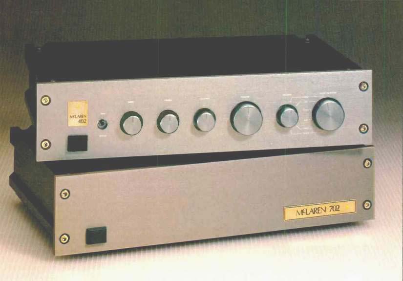
The McLaren 402 stereo preamp and 702 power amplifier are very attractive, nicely made pieces of audio gear from New Zealand. I heard the 402 preamp and a pair of the 902 mono power amps driving a pair of Vandersteen speakers at the '86 Winter CES and was favorably impressed with the sound. As it turned out, Audio had the 402 and 702 slated for review, and they turned up on my doorstep a month or so after the show.
Construction
Both units are built up from two thick aluminum-extrusion sides bolted to the front panels. The rear panels and bottom plates bolt to the extrusions. The top covers slide from the rear into slots in the extrusions and are held in place by four Allen-head bolts. In both units, the top covers are mounted so as to allow an air space about a quarter of an inch high by 14 inches wide; this allows internal heat to escape out the rear.
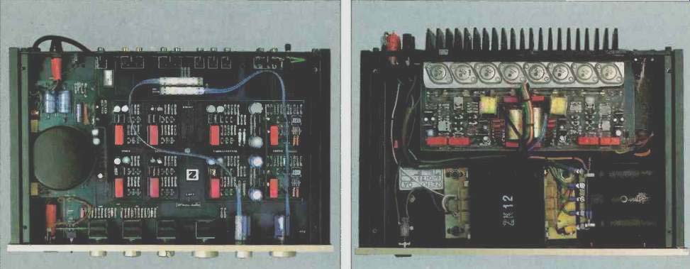
The power amp's rear panel is a thick aluminum casting with vertical fins over most of its outside surface. Two pairs of five-way speaker binding posts, a pair of female RCA input jacks, a line fuse, and a power cord are on this panel.
A horizontal ledge on the inside of the rear-panel casting has four pairs of Hitachi power MOS-FETs in TO-3 metal cases mounted on it. A p.c. board extending under the ledge picks up the power-transistor pin connections and carries the rest of the amplifier circuitry. A pair of 15,000-µF, 63-V main filter capacitors are mounted on their sides near the right front of the amplifier. A bus bar connects the ground sides together and serves as a means to connect the various circuit grounds to this point. A good sized El-lamination power transformer is mounted to the amp's bottom plate at front center. On the front panel are a pushbutton power switch and a yellow LED to indicate when power is turned on.
The preamp has a large p.c. board that takes up the whole interior of the unit. A potted toroidal power transformer and the other power-supply components are located along the left side of this board. Tone, balance, and volume control potentiometers are sealed Alps dual units which mount to the front of the p.c. board. The tape source and main selector knobs operate rotary-to-linear converter mechanisms that control, via a flat metal cab e, remotely located slide switches at the rear of the board near the signal input jacks. The preamp's active signal circuitry takes up the remainder of the board space. Of note here is the use of a "star grounding" scheme whereby all signal grounds come from various points in the circuitry to one common point. Signal in/out jacks are gold-plated p.c.-mount types.
The preamp's front-panel controls, from left to right, are a pushbutton power switch; a tone-control bypass toggle switch; and rotary knobs for bass, treble, balance, volume, record-out selection, and main input selection. A yellow power-on LED is located above the power switch. On the rear panel are the signal input and output jacks, power cord, line fuse, and a ground terminal post.
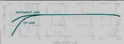
Fig. 1--Line-level frequency response, 402 preamplifier, for reviewer's
instrument load (see text) and for standard IHF load.
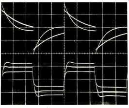
Fig. 2--Square-wave response, 402 preamp line-amplifier section.
Upper traces are for 20-Hz signal, with instrument load and (showing greater tilt) with IHF load. Lower traces are for 20 kHz, right channel, with balance control set full right (largest trace), centered, and set full left (smallest trace). Scales: Vertical, 2 V/div.; horizontal, 10 mS/div. (upper traces), 10 µS/div. (lower traces).
Preamplifier Circuitry
The 402 preamp consists of four active circuit blocks per channel: A phono input stage, phono equalizer, output or line amplifier, and tone-control amplifier. All of these blocks have essentially the same circuit topology-complementary dual-differential input amplifiers driving complementary common-emitter output stages whose collectors are tied at the output point. All have direct-coupled inputs and capacitor-coupled outputs. Emitter degeneration (negative feed back) is not used in the input stages but is used in the output stages.
The input-stage emitter pairs are fed via a simple resistor tied to the appropriate supply rail. All devices are bipolar.
Each block has its own three-terminal plus-and-minus regulator. The phono input stage operates the differential amps at 5 mA per device and has a switchable feedback loop for two closed-loop gains: 21.5 dB for moving-magnet cartridges and 43.3 dB for moving-coil. Frequency response is flat in this stage. The shunt feedback resistor in the moving-coil feedback divider is 4.7 ohms for lowest noise in this mode. There are two 4PST DIP switches on the p.c. board, one for each channel, to control the mode of the phono input stage. Two poles select the feedback divider, a third puts 1,000 pF across the phono input in moving-coil mode, and the fourth pole selects 100 ohms or 47 kilohms for phono input resistive loading. The phase of the phono input stage is noninverting. Output coupling to the phono equalizer is via a 1-uF polypropylene capacitor. The equalizer stage is configured as an inverting amplifier. The input resistor is split into two parts with a capacitor to ground at the junction of the two resistors. This forms a passive roll-off at 2,120 Hz for the high-frequency equalization. The feedback network contains an RC network to accomplish the bass boost between 50 and 500 Hz. A consequence of this phono topology is that absolute phase is inverted at the tape output for a correctly connected phono cartridge.
The main and tape-out selector switches in the 402 are functionally very effective. All high-level inputs, including both tape inputs and the output of the phono equalizer, go to the contacts of both switches. The wipers of the tape selector go to tape out, and the wipers of the input selector go off to the volume controls feeding the output amplifiers.
This arrangement allows one to record and listen to each input source independently.
The line amplifier is different from most such circuits in that it is connected in the inverting mode instead of the more usual noninverting connection. The output of the volume control, which is 50 kilohms, drives the input summing resistor, which has a value of 12 kilohms. This causes the high-level input impedance or the load on the phono equalizer to drop down to only about 10 kilohms when the volume control is fully up. This is not a likely occurrence in normal use, but it can arise. For example, I ran into this condition when using a 0.5-mV moving-coil cartridge in the moving-magnet phono mode. I had to set the volume control close to maximum to get the listening levels desired.
The balance function is accomplished by altering the feedback resistors in the line amplifier in a complementary manner with the balance-control dual potentiometer. When the balance control is centered, gain is set at about 21 dB by the ratio of the feedback resistors to the input resistors.
The balance control alters the gain of each channel by ±3 dB for a total channel difference of 6 dB.
The tone-control amplifier, the last active block in the chain, is always driven by the output of the line amp. The circuit is inverting, using the usual Baxandall tone-control topology with a gain of-1. The main output jacks are connected to the wipers of a DPDT toggle switch that selects either the main output of the line amp or the output of the tone-control amp.
Since the phono output is inverting and the line amp is inverting, the overall phase from phono input to main out is noninverting. However, high-level inputs to main output are inverting but can be rendered noninverting (at the expense of adding the tone amp) by engaging the tone-control switch. The only thing one can't correct is the inverting phase of the phono input to tape out. High-level inputs to tape out are, of course, noninverting, as there are no active electronics in this path.
The power-supply circuitry of the 402 preamp starts out with full-wave-rectified ±34 V d.c. filtered by two 1,000-pc/ 50-V capacitors. This rectified and filtered d.c. is regulated down to ±27 V d.c. by 24-V, three-terminal regulators with their reference terminals going to ground through 3-V zener diodes. The regulator outputs are bypassed by 100-µF electrolytics and 0.1-µF film capacitors. The first stage of the phono preamp is regulated down to ± 11 V by a zener follower arrangement.

Fig. 3--RIAA equalization error for 402 preamp's MM and MC inputs, with
instrument and IHF loads. Note the low-end roll-off and the expanded scale.
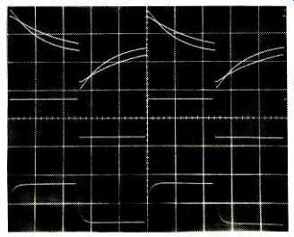
Fig. 4--MM phono response, 402 preamp, to pre-equalized square waves at
40 Hz (top traces), 1 kHz (middle trace), and 10 kHz (bottom trace). Note
effects of IHF (greater tilt) and instrument loads at 40 Hz. Scales: Vertical,
2 V/div.; horizontal, 5 mS/div. (top), 200 RS/div. (middle), 20 uS/div. (bottom).
Fig. 5-THD + N vs. frequency, 702 amplifier, for power levels of 1, 10, and 100 watts into 8 ohms (solid curves) and 3, 30, and 120 watts into 4 ohms (dashed curves).
Fig. 6-Harmonic distortion residue, 702 amp, for two frequencies, at 10 watts output into 8-ohm loads.
Upper traces show 0.008% THD at 1 kHz; lower traces show 0.025% THD at 10 kHz. Note similarity between distortion waveforms (see text).
Power Amplifier Circuitry
The 702 power amplifier's circuitry is fairly simple and straightforward; it consists of a two-stage differential amplifier with a turn-around circuit in the second stage, driving two pairs of complementary MOS-FET power devices in parallel.
All front-end transistors are bipolar. The signal input to the input differential amp is capacitor-coupled by a 1-µF poly propylene capacitor loaded with 47 kilohms to ground, followed by a 2.2-kilohm series resistor and a 330-pF capacitor to ground at the noninverting base. The input de vices are PNP, with an overall d.c. output offset-adjustment pot in their emitter circuit. Collector outputs of the first stage are direct-coupled to the bases of the second differential stage, which utilizes NPN devices. One collector output is part of the composite drive to the output stage; it is connected to the bottom of the bias-spreading resistor and drives the gates of the P-channel output devices. The other output collector goes up to the base of a PNP device which has a diode in series with 100 ohms up to a positive power supply.
The emitter of this transistor also goes, through 100 ohms, to the same positive supply. The collector goes down to the positive end of the bias-spreading resistor and drives the gates of the N-channel output MOS-FETs. The function of the aforementioned turn-around transistor is to take one of the differential output phases of the NPN differential pair, invert that phase, aid add the resultant output to the other phase to develop a complementary signal based to ground; this drives the output stage. The output resistance of this drive stage is fairly high. Most designs that use MOS-FET output devices use an additional complementary emitter-follower stage to more effectively drive the considerable capacitance that MSS-FETs have at high frequencies. On the other hand, the 702 has one less stage and may be sonically the better for it.
Overall negative feedback is taken from the output to the inverting input of the input differential amp via a series resistor bypassed by a small capacitor. The shunt feedback resistor is returned to ground through a 220-uF capacitor bypassed by a 1-µF polypropylene film capacitor. Thus, the d.c. gain of the circuit is 1, with an input roll-off of about 3 to 4 Hz and a second roll-off, in the feedback network, of about 0.9 Hz.
A full-wave bridge-rectified supply provides ±53 V d.c. for both output stages. A separate half-wave-rectified sup ply provides power for two positive regulators and one negative regulator for each channel to feed the front-end circuitry with one negative and two positive voltages. These voltages are higher than the output-stage potentials to en sure full drive to the MOS-FETs.
Preamplifier Measurements
Line-amp gain of the McLaren 402 was found to be about 10.75 x or 20.6 dB. This yields an IHF sensitivity for AUX inputs of some 46.5 mV. Output impedance of the line amp was a low 36 ohms in series with 1 µF. With the tone stage switched in, output impedance was found to be lower yet (due to more feedback from its -1 gain), about 5 ohms in series with 1 µF.
THD + N at 10 V rms output was less than 0.01% from 20 Hz to 20 kHz for my instrument load (91 kilohms in parallel with 250 pF) or the IHF load of 10 kilohms in parallel with 1,000 pF. This was true whether the tone stage was switched in or not. Clipping level was some 16 V rms. The line amp would drive 600 ohms to 10 V rms at about 0.3% distortion, although the 3-dB low-frequency cutoff point was around 260 Hz due to the 1-1.11 output coupling capacitor.
Frequency response for the line section is shown in Fig. 1.
The low-frequency roll-offs are due to the 1-uF output coupling capacitors.
Channel-to-channel crosstalk was measured using the "CD" high-level input, with the volume control fully on and the undriven input terminated by 1 kilohm. Results differed slightly, depending- on which channel was driven. For the worse direction, R to L (drive right, measure left), crosstalk was better than -80 dB up to 10 kHz, increasing to -78.8 dB at 20 kHz and -66.7 dB at 50 kHz. With the tone stage engaged, crosstalk increased to -70.8 dB at 20 kHz and -61.4 dB at 50 kHz--very good figures. The crosstalk signals were in phase for pulse or square-wave excitation.
Volume-control tracking was found to be within ±0.2 dB down to-45 dB, ±0.5 dB to-60 dB, and almost 3 dB out at -70 dB.
Rise- and fall-time for the line amp, with or without the tone amp engaged and with instrument or IHF loading, was 1.8 RS up to ±20 V output. Further, it was about the same with the volume control down 6 dB from maximum. This is good performance. The right channel had about 6% over shoot, probably due to the tolerance of the small capacitors across the feedback resistors in the line-amp circuit. 'Scope photos of the line section's square-wave performance are shown in Fig. 2. The top traces are for a 20-Hz signal for instrument and for IHF loading; the greater tilt is for the IHF loading. The bottom traces are for a 20-kHz signal through the right channel, with the balance control fully clockwise, centered, and fully counterclockwise. The highest amplitude trace is for the clockwise (maximum right) position.
Phono preamp gain in the moving-magnet mode turned out to be 101 x or 40.1 dB at 1 kHz. I ran into erratic results when attempting to measure MC gain by feeding both input channels in parallel from a common source, my usual method. Further investigation revealed a tendency for the preamp to oscillate at about 10 MHz when the inputs were paralleled physically close to the jacks in MC mode. With one input driven at a time, gain was stable enough to be measurable. This instability under measurement conditions also prevented reliable assessment of input noise in the MC mode with low-value terminating resistors plugged directly into the input jacks. All of this seems to be a peculiarity that the 402 displays only under measurement conditions-I had no problem using the unit in several audio systems. The majority of cartridges, with no external tie points between their signal grounds, would act as separate signal sources of each channel; therefore, the problem would not occur.
When finally measured, moving-coil gain turned out to be 60 dB at 1 kHz. Phono sensitivity (IHF) measured 5 mV for MM and 500 ILV for MC from phono to tape out, and 465 µV for MM and 46.5 µV for MC from phono to main out.
Phono noise in MM mode is summarized in Tables IA and IB. MM input noise in the band from 400 Hz to 20 kHz appeared to be about 100 nV. In use, the subjective noise in MC mode was about 10 to 12 dB quieter than in MM mode.
Phono overload versus frequency and loading is summarized in Tables IIA and IIB. One thing is of note here: Up to about 10 kHz, the output waveform indicated overload by distorting one or both peaks in some way. Above 10 kHz, the input acceptance should about double, theoretically, but does not in this design. Looking at the THD residue while doing this test, peak aberration turns into a symmetrical compression above 10 kHz, indicating that the first-stage block of the phono preamp circuit is probably clip ping. Still, 152 mV at 1 kHz for MM is a good, respectable figure. Large-signal response to a pre-equalized, non-band-
limited square wave into the phono section was good up to about ±2 V. Above this output level, the waveform started to symmetrically compress the high frequencies.
Source
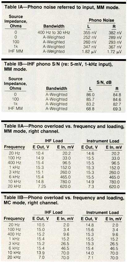
Table IA-Phono noise referred to input, MM mode.
Table IB-IHF phono S/N (re: 5-mV, 1-kHz input), MM mode.
Table IIA-Phono overload vs. frequency and loading, MM mode, right channel.
Table IIB-Phono overload vs. frequency and loading, MC mode, right channel.
Phono equalization error for MC and MM modes, measured at tape out, is shown in Fig. 3. Of interest is the very noticeable roll-off in the low end, especially with the IHF load. For some reason that I don't understand, the low-end roll-off is worse for MM than for MC. One thing to remember in this design is that the more clockwise the volume control is, the lower the load impedance that the volume control/line amplifier will present to the phono output, the limit being about the 10 kilohms of the IHF load. I don't care for this measured characteristic in the 402, as I believe that the lower the low-frequency response--all other factors remaining the same--the better the overall sound.
The phono section's square-wave response in MM mode is shown in Fig. 4. The top traces are a 40-Hz signal, shown with instrument and with IHF loading, the latter having the greater tilt. The middle (1-kHz) and bottom (10-kHz) traces look the same with IHF or instrument loading.
Finally, MM phono channel-to-channel crosstalk was measured with the undriven channel terminated by 100 ohms. Results were extraordinary--greater than 80 dB down, from 20 Hz to 50 kHz, in both directions. With the undriven channel terminated by the IHF MM load, crosstalk was absolutely symmetrical (a first) in both directions, rising to -60.6 dB at 5 kHz and peaking at -50 dB at 9 to 10 kHz.
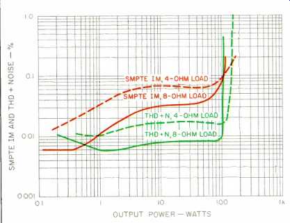
Fig. 7--Distortion vs. frequency, 702 amp, showing THD + N at 1 kHz, and
SMPTE IM, for 8- and 4-ohm loads.

Fig. 8--Frequency response, 702 amp, with no load (open circuit) and with
8- and 4-ohm loads.
Power Amplifier Measurements
The 702 power amp was run at one-third power (33.3 watts) into 8-ohm loads for one hour. The heat-sinks got very hot during this interval. Since I could not find any indication of a thermal cutout in the schematic, I decided not to run the test into 4-ohm loads.
Voltage gain was found to be 33.5 x or 30.5 dB, which yields an IHF sensitivity of 84.4 mV to produce 1 watt into 8 ohms. The manufacturer's spec for input sensitivity is 1 V to produce rated output; in view of the measured gain, input sensitivity for rated output is more like 0.84 V.
THD + N as a function of power, frequency, and load is shown in Fig. 5. Typical harmonic-distortion residue is shown in Fig. 6 for 10-watt outputs at 1 and 10 kHz. Sensitivity for distortion is the same in both 'scope traces. I measured 1-kHz distortion as 0.008% and 10-kHz distortion as 0.025%. What is interesting is that the wave shape is very similar for the two frequencies. The magnitude increase at 10 kHz is probably due to lower loop gain (less feedback) at higher frequencies. There are no stability-compensation capacitors per se in the circuit except the small one across the feedback resistor. Therefore, I deduce that the reduction in loop gain at higher frequencies is most likely due to the high drive impedance to the MOS-FET output transistors against their input capacity. Figure 7 shows 1-kHz distortion versus power and load, along with SMPTE-IM distortion.
Dynamic power was found to be 121 watts into 8 ohms and 210 watts into 4 ohms. Steady-state clipping power was 105 watts into 8 ohms and 160 watts into 4 ohms. All tests were done, as usual, with 120-V a.c. line power.
Frequency response, at a 1-watt level into 8 ohms (2.83 V rms), is shown in Fig. 8 for no load (open circuit), 8-ohm loading, and 4-ohm loading. 'Scope photos of square-wave behavior appear in Fig. 9. The top traces are for a 10-kHz signal with no load and with loads of 8 and 4 ohms. The middle trace is for 10 kHz loaded with 8 ohms in parallel with 2 uF. The bottom trace is for 40 Hz with an 8-ohm load. The output buffering inductor in this design seems to have more inductance than usual, as evidenced by the top traces in Fig. 9, where the effect of output loading at the higher frequencies extends more into the half-cycle time of the 10-kHz signal. However, the low ringing on the 8-ohm, 2-uLF load is exemplary. Rise- and fall-time into 8 ohms was 2.8 uS at ±5 V output. Large-signal rise- and fall-time in creased to 3µS, with some overshoot on the positive-going transition only. Clipping behavior at high frequencies showed considerable evidence of "sticking." Crosstalk versus frequency was measured with the undriven channel terminated in 1 kilohm. The crosstalk was some 6 to 8 dB worse in the right-to-left direction and still measured better than -80 dB at 1 kHz, rising to-69 dB at 5 kHz, -56.7 dB at 20 kHz, and -49.5 dB at 50 kHz.
Signal-to-noise ratio (IHF) for the 702 amp was 95.3 dB for the right channel and 93.8 dB for the left. Damping factor versus frequency is shown in Fig. 10.
Regarding peak current delivery: I have been using, at different times, 0.1- and 1-ohm loading for this test. It is obvious that 1 ohm is a more realistic load to use, as some speakers have been known to dip down to nearly 1 ohm but certainly not to 0.1 ohm. Accordingly, I have decided to use 1 ohm for this test from now on. The 702 was able to deliver a respectable ±2c amps into 1 ohm with one channel driven using the IHF 1-kHz tone-burst signal.
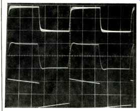
Fig. 9--Square-wave response, 702 amp. Top traces: 10 kHz into 8- and 4-ohm
resistive loads and into open circuit (no load). Middle trace: 10 kHz into
8 ohm, 2-µF load. Bottom trace: 40 Hz into 8-ohm load. Scales: Vertical,
5 V/div.; horizontal, 20 µS/div. for 10-kHz traces, 5 mS/div. for 40-Hz trace.
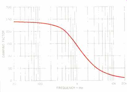
Fig. 10--Damping factor vs. frequency, right channel, 702 amp.
Use and Listening Tests
Equipment used in my system to evaluate the 402 and 702 included an Infinity air-bearing turntable and arm with a Koetsu EMC-1B cartridge and Infinity RS IIB speakers. Other electronics on hand were Robertson Twenty Twenty and Cook/King reference preamplifiers and Marantz Nine power amplifiers.
My first reaction to the McLaren components was that the preamp was pretty good and the amp wasn't so good.
However, after both pieces had warmed up by being left on for a couple of days, I found myself commenting, "This equipment makes pretty good music after all." I would definitely recommend leaving these pieces on continuously; otherwise, one will never hear them at their best. I found that the sound of the preamp was noticeably better in the MM mode using my 0.5-mV Koetsu than in the MC mode, considerations of noise, and of bass roll-off with volume control at max, aside. No operational glitches were observed in use with either piece, separately or in combination with other components. Subjectively, I didn't like the tone-control characteristics because the turnover frequencies seemed to be too low for the bass and too high for the treble.
The importer of the McLaren equipment informed me of a modification to the power amp that has improved its sound and is representative of current production. This consists of bypassing the four internal power-supply fuses with 0.01-µF Wonder Caps. After receiving and installing these capacitors, I warmed up the amp again and found that, indeed, the sound was better. I have listened to these units for hours on end without irritation and have been fairly satisfied with their presentation.
I tried the preamp in a friend's system which includes Snell Type A-Ill speakers, a conrad-johnson PV5 preamp, a Robertson Forty Ten amp for bass, and Gordon Mercer feedback-less tube amps for mid/highs. The sound was very good and musical with the McLaren preamp in this system. It was interesting to find that when an Infinity hybrid Class-A power amp was substituted for the Gordon Mercer tube amps for mid/highs, the system also sounded very good, and similar to the sound with the tube amps. However, when the conrad-johnson PV5 preamp was reinstalled in place of the McLaren, the sound wasn't so hot with the Infinity amp, but was good again with the tube amps-one of the many combinational puzzles I've encountered.
The 702 power amp was tried in the system of my associate Geoff Cook, where we used it as a bass amp up to 300 Hz along with a Crown Microtech 1000 and a Robertson Sixty Ten. The McLaren 702 was judged to be the best in this application by a considerable margin.
In my system, I have used the 402 preamp with Marantz Nine power amplifiers and have obtained very good results.
Even better results come from using the 702 power amp with the Cook/King reference tube preamp; this is what makes me suspect that the power amp has better sound than the preamp. Sound with the combination of 702 and Cook/King is extremely smooth and spacious, with a harmonic "rightness" that continues to amaze me.
In conclusion, I would have to say that I like these pieces of McLaren gear quite a lot and would recommend a serious listen.
-Bascom H. King
(Source: Audio magazine, Dec. 1986)
Also see: Link |
Threshold SA/4e Power Amp (Jan. 1991)
McIntosh Model C-27 Stereo Preamplifier (Sept. 1978)
= = = =