Electrical energy entering free space does so in the form of electromagnetic waves. It travels at the velocity of light, a speed of 3 x 10^8 meters per second. Collectively, such energy is called a radio wave. A radio wave consists of both magnetic and electric fields that are at right angles to one another and also at right angles to the direction they travel. If these waves are generated by an alternating current, they will vary in intensity and swing both positive and negative as they alternate throughout each cycle. The wavelength of each cycle (lambda), then, is equal to the free-space velocity (rate of travel) divided by the number of cycles transmitted each second:
Wavelength (λ) = 300,000,000 M / f frequency
All operating electrical circuits radiate to some degree. A power line, for example, with relatively short footage spacing between conductors will radiate very little if it is in good working order, since a wavelength at 60 Hz is over 3,000 miles-a huge difference by comparison. But a large transmitter with 50,000 watts output will propagate enormous energy since it uses a large radiator with a length inversely proportional to frequency. Therefore, high-frequency waves may be broadcast over considerable distances by medium and large-size radiators. The limiting factor in very high frequency transmissions, such as TV, is called the "line of sight." Such transmissions are not affected by the ionosphere, and so will go directly off into outer space at the horizon-a characteristic that has been made good use of in many forms of aircraft and satellite communications, as well as microwave.
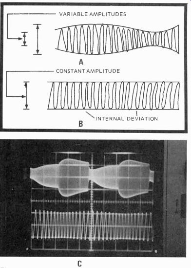
Fig. 1-1. Drawing of an amplitude (AM) modulated waveform, where the envelope amplitude is varied by "contraction" and "expansion" (A). Frequency modulated waveform (FM) showing carrier frequency deviation but not amplitude variation (B). Scope waveforms showing 400-Hz AM modulation (top) of a nonlinear sine-wave generator operating at 12.5 MHz. FM modulation (bottom) is represented by a 1.6-MHz carrier modulated by a 100-kHz signal.
For a transmitted wave to contain intelligence, some part of it must be varied (modulated) in time and degree (frequency deviation or amplitude) by the information you wish it to carry. In radio broadcasts, this variation is achieved either by amplitude (AM) or frequency modulation (FM). And in television transmissions, the sound and picture intelligence is dispatched by both FM (sound) and AM (picture). Also, because of the various pulses for vertical and horizontal picture synchronization (sync) and another pulse for color synchronization we almost have phase and pulse modulation in addition. So in color television, many of today's electronic marvels are collected into a single unit.
AMPLITUDE (AM) and FREQUENCY (FM) MODULATION
The beginning of almost all signals at RF frequencies is a sine-wave (an alternating wave) generator that oscillates at the mean (middle) frequency of any designated RF band. The generated wave is called a carrier, and what is done with this carrier determines the information that it will transport from some point of origination to another point of reception.
In amplitude modulation, for instance (Fig. 1-1A), the entire envelope of the carrier amplitude is "expanded" or compressed by the frequency and variation (with time) of another wave representing sound, picture, etc. If such a modulating signal had a 1-kHz (1,000) frequency, the higher frequency carrier would be subjected to 1,000 amplitude variations each second.
In frequency modulation (Fig. 1-1B), the carrier amplitude remains constant while the carrier frequency itself is varied (contracted and expanded) according to both the intensity (magnitude) of the modulating signal and its rate (time). Therefore, if the same 1-kHz signal modulated a 1,000-kHz sine wave carrier, the deviation could range from 1,000.1 kHz to 999.9 kHz on small output signals to 1,010 and 990 kHz on large signals. This analysis immediately suggests there could be a number of sine waves modulating a carrier with pairs of frequencies surrounding the carrier frequency. And this is true, since, for every frequency apparent in any modulating wave, there are two immediate side frequencies generated, one above and the other below the main carrier. These are called the upper and lower sidebands and are especially important in the study of color television.
THE NTSC COLOR SYSTEM
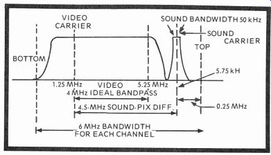
Fig. 1-2. Drawing of the 6-MHz bandpass response for all VHF-UHF TV channels
showing the 4.5-MHz difference between sound and picture carriers and an ideal
video bandpass of 4 MHz, something that's not realized with color.
As with monochrome, the allowable frequencies for the VHF channels begin with 54 MHz for Channel 2 through 88 MHz for Channel 6. There's then a skip from 88 to 180 MHz for the FM-stereo band, and from 108 to 174 MHz for other types of services. Channel 7 begins at 174 MHz and the TV spectrum continues through Channel 13 at 216 MHz. UHF stations start with Channel 14 at 470 MHz and end on Channel 83 at 890 MHz, a total of 70 UHF spaces in the spectrum.
Each VHF-UHF channel has a bandpass (bandwidth) of 6 MHz (Fig. 1-2), with the video carrier 1.2 MHz higher than the lowest frequency specified for an individual channel, and the 50-kHz wide sound carrier positioned 0.25 MHz from the top of the channel, thus separating audio and video by 4.5 MHz. For that reason, you can determine tuner response easily with a sweep generator, a video carrier marker, and a 4.5-MHz marker ( for sound). As you'll see later, you can determine both tuner bandwidth and waveform rolloff or symmetry by the position of the markers. The lower sideband width is limited to 1.25 MHz to prevent interference with an adjacent channel, but the upper sideband extends a full 4.25 MHz above the picture carrier.
Constriction of the lower sideband to 1.25 MHz is called vestigial sideband transmission and helps keep the overall channel passband within the allotted 6 MHz. The transmission is made possible by a carefully designed, fairly sharp rolloff filter that attenuates but is accurate within the limits of the carrier frequency because its edge coincides with the carrier frequency. Fig. 1-3 shows this lower sideband attenuation and also puts the picture carrier in immediate perspective.
In Fig. 1-3 the I and Q color sideband signals have been added, plus the color subcarrier frequency of 3.579,545 MHz the carrier for all color information. The I and Q sidebands have the phase relationship to burst signals shown in Fig. 1-4.
The burst is nothing more than the color sync signal, and is simply a sample of the original 3.58-MHz subcarrier inverted 180 degrees. From Fig. 1-3, you can see that color information is contained in the I and Q sidebands on either side of the single subcarrier.
I and Q information modulates the 3.58-MHz subcarrier, with I and Q signals each allotted a double sideband position on either side of the carrier from 0 to 0.5 MHz about the carrier. Single sideband transmission also exists from 0.5 to 1.5 MHz. This prevents crosstalk interference between the two color signals when received. We won't talk extensively about the I and Q color intelligence at the moment, but Fig. 1-5 should help explain what is meant now. However, you should understand that the I sidebands produce colors from bluish-green to orange, and purple (magenta). They both, obviously-and this is highly important-have green components, as does the luminance Y signal, and this characteristic can be used to advantage both in transmission and reception as you will soon see.
FILTER 3.579,545 MHz COLOR SUBCARRIER PICTURE CARRIER (AM)
-1.25 MHz 4.5 MHz 6 MHz PASSBAND SOUND CARRIER (FM)
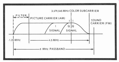
Fig. 1-3. The same monochrome characteristics in Fig. 1-2 are indicated here,
but with color information now added.
The drawing also shows the effect of a filter for negative vestigial sideband compression. Notice I and Q signals on either side of color subcarrier, plus the color sync sub-carrier.
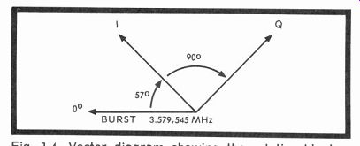
Fig. 1-4. Vector diagram showing the relationship between burst (3.579,545-MHz
subcarrier) and the I and Q sidebands.
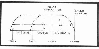
Fig. 1-5. Color I and Q double sidebands are shown on either side of color
subcarrier at 0.5-MHz frequencies, with I extending to 1.5 MHz in the single
sideband (to the left). The sound carrier is at upper right of diagram.
========
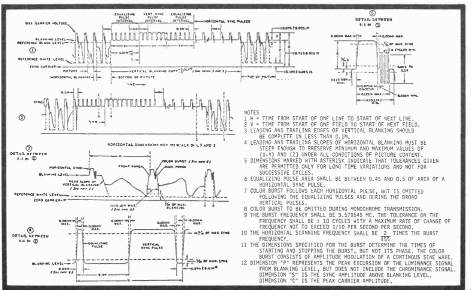
Fig. 1-6. Drawing showing the standard U.S. color TV sync signals transmitted
and received only during vertical and horizontal blanking periods when there
is no picture.
NOTES
1 H-TIME FROM START OF ONE LINE TO START OF NEXT LINE.
2 V-TIME FROM START OF ONE FIELD TO START OF NEXT FIELD.
3 LEADING AND TRAILING EDGES OF VERTICAL BLANKING SHOULD BE COMPLETE IN LESS THAN 0.1M.
4 LEADING AND TRAILING SLOPES OF HORIZONTAL BLANKING MUST BE STEEP ENOUGH TO PRESERVE MINIMUM AND MAXIMUM VALUES OF (X-Y) AND (Z) UNDER ALL CONDITIONS OF PICTURE CONTENT.
5 DIMENSIONS MARKED WITH ASTERISK INDICATE THAT TOLERANCES GIVEN ARE PERMITTED ONLY FOR LONG TIME VARIATIONS AND NOT FOR SUCCESSIVE CYCLES.
6 EQUALIZING PULSE AREA SHALL BE BETWEEN 0,45 AND 0.5 OF AREA OF A HORIZONTAL SYNC PULSE.
7 COLOR BURST FOLLOWS EACH HORIZONTAL PULSE, BUT IS OMITTED FOLLOWING THE EQUALIZING PULSES AND DURING THE BROAD VERTICAL PULSES.
8 COLOR BURST TO BE OMITTED DURING MONOCHROME TRANSMISSION.
9 THE BURST FREQUENCY SHALL BE 3.579545 MC. THE TOLERANCE ON THE FREQUENCY SHALL BE ± 10 CYCLES WITH A MAXIMUM RATE OF CHANGE OF FREQUENCY NOT TO EXCEED 1/10 PER SECOND PER SECOND.
10 THE HORIZONTAL SCANNING FREQUENCY SHALL BE 2 TIMES THE BURST FREQUENCY. TST
11 THE DIMENSIONS SPECIFIED FOR THE BURST DETERMINE THE TIMES OF STARTING AND STOPPING THE BURST, BUT NOT IT’S PHASE. THE COLOR BURST CONSISTS OF AMPLITUDE MODULATION OF A CONTINOUS SINE WAVE.
12 DIMENSION "P" REPRESENTS THE PEAK EXCURSION OF THE LUMINANCE SIGNAL FROM BLANKING LEVEL, BUT DOES NOT INCLUDE THE CHROMINANCE SIGNAL.
DIMENSION "S" IS THE SYNC AMPLITUDE ABOVE BLANKING LEVEL.
DIMENSION "C" IS THE PEAK CARRIER AMPLITUDE.
======== .
THE VERTICAL, HORIZONTAL SYNC & BLANKING SIGNALS
Fig. 1-6 is probably the most copied pattern in all television instruction books and, perhaps, the least understood. It contains the standard color television sync signals for video transmission timing in the United States, and every one of the individual pulses shown in this figure are broadcast only during the vertical and horizontal blanking intervals. The horizontal blanking interval amounts to 11.1 microseconds, and the vertical blanking interval measures 1.4 milliseconds, or 1400 microseconds. Since the vertical blanking pulses occupy about 8 percent of the 525 scanning lines, the maximum number of scanning lines that can be used is 485. With top and bottom overscan, the number is less, even in the best receivers.
You will see 12 notes if you look closely in Fig. 1-6, and they are mostly self explanatory, but a few words of additional information seems appropriate. All vertical and horizontal sync tips extend into the upper region of transmitted in formation, and well into the reference black level, further insurance that they will not normally be seen at any time there is a picture on the screen. Pulses used for line or horizontal sync are 4.76 microseconds in duration and are superimposed on the blanking pedestal shown in Detail 5. For these pulses, fast rise-times and accurate timing is essential for satisfactory receiver operation.
On the other hand, a burst of vertical sync pulses is three times the duration of a horizontal line, or 3 x 63.5 microseconds equals 190.5 microseconds. At the left of Detail 1 in Fig. 1-6, the standard (but here compressed) video waveform is shown in three cycles at the line (horizontal) frequency before the sync period starts. Field frequency problems arising from interlace are kept at minimum by the generation of six equalizing pulses before and after the longer vertical pulses.
Each of these pulse groups last for a period of three horizontal lines and, afterwards, are followed by a group of six horizontal sync pulses. This sequence takes us from the bottom to the top of the picture, and the video transmission begins again. More sync intervals are shown in Detail 2, while Detail 3 repeats the blanking level, horizontal sync, and some video information in between. Detail 4 illustrates the difference in pulse width between an equalizing pulse and a vertical sync pulse, and detail 5 shows a minimum of 8 cycles of burst color sync on the back porch of the horizontal sync pulse that is the second portion of the horizontal 11.1 microsecond blanking interval.
The total series of pulses shown in Detail 1 would take just over a millisecond to complete. Remember, the entire vertical blanking interval is only 1.4 milliseconds. When looking at the composite video signals on a scope set at either the line or field frequency, you will find the two signals rather similar. But at 20 microseconds per division, you can see only two or three cycles of horizontal line information, and at 5 milliseconds per division only 3 cycles of vertical picture information. Scanning or sweep rate is the big difference.
ANALYZING THE COMPOSITE VIDEO WAVEFORM
Since it's much easier to look at a composite video waveform from the receiver (and it should approximate that sent out from the transmitter) let's look at the actual waveforms as you will always see them with a good oscilloscope, then at a line drawing of the composite signal to identify each portion of the waveform. The waveforms in Fig. 1-7 were taken at vertical and horizontal (top and bottom) sweep rates. Notice the upper trace can be counted for 16.66 milliseconds at a 2-milliseconds percentimeter sweep, while the bottom trace, at a 10 microsecond percentimeter sweep, can be counted almost precisely for 63.5 microseconds between sync pulses. In the bottom trace, notice that the 3.58-MHz burst signal sits squarely on the back porch of the horizontal sync signal and pedestal of the blanking pulse where it should be. In signal analysis, you use the peak-to-peak amplitude, scope time base (rate) and DC level to find faults that always seem to occur. The design engineer, too, always uses an oscilloscope to prove his better circuits; many complex equations are often "derived" afterwards.
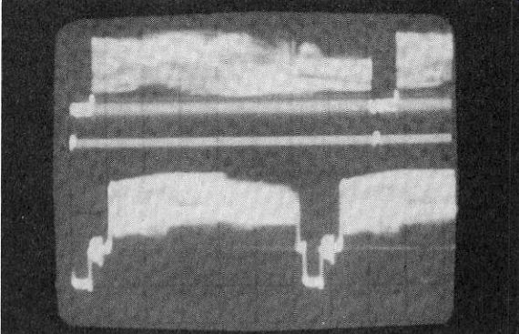
Fig. 1-7. Composite video signals at a 59.94-Hz field rate (top) and a 15,734-Hz
line rate (bottom). Due to the necessary double exposure (you can't look at
both simultaneously with a single time base scope) they are a little smeary.
---------
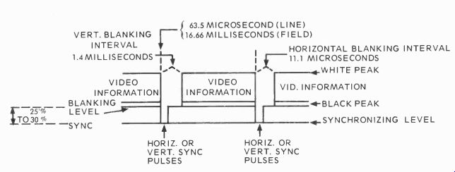
Fig. 1-8. A standard video waveform is very similar in appearance at both
line (horizontal) and field (vertical) scope sweep frequencies. The difference
is that at the line rate you're only viewing one or perhaps two lines of information,
while at the field rate you see the entire raster scanned once for a field
and twice (two complete cycles) for a frame (complete picture).
-----------------
Fig. 1-8 is almost self explanatory, except perhaps for times given for one full cycle at the horizontal rate and another full cycle at the vertical rate. The two blanking intervals are also given for the different waveforms, just as though the trace had a dual time base. Actually, the two traces appear very much the same, except that instead of looking at a single line of information at the horizontal rate, you're looking at a single field (one 60th sec) for each 16.6 millisecond interval, followed by the second 262.5 lines if you are showing a second vertical field after the 1.4 millisecond blanking interval. The same is true for the horizontal composite waveform; each full cycle is a new line, and you can have a number of lines in succession, depending on the setting of your oscilloscope's time base.
One additional feature well worth mentioning is the relative black-white-sync levels in the composite waveform.
Black is 75 percent of the waveform amplitude; white, 12.5 percent; sync and equalizing pulses range between 75 and 100 percent of the entire envelope amplitude. A knowledge of these proportions will be thoroughly worthwhile later when troubleshooting, modifying, or designing video, AGC, and sync stages of any television receiver.
Color Signal
Basically, we've been talking about monochrome vertical and horizontal sync rates-60 Hz ( or 16.6 msec) and 15,750 Hz (or 63.5 microseconds). In color transmission, these frequencies are slightly different-59.94 Hz for vertical and 15,734.264 Hz horizontal-but both are well within the design tolerance of monochrome receivers. The reason for this minute change is to make the color information fit the trans mitted waveform envelope and interleave color sidebands with luminance information in the Y channel.
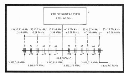
Fig. 1-9. Whole harmonics of the line scanning frequency lie between pods
of color information. Both are separated by successive multiples of 15,734-Hz
clusters on either side of the color subcarrier. The process is called interleaving,
and effectively separates chroma and luminance so both can modulate the same
video envelope without undue interference.
The luminance signal is transmitted as vestigial sideband information and it modulates the video carrier in both color and monochrome transmissions. The I and Q intelligence, however, separately amplitude modulate a pair of 90-degree out-of-phase 3.58-MHz carriers that are suppressed and, consequently, must then amplitude modulate the video carrier. Since the 3.58-MHz carrier is a modulation component of the same Y video carrier, the two color carriers are called subcarriers, and are so referenced throughout the remainder of the book. These subcarriers, of course, have identical 3,579,545-Hz frequencies and similarly position the color in formation on either side of the fundamentals as illustrated in Fig. 1-5.
To blend the color (chroma) information into the video envelope where monochrome signals don't exist, the altered horizontal frequency is now used directly. Again, in Fig. 1-9 we show the color subcarrier in the central position, as chroma is interleaved between the various harmonics of the monochrome single sideband clusters. Many books state that interleaving takes place at odd multiples of half the line scanning frequency and this is true, but it's a little hard to visualize. Let's just say that if you add and subtract 15.734, 264 kHz to and from the 3.579,545 MHz subcarrier, the chroma information will be effectively inserted at multiple points that will not interfere with the luminance (Y) information. This process is called interleaving. Also, on alternate scan lines, the burst information is transmitted 180 degrees out-of-phase and tends to null (cancel), leaving less interference in the picture.
What's actually happening is due to the fact that the broadcast signal contains many sine waves consisting of harmonics of the line and dual field frequencies with clusters of information gathered about each harmonic at whole--NOT half--multiples of the line and frame (two fields to a frame) frequencies. So if a new carrier with its chroma sidebands is set high in the AM luminance envelope between harmonics of the horizontal scan frequency, there will be little or no interference with brightness (Y) information and the color can be successfully inserted in this envelope at the sum and difference frequencies shown. In the diagram, the two double vertical lines marked M are the monochrome clusters, while each group of three lines with the letters C above are the color pods.
V. I, & Q SIGNALS
Basically, the luminance signal has a bandwidth of from 0 to 4.2 MHz. The color passbands, of course, are 1.5 MHz for I and 0.5 MHz for Q. Y is produced by the combined outputs of the three color camera tubes and is composed of the following red, blue, and green signal proportions (go two points right for decimal percentages): Y is 0.30 red + 0.59 green + 0.11 blue.
Here, the brightness of the entire picture should, at all times, be directly proportional to its color parts, something known as gamma-a correctable condition in the color processing cam era amplifier done with shading circuits at a solidly clamped black level. Gamma is defined as the ratio of light to signal and is the numerical exponent (such as Y equals X2) of any curve describing the light input in lumens to the camera tube output in volts. There is a gamma distortion circuit in the camera processor that actually distorts this relatively linear output signal so that the nonlinear cathode ray tube in any receiver can produce a corrected light-signal ratio of both luminance and chroma. Notice in Fig. 1-10 that the luminance signal is taken off the underside of the RGB matrix whether or not there is an incoming color signal.
The 0 to 1.5-MHz I information is made up of the following proportions of the RGB signal: I is 0.60 red-0.28 green-0.32 blue. The Q (0 to 0.5 MHz) intelligence is generated with still other sums and subtractions of the RGB signal in these proportions: Q is 0.21 red-0.52 green + 0.31 blue. Observe that in the RGB matrix we are combining red, blue and green signals and producing an output of I and Q signals that go to the balanced modulators. When this process is reversed in the receiver, the red, blue, and green outputs are in the following form if the primary colors were derived entirely from I, Q, and Y which, of course, they are NOT, but only because the I and Q information is shifted 33 degrees to R-Y, B-Y, G-Y and then recovered as RGB with the luminance Y signal added. An I-Q recovery receiver would be very expensive, and the RGB-(Y) system gives almost as good results.
The RGB signals are composed of the following proportions:
R is 0.941 + 0.62Q + Y, G is 0.271 + 0.65Q + Y, and B is 1.11I + 1.7Q + Y.
In monochrome pictures, a small difference in the luminance signal would not be especially noticed. But in color, even a very small error will result in considerable change that would be obvious to any viewer.
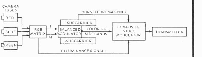
Fig. 1-10. Diagram illustrating how color signals are formed. I, Y and Q
signals are combined with 90-degree out-of-phase subcarriers that are suppressed
(cancelled) by balanced modulators. When there is no color, the two demodulators
go to zero and only luminance is transmitted.
After the matrix changes RGB to I and Q, the two signals are injected into a pair of balanced modulators with 3.58-MHz carriers that are 90 degrees out of phase with one another.
These balanced modulators then cancel (or suppress) the out-of-phase carriers and the two-variable I and Q amplitude modulated sidebands are put into the composite video envelope along with burst (for sync) and luminance information for black-and-white detail. The transmitter takes over and puts luminance, monochrome, and color sync signals on the air.
CAMERA TUBES
Cameras and camera tubes are increasing constantly in efficiency and image resolution as the electronic industry develops. The image Orthicon-the standard of color television for so many years-is beginning to be replaced, at least to some extent by the Visticon and the Plumbicon, made by RCA and North American Philips, respectively. The image orthicon has a target material of glass and lacks low light level sensitivity. As its globules lose efficiency, changes take place in the glass target and cause a "sticky" effect that can be seen as image retention when one scene is viewed following another. The new Visticons and Plumbicons have diodes that are considerably more sensitive, making the targets that respond to light focused by the camera lens an orderly sea of small, light-sensitive conductors with a highly uniform output.
It's interesting to realize that if one or more of these diodes shorts (and they sometimes do), you can see a pinpoint of light on the studio monitor that immediately identifies this condition. Sometimes the diodes "heal" themselves and resume their normal electronic conduction; but if they don't, then the tubes must be changed. Image orthicons have lasted as long as 40,000 hours, the Plumbicons and Visticons may or may not have as many hours of life; it's too early yet to tell. Visticons and Plumbicons are really lead-oxide vidicons with diode targets-another step along with electronics ladder toward better pictures for television.
THE COMPLETE TRANSMITTER
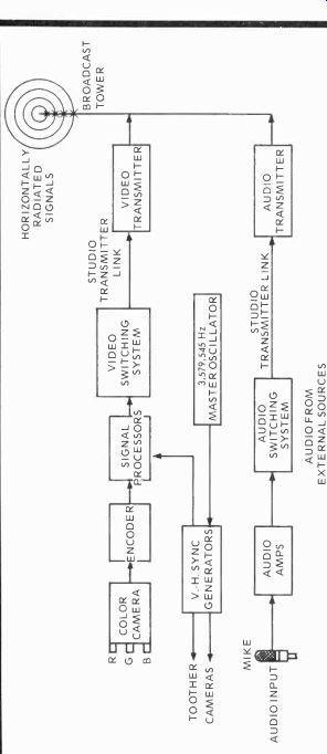
Fig. 1-11. Sync, blanking and audio are added to color (or monochrome) to
complete the TV signal. Especially notice that the master oscillator for the
entire system is the color subcarrier (Courtesy John Platt, NBC).
Fig. 1-10 is a diagram of the complete color part of a transmission system showing how chroma, color sync, and luminance signals are combined before delivery to the broadcast antennas. However, additional signals must be added to the composite chroma and luminance information to produce a stable and complete transmission, along with the necessary sound. Fig. 1-11 includes the remaining elements of the overall system so you will have a workable mental picture of the entire process. The additional necessities in either color or monochrome are the vertical and horizontal sync signals and sound.
Both camera (s) and the signal processing circuits must receive blanking vertical, and horizontal sync pulses for sweep-timing which controls camera operation. The same synchronizing pulses (Fig. 1-6) are transmitted over the air and used by any receiver for horizontal and vertical sync. In older sets, blanking pulses eliminated vertical retrace lines that would appear after each field, while horizontal blanking pulses blanked the CRT beam during horizontal retrace periods. Most color receivers now have multiple means of vertical and horizontal regenerated pulse blanking instead of the unsophisticated methods used especially in early monochrome TV. The sync pulses, of course, are of greater amplitude than the blanking pulses; they extend into the blacker than black region and so are easily separated by the receiver and diverted to the HV synchronizing circuits.
Transmitter sync and blanking pulses are precise, crystal controlled rectangular pulses that are binary counted down from a master oscillator to the exact microsecond duration and repetition rates required, and then combined as in Fig. 1-6 for broadcast.
The audio portion of the transmitted signal is produced by typical studio equipment (microphones, switching systems and amplifiers). Today, most such equipment is transistorized and the handling of this portion of each telecast is relatively simple except for the ever vigilant engineer "riding gain" on the sound mixers and amplitude controls. The output goes through the studio-transmitter link to the audio section of the transmitter where it is combined with that of the video transmitter. Both carriers are broadcast within the 6-MHz allowable bandwidth (Fig. 1-2). The sound is centered in the transmission envelope, at 5.75 MHz, 50 kHz wide, and exactly 4.5 MHz separated from the video carrier at 1.25 MHz. In any monochrome or color transmission, therefore, the sound is always 4.5 MHz above the video carrier and should so be displayed on any receiver tuner response curve over a relatively flat-top response. The 4.5 MHz "intercarrier" difference between the audio and video carriers is given greater attention when we discuss receiver sound in Section 6.
The transmitting antenna is usually placed on top of tall city buildings or equally high towers so that it may radiate a horizontally polarized signal that is basically circular, although the broadcast pattern may be shaped. Both video and audio are radiated from the same structure through a bridge arrangement called a diplexer that permits the two transmitters to use the same antenna without disruptive interaction. When the bridge is balanced, there is no harmful feedback from one to the other and each transmitter may deliver full power to the single radiating antenna. The antenna and transmission lines must match closely, or delayed images can be reflected from the antenna back to the transmitter, reflected a second time, then radiated with a time delay that is twice the electrical length of the initial transmission line.
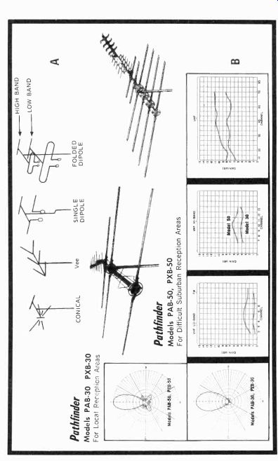
Fig. 1-12. Older types of VHF (A). New Jerrold log periodic local or suburban
antennas with separately directed front arrays (B).
RECEIVING ANTENNAS
Because of earth-parallel polarization, receiving antennas must also accept electromagnetic television signals in the horizontal plane and be tuned to pick up either the VHF, UHF, or VHF-UHF combined transmissions. Naturally, there has to be a transmission line. And this line, like that of the transmitter's, has to be matched to the antenna and receiver to avoid what are known as standing waves (commonly referred to as the standing wave ratio or SWR), which induce ghosts and result in a loss of antenna gain, thus limiting the signal input at the RF terminals of the receiver.
With more than 20 years behind us in television trans mission and reception, manufacturers have come a long way from the conical, vee, single folded dipole narrow hand antennas (Fig. 1-12A) to very complex arrays that are multi tuned, computer designed, often UHF-VHF combinations, and some, like the new Jerrold Pathfinder log periodic local and suburban antennas in Fig. 1-12B, have directional arrays for separate UHF station selection. Of course, both antennas receive full VHF-UHF transmissions. It's interesting to note the difference in gains as receiving elements are increased in number for suburban reception.
With a UHF station at, say Channel 45, we come down a 300-ohm oval shielded or non-shielded line (depending on reflections or noise) at 11 db of gain into the RF terminals of the receiver. Or, should the antenna be a 75-ohm variety (as this one can be also) a matching coaxial cable (single conductor) lead-in could be used that would connect directly into the tuner of the better new receivers. With the 300-ohm cable, the signals pass through a balanced-to-unbalanced trans former-like termination (balun) to match the 300-ohm line impedance to the 72-ohm receiver.
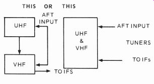
Fig. 1-13. Separate or combined UHF-VHF tuners are found in the newest television
receivers. Most have AFT oscillator control from the third video IF.
TUNERS
Modern VHF tuners are usually either switch or turret types, while UHF tuners are virtually all the rotary capacitor variety-at least for the time being (Fig. 1-13). Varactor controlled tuners, however, are rapidly coming more into use, although there are a few small problems with the control diodes yet to be solved, and the DC energizing voltages usually have to be well regulated. Some receivers also offer push button controlled UHF selectors, and others have 13 or more detented channels so that the rotors switch into place. In any event, contemporary UHF tuners usually have a simple oscillator and mixing diode, without an RF amplifier, although there may be UHF RFs very shortly. The VHF counterparts all have at least one RF amplifier, a mixer, and a local oscillator, called by many in the past, the first detector.
Individual 6-MHz bandpass RF signals from the 12 VHF channels and 70 UHF stations may then be selected by the receiver's tuners, amplified, and converted to an intermediate IF frequency of 44.25 MHz. The UHF tuner, normally having no RF amplifier, picks up additional gain from the VHF tuner with added amplification by the VHF RF amplifier and mixer.
The VHF oscillator is inoperative (usually no B+) while ultra high frequencies are being received. VHF-UHF channels and the corresponding frequencies are listed in Table 1-1.
IF & AFT AMPLIFIERS
In some receivers, coupling, certain bandpass shaping, impedance matching, and selectivity is insured by a tuned circuit between the tuners and video IF amplifiers. While in others, nothing more than a coaxial cable links the RF section with the IFs. In all instances where there are links, they have to be sweep aligned to match the tuner with the IF, if either radio frequency or intermediate frequency circuits are replaced or modified. Where repairs simply mean physically replacing a same-value resistor or capacitor, alignment is usually not necessary unless, of course, the component was defective when the initial alignment was executed.
IFs are the basic band-shaping medium-to-high gain amplifiers that are normally stagger tuned so the overall-not individual circuit-response determines the bandwidth of the circuit. The first video IF is almost always controlled by a varying DC voltage derived after the video detector, called automatic gain control (AGC). The second stage is often regulated by the same voltage too, so that the IF amplifiers will not overload and cause sync problems, usually vertical.
Traps to remove unwanted carriers, such as audio, are also included, as are various tuning (coupling) schemes to get signals from one stage to the next with maximum linearity, least loss, and best gain. Signals coming into an IF strip are at best in the millivolt range, and must be amplified to 4 or 5 volts, with load, before being detected and passed on to the video amplifiers. The critical stage in any IF amplifier is usually the third IF, since it passes the most current for the greatest voltage swing and IF amplification.
As you observe in Fig. 1-14, tube-type video IFs usually have at least two stages (sometimes three) but three or four transistors are always used in this same circuit because of the smaller voltage swing with the 22 to 35-volt DC supplies.
Vacuum tube IFs often have 180-volt static sources, and "stacked," can function at between 200 to 300 WVDC.
However, the IF vacuum tube stage doesn't have the small signal transistor's bandpass, longevity, easy DC operation, lack of harmonics, and little or no case dissipation. A tube always runs hot and, in many instances, has forever been a demon to tube sockets and printed circuit boards.
The AFT automatic fine tuning system is best described as a frequency discriminator to DC converter that should linearly feed back a proportional DC correction voltage for a deviation on either side of the 45.75-MHz video IF carrier. Such action controls the local oscillator in the tuner and puts the tuner back on the selected channel frequency. Almost universally, AFT correction voltages are taken off the collector of the third IF, similar to the method used to pick off audio signal.
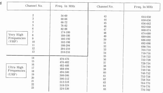
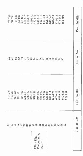
Table 1-1. VHF and UHF channel designations.
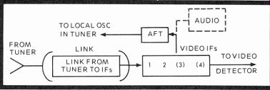
Fig. 1-14. Block diagram of the tuner and video IF link connector on many
older sets, using 2, 3 or 4 stages of video IF. Automatic fine tuning (AFT)
keeps the local oscillator in the receiver from drifting off proper tuning.
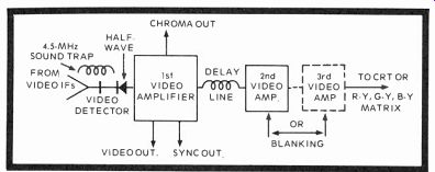
Fig. 1-15. Block diagram of a diode half-wave video detector followed by
two or more video amplifiers with an 0.8-microsecond delay line in between.
VIDEO DETECTOR & AMPLIFIERS
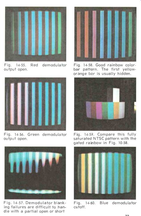
Fig. 14-55. Red demodulator output open.
Fig. 14-56. Green demodulator output open.
Fig. 14-57. Demodulator blanking failures are difficult to handle with a partial open or short
Fig. 14-58. Good rainbow color-bar pattern. The first yellow-orange bar is usually hidden.
Fig. 14-59. Compare this fully saturated NTSC pattern with the gated rainbow in Fig. 10-58.
Fig. 14-60. Blue demodulator cutoff.
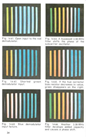
Fig. 14-61. Open input to the red demodulator.
Fig. 14-64. A bypassed 3.58-MHz filter shifts the phase of the subcarrier oscillator.
Fig. 14-62. Shorted green demodulator input.
Fig. 14-63. Blue demodulator input failure.
Fig. 14-65. If the hue corrector bias resistor decreases in value, green disappears on the right.
Fig. 14-66. Another 3.58-MHz filter develops added capacity and causes a phase shift.
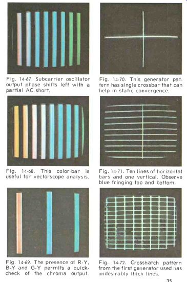
Fig. 14-67. Subcarrier oscillator output phase shifts left with a partial AC short.
Fig. 14-68. This color-bar is useful for vectorscope analysis.
Fig. 14-69. The presence 01 R-Y, B-Y and G-Y permits a quick-check of the chroma output.
Fig. 14-70. This generator pattern has single crossbar that can help in static convergence.
Fig. 14-71. Ten lines of horizontal bars and one vertical. Observe blue fringing top and bottom.
Fig. 14-72. Crosshatch pattern from the first generator used has undesirably thick lines.
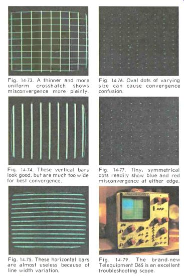
Fig. 14-73. A thinner and more uniform crosshatch shows misconvergence more plainly.
Fig. 14-74. These vertical bars look good, but are much too wide for best convergence.
Fig. 14-75. These horizontal bars are almost useless because of line width variation.
Fig. 14-76. Oval dots of varying size can cause convergence confusion.
Fig. 14-77. Tiny, symmetrical dots readily show blue and red misconvergence at either edge.
Fig. 14-79. The brand-new Telequipment D65 is an excellent troubleshooting scope.
The video detector (sometimes called the second detector) is usually a half-wave rectifier diode (Fig. 1-15), although there are probably full-wave IC rectifiers on the way. Normally, it receives the IF signals on the cathode, blocking the positive portions of diode conduction but passing negative composite video so that sync pulses and noise will be pointed toward blacker than black and, therefore, not appear in the picture. Usually, in color anyway, a video detector has a 4.5 MHz intercarrier sound trap before it as a last resort to block sound frequencies before they enter the amplified video chain and become interference in the picture. Around the video detector there are also peaking coils to increase high-frequency response.
The first video stage is the initial amplifier of demodulated composite video containing all sync, monochrome, and chroma information to be used by the remainder of the receiver's circuits. The capacitance, inductance, and passband characteristics of the video detector and video IFs often cause a video "tilt" that usually requires compensation in the chroma IFs. Also, because of the additional signal processing in the chroma circuits, there has to be an 0.8-microsecond delay in the luminance channel so that chroma and luminance information can drive the final picture tube amplifiers or CRT grids at the same instant in time. The first video amplifier, therefore, supplies some of the usual video, and certainly chroma and sync information, to the various other processing circuits in the receiver.
After the delay line, the luminance (video) signals are sent to one or more additional amplifiers, depending on the requirements of the cathode ray tube and the manufacturer's design team. These add further gain to the luminance monochrome signal which is usually no more than 3.6 MHz on good color receivers, equal to or less than 2.8 MHz on poor ones, and somewhere in between when processed by monochrome receivers, depending more or less on price. If the bandwidth on a color receiver is too wide, there will be a collision between luminance and chroma, and this will show as fine-line (or herringbone) interference all over the screen.
We'll look at receiver frequency response later with the vertical interval test signals (VIT) that are dependable evaluators of color receivers, with but few predictable reservations.
AGC, SYNC & NOISE CIRCUITS
AGC and noise circuits vary from receiver to receiver, but sync separators and amplifiers are relatively standard. The ideal circuit would be something like the diagram in Fig. 1-16, where the noise gate would act on both the AGC amplifier and sync separator alike when noise pulses arrive. If it did, here's what would happen: Incoming negative video would supply both the AGC amplifier and sync separator with picture and sync information that each could use for its respective operations. The automatic gain control amplifier is AC operated from flyback pulses obtained through a winding on the horizontal output transformer. The sync separator must
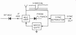
Fig. 1-16. Block diagram of the AGC, sync separator and noise gate combination
found in some receivers.
strip all video from the composite video-sync signal and present only horizontal and vertical sync information to the receiver's sync circuits. As more video signal is received, the AGC amplifier conducts harder and supplies more forward bias AGC to the (semiconductor) video IF amplifiers which begin to shut off conduction current when forward DC becomes abnormal. On very strong signals the RF AGC delay begins operating when the IF AGC forward voltage has risen more than 0.7 volt (the forward diode drop) and the RF amplifier in the tuner amplifies less. Now, the IF transistors and the RF transistor or FET all conduct less, resulting in greatly reduced overall gain. In vacuum tube receivers, the bias would be negative so that tube grids would be driven less positive, thereby reducing conduction by cutting down the flow of electrons through the tube.
As you must already know, when there are no sync pulses, the horizontal and vertical multivibrators operate all by themselves at set time constants and DC levels and, therefore, produce a steady raster. With a signal input, however, the sweep circuits must be timed so they are in step with the transmitted signal in all respects. The incoming video signal at the sync amplifier input is in negative polarity. So if a large spike of transient voltage (any unusual inside or outside interference-usually outside) spears the composite video, the noise gate can be designed so that it shunts this transient to ground, and at the same time biases the AGC. Then, both the sync and video signals are blanked, the spike of errant voltage (only a few microseconds or so in duration) is shunted aside, and an observer never knows the difference. As you can see, noise circuits, designed properly, are thoroughly useful in any set, especially the better color receivers.
With respect to video transmission, negative video modulation is used in this country for better automatic gain control, since sync tips are held constant. Also, the peak transmitter power output is 30 percent greater with negative modulation than with positive modulation. With negative modulation, noise also appears as black interference instead of white, a condition that is certainly less noticeable to the eye.
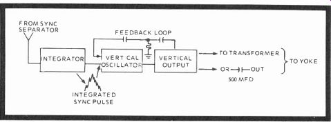
Fig. 1-17. Block diagram of a typical vertical oscillator and output sweep
system. It is driven by an integrator drive pulse and coupled by transformer
or capacitor to the vertical deflection yoke, with further coupling to convergence
and pincushion subsystems.
VERTICAL OSCILLATOR & OUTPUT
These circuits are mostly the feedback type, with an extra driver included in the transistorized versions (Fig. 1-17).
Really, all they amount to is a pair or tubes (probably in the same envelope) three or more transistors or, in one instance, a single integrated circuit mounted on a heat sink. In all cases, however, feedback signals from the output tube, or driver transistor, go to the oscillator to sustain "flywheel" oscillations during times of no incoming sync signals. There are linearity controls to correct conduction curves and height controls to stretch the picture to cover the face of the cathode ray tube. Sync pulses at a 59.94-Hz (16.66 msec) rate are differentiated and used to sync the vertical oscillator which must have an accuracy of 3 microseconds, or one part in 5,000-a tolerance that is 8 times more critical than the horizontal scan time. Therefore, sync troubles will usually affect the vertical oscillator first, if sync jitter or other instability is the problem.
There's nothing especially new in vertical oscillators, but the output sections of some transistorized modular receivers have changed drastically, and in several of these, there is no longer any vertical output transformer as we've known it since the advent of television-only a complementary push pull arrangement of two stacked transistors with a 500-mfd coupling capacitor feeding to the deflection yoke. This circuit is a logical development from a similar audio speaker-driver circuit first introduced, we believe, by Motorola in 1969 or 1970, depending on what is considered the model year.
The total vertical trace time is 16,662 microseconds (16.662 milliseconds), a blanking period of about 1.4 millisecond for each field. Two fields constitute a frame, and 30 frames per second is just above the 24-frame flicker rate our eyes recognize. The input circuit to all vertical oscillators is an integrator that is actually a low-pass filter designed to screen out the faster horizontal pulses and deliver only slowly integrated vertical pulses that either cut off or drive on the vertical oscillator, depending on the particular sync system.
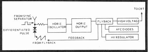
Fig. 1-18. Horizontal sweep system block diagram including oscillator, output,
high-voltage, regulation and feedback.
HORIZONTAL OSCILLATOR & OUTPUT
The horizontal oscillator, like the vertical oscillator, has sync and feedback circuits, too, but they are somewhat different (Fig. 1-18). The differentiated horizontal sync pulses are the timing chain for this circuit when the set is tuned to a signal. Its input is, of course, an RC differentiator, with the network resistor connected to ground. The resistor and its associated capacitor form a time constant that will both block the vertical sync frequencies and allow a reasonable rise and fall time for timing the horizontal oscillator. There are, however, automatic frequency control diodes (AFC) that take the output transformer's feedback pulse, compare it with the incoming sync signal, and then put out a DC correction voltage for oscillator lock. If the oscillator free runs correctly with no incoming signal, then stays locked in sync with incoming signal, you know that both sync and oscillator circuits are operating as they were designed. An out-of-sync condition with no incoming signal denotes oscillator problems, while a sync clip with incoming signal tells you there is probably sync compression somewhere or other faults in, or ahead of, the sync separator.
A semi-trapezoidal or rectangular-shaped pulse signal is produced by tube or semiconductor oscillators and is used to drive the horizontal output stage. The output stage supplies a horizontal output transformer, horizontal deflection yoke, pincushion transformer (on most sets), and the dynamic convergence coils. This takes a sizable power tube or one or two heavily rated transistors or silicon controlled rectifiers to drive such circuitry. In combination, the oscillator and horizontal output are among the most critical parts of a color television receiver. For, in addition to exciting the various inductors that deflect and converge the three CRT beams, the collapsing magnetic field of the horizontal output trans former must form a high-voltage spike that can be converted into focus voltage, B-boost voltage, other pulse drive sources, and 25 to 30 kilovolts to light the picture tube. Also, all this has to have regulation so that the CRT intensity will remain relatively constant and the picture tube will not draw too much beam current during maximum picture brightness. This is why the high voltage is always adjusted with the brightness control turned to minimum, since you don't have to depend on the regulators which are not fully operating at this point.
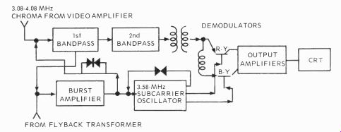
Fig. 1-19. Chroma amplifiers, bandpass amplifier, demodulators, output amplifiers,
and the cathode ray tube comprise the chroma circuits. G-Y, as such, is not
transmitted.
TILE CHROMA CIRCUITS
The last of the video receiving blocks in this initial description are the chroma circuits (Fig. 1-19). If you will simply consider these color processors as just another sub system among the previous groupings and remember each of the basic subsections, you should have little difficulty.
Initially, you recall that the chroma information out of the transmitter contains double and single sideband modulation on either side of the 3.58-MHz suppressed carrier. The chroma signals are interleaved among the monochrome modulation at sum and difference multiples of the horizontal scanning frequency. The receiver actually accepts I and Q signals as transmitted, but the set is both a little less broad-banded and also shifts the phase of the incoming chroma 33 degrees right (clockwise) so that R-Y and B-Y information is processed instead. And since the eye can't tell without immediate reference that I information above 0.5 MHz is not included, the receiver also attenuates the 0.6 to 1.5 MHz color information, permitting just the double 0 to 0.5 MHz I and Q sidebands in the form of R-Y and B-Y to pass to the color amplifiers.
The color amplifiers are called bandpass amplifiers because their function is to conduct and amplify only the 3 to 4 MHz information 0.5 MHz on either side of the 3.58-MHz subcarrier. Other chroma circuit terminology includes the chroma IFs and sometimes, in integrated circuits, gain-controlled amplifiers. But they will still do the same thing: permit passage of only color frequencies between 3.08 and 4.08 MHz for eventual processing by the color demodulators. Of course, there are DC correction and control circuits along the way, such as automatic chroma control and, in one receiver, an additional DC automatic control of the second chroma amplifier.
Also recall the 8-11 cycles of burst on the back porch of the horizontal sync pedestal. This is the color sync signal which is applied to a burst amplifier that is gated into conduction by a winding on the flyback transformer every 63.5 microseconds, or at the end of each horizontal scan line. Color sync rings a crystal or is compared with feedback from the 3.579,545-MHz receiver-generated subcarrier oscillator. If the oscillator frequency differs, a DC correction voltage is produced that syncs the local oscillator with that of the suppressed carriers at the transmitter. The amplitude of the incoming burst is somewhat proportional to the received chroma, and another DC voltage is generated to control conduction of the first chroma (bandpass) amplifier within relatively small excursions.
The regenerated chroma subcarrier now supplies one or more signals to a pair of diodes, a pair of transistors, three transistors, or an integrated circuit known as the chroma demodulator. The conducting demodulators pass the chroma signals to either an output matrix comprised of additional transistors, or matrix the chroma internally, or supply R-Y, B-Y, G-Y information to the grids of the cathode ray tube where the chroma and luminance signals are matrixed. This latter method, of course, is the older system and less and less manufacturers are using it since there are many advantages to passing red, blue, and green information directly to the cathodes of the picture tube already mixed with brightness intelligence. You'll see why when we analyze the several types of demodulators.
SOUND SECTION
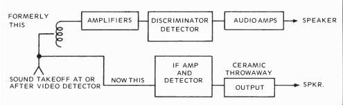
Fig. 1-20. The sound subsystem uses either tubes, discrete semiconductors,
or all integrated circuits.
The sound section (Fig. 1-20) completes this preliminary discussion of the receiver. The difference signal between the 45.75-MHz video carrier and the 41.25-MHz sound carrier creates a new frequency modulation carrier at 4.5 MHz. The original sound carrier is trapped out. The difference signal must pass through a frequency discrimination circuit, be amplified, and then detected by various means that have included several types of discriminators, ratio detectors, quadrature locked oscillators, gated beam detectors, etc. The latest systems use integrated circuits, with various internal amplifiers, peak detectors, and output amplifiers all rolled into one. The newest audio output circuits have complementary transistors like the vertical circuit previously described and an AC coupling capacitor instead of a DC operated transformer. Also, some audio circuits, and some video and sync circuits too, are being made of thick film and transistor chips on ceramic substrates. All will be what the industry calls "throwaways"; in other words, non-repairable.
FM detection converts carrier frequency deviations to a current response, where the current generates a ratio-like voltage that is proportional in duration and amplitude to any and all carrier variations.
SOLID-STATE RECEIVER
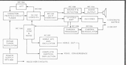
Fig. 1-21. A Motorola ( Phoenix) version of a virtually all-integrated circuit
receiver (Courtesy Ben Scott and Motorola, Phoenix, Ariz.)
To conclude this first section, it seems the discussion is completely up to date with the block diagram of a virtually all-integrated circuit color television receiver (Fig. 1-20) developed by Motorola, Phoenix, Ariz., a product of Motorola Semiconductor Consumer products, and Benton B. Scott, Manager, TV-Tuner Section Applications Engineering.
The tuner can be a printed circuit, varactor-operated type; the IFs, AFT and video detector, a trio of ICs; the AGC, noise and sync are in an MC1345 IC, the horizontal AFC and oscillator, an experimental XC1391; tuner regulator, an MVS460; the power supply, an MFC4060; sound IF and audio outputs, another pair of ICs; the chroma demodulator, an MC1326; chroma processor, an MC1393; and the vertical deflection, a second experimental XC1390-a circuit that won the Broadcast and TV Receiver IEEE Group's 1971 award.
The day of an all IC receiver may not be long in coming.
QUESTIONS
1. What other energy travels at the same speed as light?
2. Light and what travel at the rate of 3 x 10^8 meters per second?
3. Radio waves consist of what kind of fields?
4. Modulated transmitted waves must undergo what two variations?
5. Define amplitude (AM) and frequency (FM) modulation?
6. What sidebands are especially important in the study of color television?
7. Name two sidebands on either side of the color sub-carrier.
8. How many TV channels are there presently allocated and what is the individual bandwidth?
9. What is the VHF-FM bandspread? UHF bandspread?
10. How do I and Q sidebands relate to burst?
11. What are the differences in degrees between I, Q, and burst?
12. What are the time intervals for vertical and horizontal blanking?
13. Define the horizontal and vertical blanking intervals in terms of time.
14. Sync information is broadcast only during.
15. Black is what percentage of the composite waveform's amplitude? White? Sync Peaks?
16. What are the vertical and horizontal repetition rates for color TV transmissions? Chroma subcarriers?
17. Chroma is inserted at what basic frequency on either side of the subcarrier?
18. What colors comprise the luminance signal and what are their proportions?
19. Draw a diagram of the transmitted I, Y, and Q signals from camera to transmitter.
20. In transmission, is audio above or below the video carrier, and by how much?
21. Why must antenna and transmission lines at the transmitter and receiver be matched?
22. What is the sync reference for the entire color TV transmitter?
23. What happens when receiver video IF amplifiers are allowed to overload? Will audio sometimes buzz?
24. Describe an automatic fine tuning circuit.
25. Do we have positive or negative video modulation in the U.S., and why?
Next: Colorimetry & Picture Tubes
Also see:
TV Antennas and Transmission lines
Air Time--An Intro to Television Broadcasting
TV and Radio Tube Troubles (1958)