With cable television serving 5.5 million homes already in this country through 2700 systems and, by 1975, 1.7 million more are expected, this industry's size and potential is already formidable. In the not too distant future, two-way communications to and from many CATV subscribers' homes may well be in operation, offering shopping services, computer links, banking, schooling, trend polling, and even employment to those who wish such services.
For a good look at CATV and what engineers and technicians are going to contend with, we went to Philadelphia, Pa., and talked with Jerrold Director of Technical Operations, Mr. Caywood C. Cooley, Jr. First we asked, "How do you go about setting up a CATV facility?" And this, generally, was his reply (Figs. 15-1 through 15-4).
SEE FIGURE 15.3
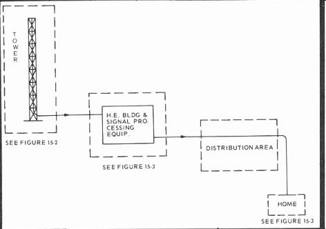
Fig. 15-1. "Standardized" type CATV system showing major blocks
with details spelled out in Figs. 15-2, 15-3 and 15-4.
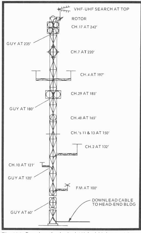
Fig. 15-2. Drawing of a typical 250-foot high guyed tower designed to support
receiving antennas for various channels.
-------------------
HEAD-END EQUIPMENT LEGEND
1. ANTENNA
2. DOWNLEAD CABLE
3. SPLITTER-COMBINER
4. PASSBAND FILTER (UHF)
5. PREAMP (VHF OR UHF)
6. CONVERTER (UHF TO VHF)
7. POWER SUPPLY
8. SPLITTER (2 WAY)
9. DIRECTIONAL COUPLER
10. TERMINATOR
11. PASSBAND FILTER (INPUT)
12. COMMANDER
13. PASSBAND FILTER (OUTPUT)
17. SPLITTER-MIXER (HI-LO)
14. ROTOR
18. CARRIER GENERATOR
15. ROTOR CABLE
19. PROBE (TEST POINT)
16. SPLITTER-MIXER (VHF-UHF)
20. TEST POINT
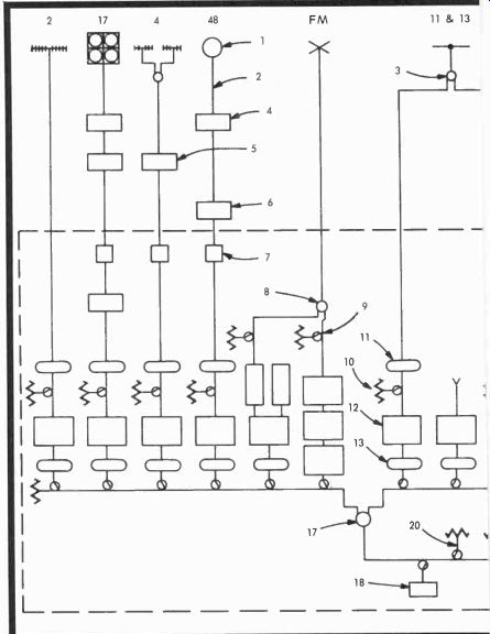
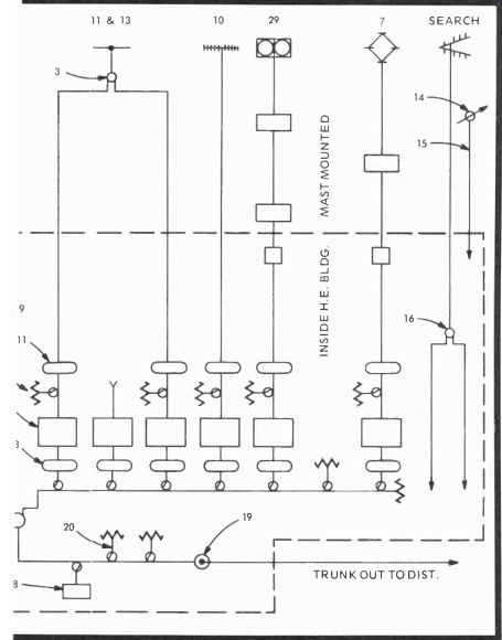
Fig. 15-3. Block diagram of the signal processing equipment in the head end.
-------------------
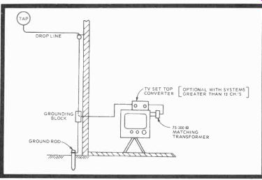

Fig. 15-4. Drop line from the cable tap feeds the home CATV installation.
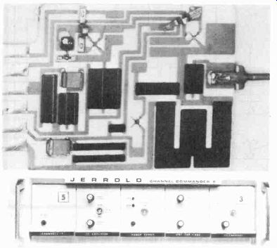
Fig. 15-5. Jerrold Channel Commander 11 signal processor. This one translates
Channel 5 to Channel 3.
First you select an antenna site, called a head end, make all sorts of signal measurements from ground level or from over-flights in light aircraft or helicopters, then negotiate for real estate. Meanwhile, avoid a site overlooking a city because of neon signs, etc.; pick a spot free from ghosting and differentials between video and sound caused by local propagation conditions.
When these conditions have been satisfied, the receiving antennas are selected. Log periodics are preferred, and are a must on the low-band channels. But on the high band, horizontally stacked yagis can be used to advantage to change pattern lobes, directional pickup, and the like. Next come the preamplifiers, then UHF to VHF converters, with UHF preamps fastened directly to the tower. Downleads are all through wideband static couplers, with cable in aluminum sheathing and either a polystyrene or polyfoam dielectric.
In the antenna shack, the received signals are fed into heterodyne signal processors such as that shown in Fig. 15-5. Video and sound are converted to two intermediate frequencies (IFs), then both are AGC controlled to establish a level and maintain a constant ratio between sound and picture carriers. In a normal broadcast transmission, the sound carrier is about 6 db below video, but in CATV, Mr. Cooley channel rejection in all but the very poorest receivers.
From the IF frequencies, the signal is beat back up (heterodyned) to the channel desired on the cable. Some systems use a single-channel, others a 26-channel tuner, which separates the various modulations on the carrier and puts a number of channels into a single channel through the tuner of a television receiver. If receiver top converters are used, amplifiers must suppress any second-order harmonics by output cancellation to avoid, say, a Channel 2 and a Channel 6 beat, that will fall at 140 MHz and give you problems if you're using that particular frequency. There's also cross modulation (one channel modulating another) which causes what is commonly known as a windshield wiper effect on the desired channel. It is caused by the horizontal blanking bar of the interfering channel when an amplifier is delivering more output than it should.
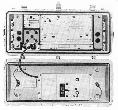
Fig. 15-6. A Jerrold Starline Twenty push-pull fully-loaded repeater amplifier
station SP-1.
CATV signals are then transmitted down main trunklines (Fig. 15-6) through feeders, splitters, and finally into line drops and subscriber homes. There are mainline repeater amplifiers positioned every 20 db down from the original signal level, usually about 2,000 feet apart. Repeater amplifier spacing is normally a function of the cable, the splitters, and directional couplers, and the various taps. There are also line bridging amplifiers which supply feeder lines and extenders (Fig. 15-7), couplers, line taps (splitters, Fig. 15-8), and finally the separate house drops.
Do you often find illegal taps, we asked? Sure, replied Mr. Cooley. But on holidays and during summer vacations, schoolboys and girls are sent out to count the number of taps in specific neighborhoods. "Illegal’s" are than confronted with the evidence and almost all of them take the service thereafter--or are hauled into court.
Are there problems? Obviously. About half the CATV service calls are traceable to the subscriber's receiver. The CATV technician carries a black-and-white receiver along with him and makes separate signal checks besides. He monitors the field strength of channels 2, 6, 7, and 13 at the tap.
If there is a complaint, these checks should certainly uncover the problem if it's a simple one. More complex difficulties usually require supervisory personnel with more elaborate equipment. For instance, main trunk measurements, made at the end of the CATV transmission line, include:
1. Signal-to-noise ratios
2. AGC pilot carrier modulation
3. All signal levels, including a look at the pictures
4. Hum modulation
5. Possibly a sweep response of the entire system periodically every two scanning lines, and in cases of bad problems, a system equalization every 30 seconds. Here, some oversensitive receivers may develop vertical roll during the sweeping period.
Of course, there is also head end maintenance, including tower inspections, cables, amplifier measurements, and possibly, spectrum analysis. With a solid-state system, only one man is needed for each hundred miles of line, whereas with tube equipment a man has to be assigned to each 40 miles of cable.
The outside television serviceman can look for the following problems:
1. Second- and third-order distortion, usually fine diagonal lines in the background that are sum and difference beats. If you want to know the fundamental interfering frequency, loosely couple a signal generator to the receiver's antenna terminals and match the interfering beat.
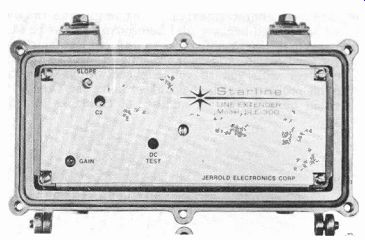
Fig. 15-7. Jerrold line extender, Model SLE-300.
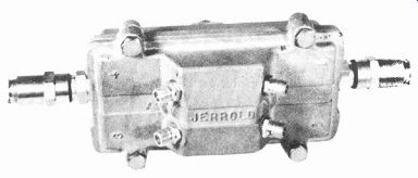
Fig. 15-8. A line tap that will serve four separate sub scribers.
2. Modulation envelope delay distortion usually occurs in the head and may appear as leading or trailing ghosts in B&W or color pictures. It may also show as a lack of crispness in the picture. The trouble can be verified by using a good off-the-air signal or, perhaps, a good color-bar generator. If the picture is clean by these methods, the cable is bad.
3. Where there are microwaves around, whites in the picture can be clipped, causing noisy sound, plus sync clipping that results in vertical rolling.
4. The color burst signal or color amplitude may be enlarged or reduced because of a heterodyne processor fault or problems in the CATV antennas. Again, use an outside color signal for verification. And, may we suggest, carry a reliable color receiver with you so you can show any subscriber whether his problems are in the cable or in his set. Otherwise, there could be a surprising number of callbacks as your "reward."
Next: Link | --Foreign TV Systems
Also see:
TV Antennas and Transmission lines
Air Time--An Intro to Television Broadcasting
TV and Radio Tube Troubles (1958)