The three guns in any color tube of the usual shadow mask variety are set 120 degrees apart from one another. Since they emits separate beams, each must initially be converged at the center of the CRT to form a single, uniform pattern. And if the right percentage of red, green, and blue beams are made to land the three RGB spots over the entire screen, the pure output with no incoming signal should be a clean, grayish white raster without contamination or shadows. Should one of the beams be tilted away from the other two, distinct fringes of the color produced by the displaced gun will outline larger objects or persons in the picture. Quite simply, this is called color fringing, and is objectionable on both black-and-white and color telecasts because it is distracting to any viewer.
COLOR PURITY
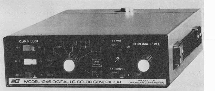
Fig. 4-1. B & K Model 1246 digital count-down IC color-bar generator.
---------
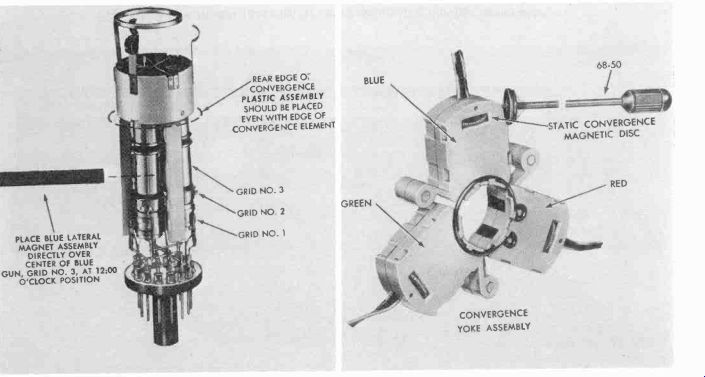
Fig. 4-2. Zenith CRT gun and stat yoke assembly for both hybrid and solid-state
receivers.
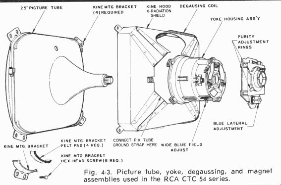
Fig. 4-3. Picture tube, yoke, degaussing, and magnet assemblies used in the
RCA CTC 54 series.
There is also the problem of color purity. If, after a receiver has been either manually and-or automatically degaussed, there is a medium-to-large splotch of undesirable color on the screen, this is an indication that the beams are striking other than their normally assigned phosphor dots, thus creating some undesirable primary hue that is called an impurity. Any adjustment to correct the condition is made only after connecting an RF dot-crosshatch generator (Fig. 4-1) to the RF antenna terminals. Then, the red, blue, and green static magnets (Fig. 4-2) and the blue lateral magnet are positioned for best center convergence as demonstrated by a series of vertical white dots or a bar in the middle of the raster. Then, the signal generator gun killer switches or screen controls are positioned so that two of the three CRT guns are cut off, usually leaving red (the previously least efficient phosphor, before 1969-1970) as the overall color for final adjustment. When this is done, locking hardware for the deflection yoke is loosened (Figs. 4-2 and 4-3) and the yoke is slid back toward the convergence assembly without either disturbing the convergence magnet assembly or tilting the deflection yoke. Tabs on the purity ring are then adjusted so that the purity magnet field cuts through the electron beams passing through the neck of the cathode ray tube, moving them at right angles to the field. When the tabs are spread (Fig. 4-4), the magnetic field strength increases and so does the amount of deflection; rotating the entire magnet moves the beams in a circular path. As the tabs are adjusted, a red ball (Fig. 4-5) appears on the center of the receiver.
Thereafter, the deflection yoke is slid forward until a uniform red field covers the entire face of the cathode ray tube. This is an actual adjustment of the deflection center near the bell of the tube. By alternately turning on and off the red, blue and green beams, the other two pure fields may be verified also.
Observe that the position of the yoke does not affect the electron beams that pass through its center and are not deflected, but only those spreading from the larger middle area to the edges of the rectangular CRT.
Should contamination still appear on certain portions of the screen, a manual degaussing should be undertaken to demagnetize the shadow mask and other metal objects in the screen area. If irregularities still persist, then either the purity magnet is defective, the degaussing coil is not doing its job (you might try it on another receiver), or the CRT shadow mask itself and-or phosphors are permanently affected. Occasionally, you may find a color receiver that has been placed close to a large current-consuming appliance such as an electric cook stove, oven, etc. Such appliances will radiate enough AC to magnetize shadow mask and other metal in the screen area. The only solution is a thorough manual degaussing. In the newer receivers, however, automatic degaussing, which occurs when the receiver is turned on should nullify any such occasional problem.
GRAY SCALE
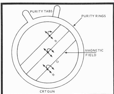
Fig. 4-4. Moving the purity ring tags together or apart decreases or increases
the field strength, respectively, while rotating the purity ring moves the
electron beams in a circle. Center dots are the beam starting points before
adjustment.
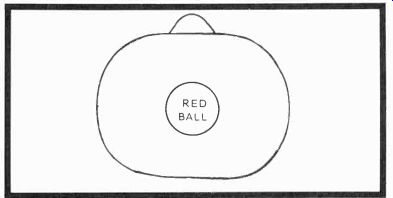
Fig. 4-5. A red ball appears as the tabs are adjusted for center purity,
then the yoke is moved forward for a uniform red (or blue, green) field over
the entire face of the CRT.
While many prefer to converge a receiver first, then proceed to gray-scale tracking, we think it's sometimes better to adjust the CRT biases immediately after purity checks, since you should have already done a static convergence during purity adjustments, leaving only a dynamic touchup as the final setup step. In this case, it's a matter of simple preference, and the order really makes little difference unless the receiver is so far out of convergence-a real rarity-that overlapping colors will give you problems in obtaining a gray-white screen. Should such a condition arise, there would be no alternative but to undertake convergence first.
Gray-scale adjustments vary somewhat from receiver to receiver (Fig. 4-6), and the only way to be certain of an absolutely correct procedure is to consult one of the TAB color manuals or the actual manufacturer's literature. What you're trying to do in gray-scale tracking is to set and maintain the three CRT gun beam currents at the same ratios throughout both the range of the brightness control and any and all in coming luminance signals. Beam currents are to be fixed at certain relative values after the cut-off (extinguish) point for each beam is determined. The actual CRT screen temperature sought is about 9300 degrees Kelvin, where K equals degrees Celsius + 273, and degrees Celsius equals five-ninths (Fahrenheit-32).
Color Temperature Adjustments (RCA)
1. Preset:
Screen controls to minimum (CCW)
Drive controls maximum (CW)
CRT bias control minimum (CCW)
Brightness control maximum (CW)
Contrast control at center of range
2. Set the service switch to service and advance the screen controls until each gun barely lights a color line on the CRT. If any gun does not light, rotate the bias clockwise until all three guns show faint red, blue, and green lines. It's preferable to work in a darkened room.
3. Set the service switch to raster and adjust the CRT drive controls for a gray-white (9300 degrees K) raster. One drive must be maximum upon completion of setup.
4. Rotate the brightness control over the total range and check the low and high lights. If tracking is poor, dim the raster and readjust the drive controls. The service switch is now set in the normal position.
It may also be necessary to touch up the pincushion adjustments for straight horizontal lines at the top and bottom of the raster. This takes in both amplitude and curvature (phase) corrections, and is done with a simple crosshatch pattern from a color-bar generator. While a crosshatch pattern is present, check for vertical and horizontal width and linearity and undertake any adjustments needed, making sure the raster is centered.
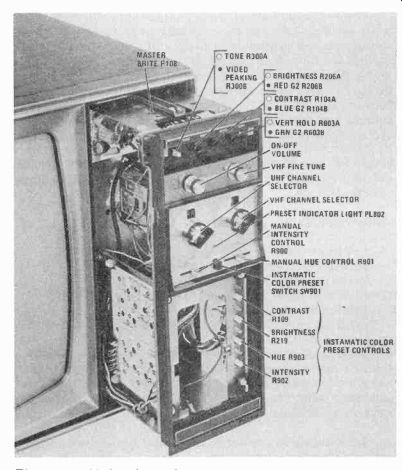
Fig. 4-6. Motorola's Quasar II front panel control locations, Chassis STS-934.
In actual receiver adjustment, you must find a cut-off point for each gun that will allow all three beams to extinguish at the same single low setting of the brightness control. Then the relative beam currents are controlled by advancing or retarding the various voltages at the grids and-or cathodes of the cathode ray tube, depending on the bias system used.
Sometimes these voltage controls are identified as background controls or they may be called gain controls, but both serve the same purpose: that of matching the beam currents to the various phosphors used over the range of both the brightness control and various voltage amplitudes of the received monochrome signal. Careful setup insures that the color signals will then be reproduced within receiver limitations. When the cathode ray tube is perhaps a bit low on output, there is often another potentiometer in the grid circuits of the newer cathode-fed picture tubes that can be adjusted to usually produce a lower cut-off voltage so the grid 2 voltages can be effective over large settings.
During general gray-scale adjustment procedures, the screen voltages are set to virtual cutoff and the control grids (or cathodes) are biased at some relative setting. To make the exercise more realistic, we'll use directions supplied by RCA for the CTC46 and CTC49 receivers (Fig. 4-7) as an example.
When these things are done you are ready for the usual combination static-dynamic convergence.
STATIC-DYNAMIC CONVERGENCE
The convergence adjustments are used to aim the CRT electron beams so that three pictures are superimposed over one another to produce a single unified image with maximum detail in monochrome transmissions and the necessary color mix in chroma transmissions. Static convergence is achieved by small adjustable permanent magnets in the external portions of the convergence yoke assembly (Figs. 4-2 and 4-8) several inches above each gun. Lines of force resulting from the static magnets reach the individual pole piece located within each gun. As each magnet is moved, the beams shift in the direction of the arrows in Fig. 4-8. The red and green beams, therefore, must be statically converged first, then the blue beam moved down to intersect the other two. Should the blue beam require side-by-side adjustment, there is also a blue lateral permanent magnet that moves the blue beam horizontally, left or right, as needed.
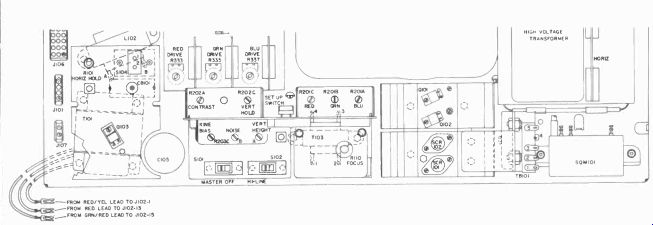
Fig. 4-7. RCA's CTC 49 rear panel setup adjustment locations.
Because of the geometry of the picture tube, beams deflected to areas other than the center of the screen are subject to further misconvergence because they have further to go to reach the screen. To correct the situation, varying electromagnetic fields are needed to converge the beams at all points on the screen. So further down in the yoke assembly, close to the neck of the CRT, are three electromagnets placed directly over the three RGB guns. The magnets consist of horseshoe-shaped ferrite cores about which are wound two pairs of coils in series. One pair corrects for misconvergence vertically and the other corrects for misconvergence horizontally. The correction fields are generated by a 60-Hz vertical AC voltage applied to one set of coils and a 15.75-kHz horizontal AC voltage fed to the other set of coils. Since the electron beams of the three guns are sweeping the CRT screen, they must pass through the magnetic fields set up across the pole pieces by each two pairs of coils. The fields change according to the AC applied as each bpm is deflected simultaneously at both horizontal and vertical scan rates, and are positioned on the raster at points proportional to the instantaneous strength of the varying magnetic field. Since the strength of the field changes as the three beams move across the face of the CRT, this method of active sweep correction is called dynamic convergence.
In some receivers, more than others, dynamic and then static adjustments must be made, sometimes alternately since there is interaction in most cases, to gain an acceptable overall degree of convergence without excessive fringing.
There's probably no such thing as perfect convergence, but an effort should be made to keep misconvergence at a minimum toward the center of the CRT and permit only small discontinuities at the top, bottom, and extreme left and right edges.
In this way, fringing can be checked, and most viewers will consider the adjustments satisfactory.
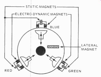
Fig. 4-8. Drawing of the convergence assembly placed over the three pole
pieces inside the CRT gun. The arrow shows the direction of beam movement.
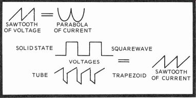
Fig. 4-9. Dynamic convergence currents developed by voltages from the horizontal
output circuits.
Dynamic Convergence Controls
In dealing with output and convergence circuits, remember two important rules (Fig. 4-9): a sawtooth of voltage through an inductor produces a parabola of current, and a squarewave (or a trapezoid) of voltage produces a sawtooth of current. These are worth remembering because you are dealing with exactly such currents in the process of dynamic convergence.
Many of the older dynamic convergence assemblies had an even dozen resistor and coil controls mounted on an individual printed circuit board, and there were four separate controls called vertical amplitude, vertical tilt, horizontal amplitude, and horizontal tilt for each of the three colors.
Today, reds and greens (top, bottom, right side, left side) work together, while the blue controls are separate potentiometers or a coil on the bottom. Because of these red-green groupings and blue independents, dynamic convergence is considerably easier with the new system and can be done in much less time.
The principle of both systems, nonetheless, is the same.
The vertical and horizontal output tubes or transistors supply a sawtooth voltage that translates into a parabolic current in the appropriate dynamic convergence network. These coils are resistive as well as inductive, however, and the sawtooth voltage must sometimes be modified (by a diode) to produce a shaped parabolic current. Probably the best example to consider is the RCA CTC 40-44 dynamic convergence operation.
Vertical Convergence
The vertical convergence circuitry generates the required parabolic current waveshape by shaping a partially integrated vertical sawtooth voltage. A simplified schematic is shown in Fig. 4-10.
The vertical sawtooth voltage is developed across R126, a 39-ohm resistor connected in series with the vertical output transformer primary and B+. The vertical convergence circuit directs current from this sawtooth voltage source through two paths. The path used to converge the upper half of the picture exists through C802, differential resistors R804 and R805, the red and green vertical convergence coils, diode CR803, to B+. Capacitor C802 and resistors R802 and 803 form a shaping circuit in which the values are chosen for optimum convergence. The other path is used to converge the lower half of the picture. During this time, diode CR803 is no longer conducting and the current flows through R803, differential resistor R805, the convergence coils, amplitude resistor R808, the shaping network CR801, CR802, R801 and capacitor C801.
The amplitude controls, R803 and R808, provide control over the amount of correction of vertical lines, while differential controls R804 and R805 correct the error in horizontal lines at the top and bottom of the scan.
The blue vertical convergence circuitry, simplified in Fig. 4-11, provides for vertical convergence of the blue horizontal lines as the vertical scan progresses. The correction current required is provided by the same voltage source used to converge the upper and lower halves of the picture in the case of red-green. The blue circuitry provides correction of either polarity as well as of variable magnitude.
Horizontal Convergence
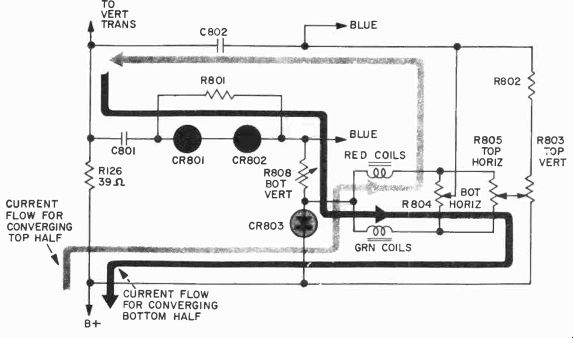
Fig. 4-10. RCA CTC 40 vertical convergence circuit.
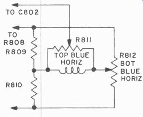
Fig. 4-11. RCA CTC 40 blue convergence circuitry.
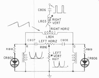
Fig. 4-12. RCA CTC 40 R-G horizontal convergence circuit.
A simplified schematic of the horizontal convergence circuitry is shown in Fig. 4-12. Pulses at a horizontal rate are integrated by L803, R816, R817, C807 and C808, forming a sawtooth voltage waveform which is applied to the red and green horizontal convergence coil windings. This sawtooth voltage waveshape creates the necessary parabolic current waveform in the coils. Clamping circuits, consisting of CR805, CR806 and associated resistors, act to rectify a portion of the circulating current, thereby adding a DC component to the convergence current waveform. This DC component insures that convergence coil current is substantially zero when the beam is in the center of its scan, thus easing setup procedures.
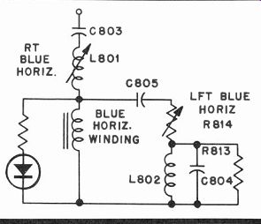
Fig. 4-13. RCA CTC 40 blue horizontal convergence circuit.
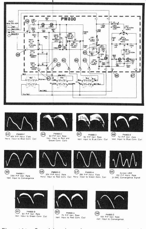
Fig. 4-14. Complete dynamic convergence board schematic with the convergence
yoke assembly coils on the bottom (CTC40-44). Refer to the waveforms for drive
and resulting circuit characteristics.
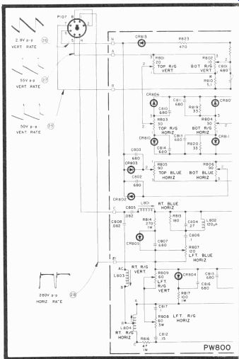
Fig. 4-15
Components L804 and R816 allow different currents to flow in the red and green horizontal convergence coil windings.
This "differential" current flow is to correct for errors in horizontal lines on the left and right sides of the scan.
The blue horizontal convergence circuitry (Fig. 4-13) operates on the same principle as the red and green horizontal convergence circuitry just described. However, a waveshaping network, consisting of L802, C804, and R813, adds a second-harmonic sine wave of the proper amplitude to the blue convergence coil current. The resulting waveshape optimizes the blue convergence.
Fig. 4-14 is the complete convergence board schematic, showing the entire circuit, with red, blue, and green electro dynamic convergence coils at the bottom outside the heavy dotted line. The "balloon" numbers, 58 through 68, refer to the waveforms, which indicate the p-p voltages, since the current in each case is very small.
The CTC 46 version of this convergence assembly (Fig. 4 15) has some changes in the top and bottom R-G horizontal and vertical adjustment sections, principally in component arrangements, plus the addition of almost half again as many diodes. This seems to mean more control over the convergence circuits, with less interaction among the various adjustments. Diodes will shunt, guide, block, and rectify AC voltages, depending on the circuit positions and forward (anode-to-cathode) bias. In this newer arrangement, the red and green convergence portions parallel the blue in the top and bottom red-green convergence, while top and bottom blue convergence adjustments are simply in parallel with the blue convergence yoke coils. The various potentiometers deter mine current flow into the several portions of the convergence coil windings.
When troubleshooting such a circuit, your only recourse is careful waveform analysis with an oscilloscope, bearing in mind that there are many more failures among diodes and capacitors in this type of PCB assembly than with other passive parts. In vacuum tube receivers, cores have often stuck in the right vertical and horizontal coils because of heat.
Then, either the core was freed and probably replaced by any means handy, or an entirely new tunable coil was substituted for the bad one. In solid-state receiver convergence circuits, diode failures will probably predominate, especially if these semiconductors are even slightly underrated for either for ward current flow or PIV (allowable peak inverse voltage that destroys the diode when exceeded).
The latest Zenith versions of the original 4B25C19 receiver have a rather simplified but highly effective convergence assembly (Fig. 4-16), using but four diodes and the usual number of coils and potentiometers in the same general type of arrangement for dynamic convergence adjustments.
Convergence assembly iron core series coils are shown in the center of the diagram, with the 9-pin connecting plug on the top right.
Two-Pole Convergence
Some small screen receivers (Fig. 4-17) have a 2-pole convergence system where the blue controls act as in the standard 3-pole system. There is a red-green lateral magnet that moves the red and green beams in opposite directions until the two beams cross. At this point, you have RG convergence and the correct control setting. The red-green horizontal and the red-green vertical balance controls are added to balance both magnetic fields for top and bottom and right-left sides so that each is supplied equal parabolic waveshape correction. This is especially true at the beginning and ending of the vertical and horizontal sweeps. The amplitude controls, then, are simply the amount of correction applied, while tilt is the placement of correction applied.
In setting up and converging the average receiver, the new ones are rarely touched unless there has been meddling or a new cathode ray tube has to be installed. Occasionally on new products, the factories have "people problems," but this is normally corrected promptly after a new chassis' initial run.
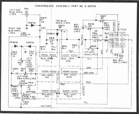
Fig. 4-16. Zenith 4B25C19 series dynamic convergence board schematic.
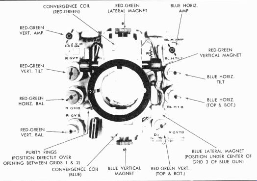
Fig. 4.17. View of the two static and dynamic convergence components on the
CRT neck in Zenith's 14CC14 through 16 chassis.
Notice the red-green lateral magnet and different control terminology.
QUESTIONS
1. What makes color fringing?
2. Color impurities are caused by 9
3. Deflection yokes are positioned where at the start of purity adjustments?
4. Do you adjust static convergence initially before or after purity adjustments?
5. Do you use a dot generator before or after initial purity adjustments?
6. Why do you degauss a receiver?
7. When you spread the purity tabs, the magnetic field strength decreases, true or false?
8. What percentage of new color sets have automatic degaussing?
9. In gray-scale adjustment, your first adjustment is selecting ?
10. Vertical convergence circuitry generates what kind of current waveshape?
11. Horizontal convergences form a waveform?
12. What type convergence assemblies are found in small screen receivers?
Next: Tuners, Video IFs & AFTs
Also see:
TV Antennas and Transmission lines
Air Time--An Intro to Television Broadcasting
TV and Radio Tube Troubles (1958)