Since many of these circuits were initially discussed in Section 1, it is necessary to cover here only those portions that have specific significance, with additional emphasis on the evolution of signal processing by vacuum tubes, discrete transistors and integrated circuits.
Fig. 5-1 is a system block diagram in which the UHF tuner output is plugged directly into the VHF tuner, where sections of the lower band tuner function as additional RF amplifiers to boost Channels 14 through 83 and pass them at IF frequencies to the video IFs. Of course, if the local UHF or VHF oscillator is off-frequency and the automatic fine tuning (AFT) circuit is engaged, the AFT (within limits) puts the local oscillator(s) back on frequency so that the 42.17-MHz chroma and 45.75-MHz video carriers are both somewhere near the mid (half power)-points on opposite sides of the response curve (Fig. 5-2) . The typical IF response has a flat top and sloping sides, depending on trapping and the design characteristics of the various IF stages.
You will notice that we show three IF amplifiers in Fig. 5-1. Some tube receivers have two IFs and some transistorized sets have four IFs, but most receivers have a 3-tube or transistor IF system. Most IFs are stagger tuned (each circuit tuned to a slightly different frequency) to achieve the desired gain and bandpass.
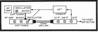
Fig. 5-1. Familiar block diagram of a tuner, AFT and IF system.
It is imperative you know and understand video IF alignment waveforms completely if you expect to deal effectively with color television. A "sloppy Joe" monochrome response may satisfy uncritical mothers with cataracts, but the average wage-earner is going to expect a substantial return for his $600 to $800 investment (if he buys a top-rated receiver).
Fig. 5-2. Typical tube and transistor IF and RF response curves (they're often similar), showing chroma and video carrier positions, plus two basic trap frequencies. Heavy line is the vacuum tube receiver curve, while the dashed line is a semiconductor receiver IF waveform. Center frequency for all IF waveforms is 44.25 MHz.
TUNERS
The VHF tuner simply selects any one of 12 channels between 54 and 216 MHz. The local oscillator operates 45.75 MHz above the video carrier, and this results in a center 44.25-MHz beat different that becomes the mid-video IF frequency.
The response curve of any tuner, of course, is very similar in appearance to the vacuum tube IF response, with the sound and video carriers separated on the top by the standard 4.5-MHz difference (the sound carrier is always the higher frequency). At Channel 2, the picture carrier is 55.25 MHz, while the sound carrier is 59.75 MHz. On Channel 13, the picture carrier is 211.25 MHz and the sound carrier 215.75 MHz.
This applies equally to the UHF spectrum where the 4.5-MHz frequency difference remains the same.
Vacuum Tube Switch Tuners
The RCA KRK 120T UHF tuner (bottom portion) Fig. 5-3, uses a semiconductor, but then all UHF tuners have been transistorized for a number of years. The UHF input passes through a 300-ohm center-tapped balanced coil. The desired signal is selected by reactive gang-tuned capacitors C2, C4 and...
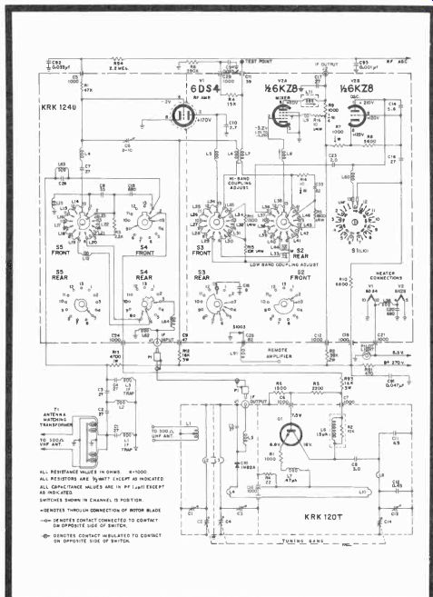
Fig. 5-3. Schematic of RCA's KRK 124U, W-KRK120T tuner used in CTC25 series
receivers.
...C14 that resonate with coils L2, L3 and L8. C1, C3, and C13 are variable tuner trimmers. Coils L4 and L10 are inductive couplers for oscillator Q1 and mixer diode CR1, while L6, shunted by R2, is part of the damped load, along with R93 from the power supply. R5 and R6 are base biasing resistors (voltage dividers) for Q1 which, again, oscillates at 45.75 MHz above the video carriers in the 470- to 890-MHz UHF band.
Diode CR1 mixes the incoming RF with the oscillator signal.
The beat difference is slightly filtered by C5 and passed to the Channel 1 position of the detented VHF tuner.
The KRK124U VHF tuner accepts this IF signal and the V1 ceramic 6DS4 RF amplifier becomes a UHF IF amplifier along with the 6KZ8 mixer. The VHF oscillator is cutoff from B+ in the Channel 1 UHF position. Since the UHF IF output already has some slight filtering, IF feedback would be pretty difficult, and the tuner sees only frequencies at 470 MHz and above. Heavy IF filtering and moderate high-pass filtering is hardly needed.
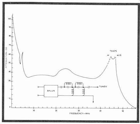
Fig. 5-4. Balun and input filter attenuation in db as a function of frequency
in MHz. Notice that undesirable signal rejection from 0 to 50 MHz is no less
than 32 db and more than 50 db at the traps. (Courtesy Dave Carlson, RCA).
When the UHF tuner is not used and the VHF tuner is fully supplied with input signals and DC operating voltages, the input circuit and accompanying filtering become quite important (Fig. 5-4). VHF signals are applied through the antenna matching transformer (T1), called a balun (balanced to-unbalanced), that transforms the 300-ohm antenna and transmission line impedance to a 75-ohm input for the RF amplifier. C1, L1, C4 and L3 form tuned IF traps that prevent IF frequencies from radiating outward from the receiver to the antenna and also block frequencies around 40-plus MHz and below from entering the tuner. At the same time, high pass T filter (C2, C3, and L2) also aids in suppressing incoming signals below 54 MHz. (An 88- to 108-MHz FM trap might be something of a variable notch-type filter for specific passband rejection.) A graph of balun and high-pass filtering is shown in Fig. 5-4. Minimum rejection is 32 db at 50 MHz.
The signal input now passes through S4 and S5 to the series switched inductances on the S5 front wafer, which by shorting action selects the correct reactances and time constants so that the RF amplifier sees only the 6-MHz band of frequencies to which the channel selector is tuned. The signal is passed to V1 where the amplifier RF output develops across load coil L5 and S3 (front). L6-L7 mutually couple the high-band in formation, while L33 and L44 adjust and pass the low-band signals through S2 (front) to the grid of V2A (6KZ8 mixer).
This tube uses a common +270-volt DC supply for the screen grid and plate, separated and decoupled by two coils (one peaking) and a pair of current-limiting and voltage-dropping resistors. The tuned local oscillator, as stated, operates at 45.75 MHz above the video carrier, and this signal is also put to the mixer grid through L36, L37 or S2 (rear) and L8. The beat difference is the 45-MHz IF video carrier that is now passed through IF output J2 to the IF amplifiers. The DC supply reaches the local VHF oscillator through S1 and L60, an AC blocking reactance. Additional switch coils determine the frequency (or repetition rate) of the local oscillator (V2B) in conjunction with C14, C]6 and the associated resistors.
Transistorized Turret Tuners
Although the basic function of any tuner is to select the desired RF frequency and convert it into separate video and audio carriers, the transition from tube to solid-state tuners has been rather long and sometimes painful. All sorts of common-emitter, common-base, and cascode RF con figurations have been tried, some with good, mediocre and poor results and others not worth using, until rather recently.
The story is pretty well told in Figs. 5-5 through 5-8.
Any tuner must have certain creditable performance characteristics that include satisfactory low noise figures, adequate 6-MHz bandpass with good adjacent-channel rejection, a relatively broad fine tuning range, little drift, tolerable input impedances, low standing wave ratios (SWR), limited cross modulation (there is always some), good gain, mechanical ruggedness, ease of servicing, acceptable low local oscillator radiation and noise-preventive shielding.
The most difficult design part of any tuner is the RF amplifier, where gain, noise, SWR and cross modulation are all wrapped up in a single (or cascode) device that determines much of the overall characteristics of the tuner. Fig. 5-5 amply illustrates the effects of cross modulation (where two strong signals force the generation of additional RF signals by modulating one on the other) in terms of gain reduction for at least the unproductive beginning with the unwanted sum and difference beats. The graph specifies the percentage test figure as 1 percent.
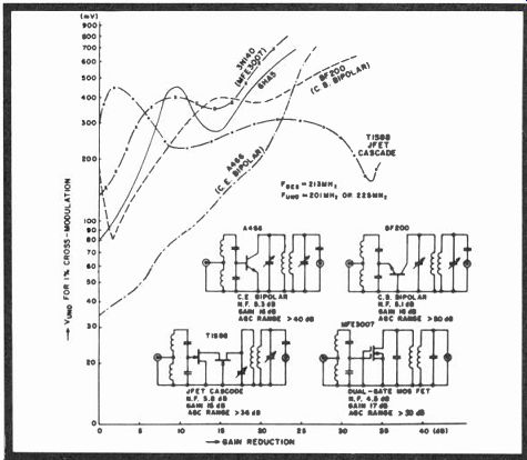
Fig. 5-5. Cross modulation curves. (Courtesy Frank Hadrick, Zenith)
The A466 common-emitter bipolar begins cross modulation at 35 millivolts and climbs steadily, with a gain reduction up to 25 or so db to 700 millivolts (0.7 volt). Without taking into account other factors, the raw standing wave ratio
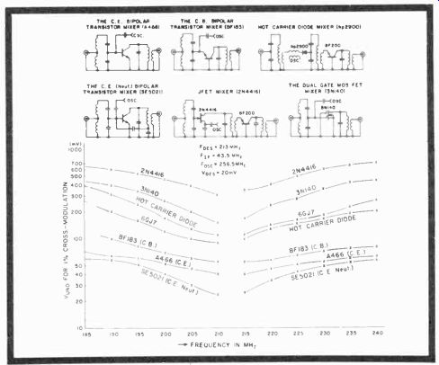
Fig. 5-6. Mixer cross modulation curves. (Courtesy Frank Hadrick, Zenith)
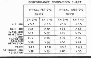
Fig. 5-7. Performance comparison chart with composite data.
is Emax divided by E_min, or 700 divided by 35-a rather un desirable SWR of 20. The BF200 common-base bipolar looks somewhat better, since cross modulation doesn't begin until about 180 millivolts, dips to 80, but still extends to 600 at the 25 db down point-a more modest SWR of 8.75.
Next, a junction field-effect (TIS88) transistor was tried and 1-percent cross modulation began at 300 millivolts, full gain, then increased to 150 my at about 2 db reduction, and fell thereafter down to about 150 my at 35 db gain reduction. This raw SWR amounts to a 3:1 figure over a much wider range, probably much more than is needed.
The final amplifier tried was a dual-gate metal oxide semiconductor that produced a gain of 17 db with an AGC range of better than 50 db-a rather marked improvement over even the JFET, and better than the common-base BF200 bipolar transistor. The MOSFET MFE3007 began 1-percent cross modulation at 150 millivolts and increased to about 700 at the 25 db gain-loss point, an overall SWR in this case of 4.67:1.
Observe how this compares with the curve for the 6HA5 tube that starts at 80 millivolts and finishes about 650.
The JFET looks good, but even in the cascode (drain tied to source) configuration, its noise factor is 5.8 (the highest), its gain is less, and AGC range is limited to about 36 db. So the dual gate MOSFET, obviously, wins with a low noise figure of 4.5 db, a higher gain, and a variable AGC tolerance of more than 50 db. Even better figures than the hot, current-consuming 6HA5 vacuum tube that has been an industry standard for some time.
Next to be developed was Zenith's mixer, and Fig. 5-6 shows the 1-percent cross modulation figures, in millivolts as usual, but this time as a function of frequency in MHz. The tube comparison was a 6GJ7, another good performer. Test frequencies began at 185 MHz and continued to 240 MHz, since the mixer operates at these frequencies that are apparently more critical in the upper channels. At any rate, the same types of configurations as used in the RF amplifier tests were tried, including hot carrier diodes, yet the results proved pretty much the same. The 2N4416 JFET was good, but overall performance was better with the dual gate MOSFET and, as you can see by comparison, it performed better than the 6GJ7 standard vacuum tube mixer. So in digital as well as analog (linear) applications, MOSFETs and CMOS (complementary MOSFETs) are now becoming the leaders in many types of signal processing, especially since most now have protection against electrostatic gate punch through.
A final comparison of FET and tube-type tuners is shown in Fig. 5-7, beginning with noise figures and ending with un wanted frequency rejection. Arrows pointing toward a number designate "greater than" and arrows in the opposite direction mean "less than." As you can see, only in db gain does the tube type have any small advantage over the FET, and those differences are minuscule.
The completed unit is shown in Fig. 5-8, and has been designated Zenith's 175-1800 Series solid-state tuner. The three...
Fig. 5-8. Zenith's 175-1800 solid-state Gold Video Guard VHF turret tuner
with two MOSFETs and a bipolar oscillator.
Fig. 5-9. UHF-VHF bandswitch, cams, and tuning resistors in Zenith’ s all-varactor
tuner.
...strips at the top of the schematic represent the actual rotating coils, where Channel 1 is the UHF input and Channels 7-13 and 2-6 are the RF-antenna signal receiving portions. Other coils tune the converter and oscillator so that the entire tuner responds to the incoming 54 to 216 MHz frequencies.
Signals come in through a 75-ohm input and across substantial traps, through the antenna coils to the G1 gate, which is slightly biased by 2.2-megohm R4 and AGC controlled through guide diode Xl. Q1 amplifies the incoming microvolt-level signals under varying delayed AGC control, depending on signal strength, and puts out a voltage through Terminal 8, which is inductively coupled to gate 1 of the mixer (Q2).
Again, G2 of this MOSFET is the more strongly biased electrode, while G1 receives both the amplified RF signal and the signal from the oscillator, which is applied to Q2 through the coil coupling between Terminals 11 and 12. Automatic fine tuning (when operating) controls the oscillator through varactor X3 when the video IF 45.75-MHz frequency varies from its midpoint position on the slope of the IF response curve. This process is repeated from channel to channel as the turret is rotated, inserting various inductive tuning and coupling for the three stages. Notice the many feed-through capacitances along the common line of the tuner's lower "ground" edge. They are used both as filters and AC grounds and are quite effective (C7 through C12, for instance).
A UHF Varactor Tuner
The varactor is a special back biased diode that operates like a capacitor, except that it is entirely DC voltage con trolled...in this instance between 0.5 to +28 volts from a regulated supply source and energized by a carefully con trolled voltage drop across a precision resistor. The tuning resistors, levers, and gear train, shown in Fig. 5-9, are part of Zenith's varactor VHF-UHF tuners featured in the deluxe receivers. Each tuner resistor is separately adjustable (programmed), and when the tuner is rotated to an individual channel, a discrete voltage develops across one of the resistors and tells the diode( s) what capacitance it should represent, thereby tuning the RF amplifier and local oscillator. The VHF tuner, of course, operates on the same general principle, and could well be included here, except that we discuss next a special printed-circuit tuner built along the same lines.
This tuner (Fig. 5-10) can accept either 72- or 300-ohm inputs, with a balun mounted on the antenna terminal board itself, rather than on the tuner as has been done in the past. A second innovation is that J102 is both the 75-ohm VHF and UHF antenna input. The VHF is separated from the UHF signal by C101 and L101, which operate as a low-pass filter, while C102 couples the UHF directly into the Q101 RF amplifier tuning inductor.
Since the UHF tuner has neither low nor high bands, but a single 470 to 890 MHz frequency range, programmed voltages to varactors CR101, CR102, CR103 and CR104, in conjunction with inductors L102, L104, L108 and L110 control both the RF amplifier channel selection and the repetition rate of the common-base oscillator. RF and oscillator signals are passed through mixer diode CR105 and L110 to the base of the common emitter amplifier, Q103, which feeds the IF to the VHF tuner. Tunable capacitors CX101 (high-end-of-band tracking) through CX103 are additional tuning resonances of the manual variety. The same is true of L103 (low-end-of-band tracking), L106, L109, and L111. L112 is fixed frequency only.
Printed-Circuit Varactor VHF Tuner
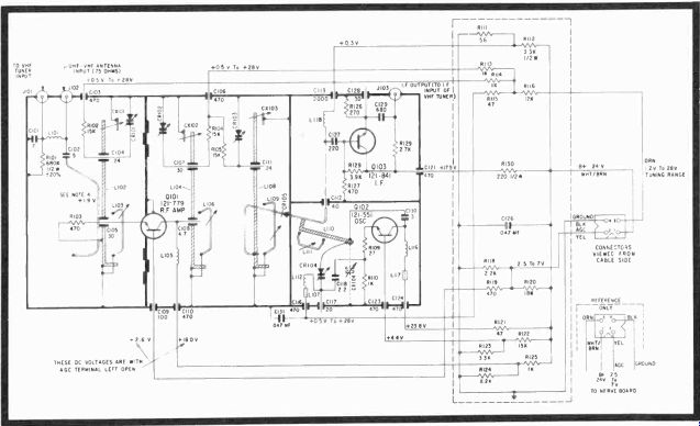
Fig. 5-10. Schematic of Zenith's varactor UHF tuner using a grounded-base
AGC-controlled RF bipolar input.
This tuner was developed by Motorola Semiconductor, Phoenix (Ben Scott, Applications), to demonstrate the use of their MV3102, MV3141 varactor diodes and MPN3401, MPN 3402 pin switching diodes. The tuner has both a high and a low band, with diodes D2 (five of them) either being reversed or forward biased. The diode bias level and inductors L1, L4, L7 through L10 change the frequency response of the tuned circuits. Thereafter, the D1 series of varactors are programmed by tunable resistors.
Again, a MOSFET is used as the RF amplifier because the tuner noise figure, a low degree of cross modulation, power gain, small VSWR, good AGC range, and relative changes of input impedance with AGC all depend on it. Here Motorola uses its MPF121, which has both low input and output capacitance, a common-source typical noise figure of 2.6 db, and a minimum common-source power gain of 17.
The mixer is a bipolar cascode type with the first collector DC coupled to the second emitter and a full 24 volts DC across both transistors. The first transistor circuit, obviously, is a common-emitter type, while the second is common-base. This configuration was used, because of the extra gain it produces, and the excellent isolation provided between input and output.
The oscillator must have a stable, strong output between 101 MHz and 257 MHz, and the selection of the tuning diode is critical because the oscillator may swing the diode into for ward conduction with small bias voltages and radically change frequency. An MPS-H11 is used as the oscillator. Since the varactor diode's capacitance determines many of the passive RLC component values, a designer has to limit himself to the smallest reliable tuning voltage. This will lower the Q at small bias voltages and reduce the possibility of intermodulation distortion where two different frequency sine waves are injected and the power output is measured with no clipping. Fig. 5-12 lists Motorola's findings of this tuner's performance per channel.
The foregoing should give you a comprehensive introduction to the various types of tuners, their electrical and mechanical features, progress over the last several years, and some of the stiff design hurdles that engineering must always overcome. All these factors are good general lessons that can contribute considerably to the overall understanding of any tuner's functions and desirable characteristics.
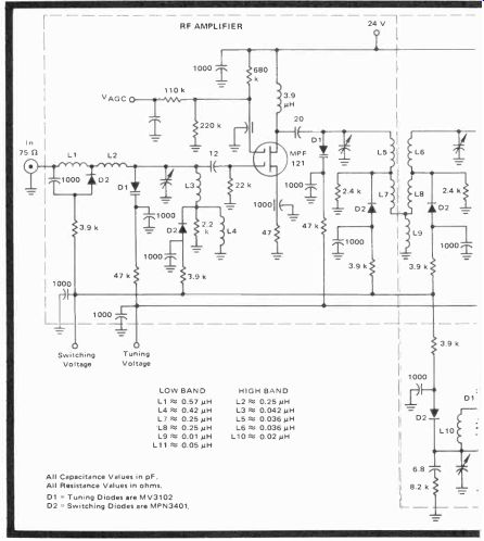
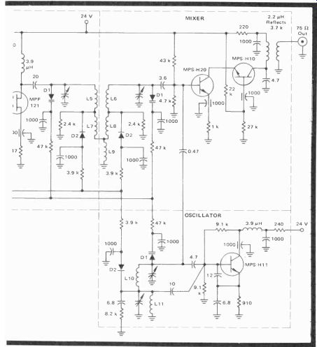
Fig. 5-11. Schematic of the Motorola printed circuit tuner using varactors,
and pin diodes. All Capacitance Values in pF.
All Resistance Values in ohms.
D1 = Tuning Diodes are MV3102
D2 = Switching Diodes are MPN3401.
VIDEO IFs
The function of these variously numbered stages (although three is now typical) is to accept center frequency signals of approximately 44.25 MHz, which contain the video carrier at 45.75 MHz, audio carrier at 41.25 MHz, and the chroma carrier at 42.17 MHz, and process these signals with sufficient gain and bandpass.
How these IF strips are designed, shielded, controlled and supplied determines much of the operating efficiency of the remainder of the set. Luminance and sync information should fill the AM passband up to about 3.5 MHz. FM audio is derived from the 4.5 MHz heterodyne heat between the eventually trapped 41.25-MHz audio carrier and the 45.75-MHz video carrier. Chroma is clustered at the 0.5-MHz sum and difference frequencies about the suppressed chroma subcarrier at 3.6 MHz. Video IF strips often develop a tilt that must be compensated by a reverse, equalizing tilt in the chroma amplifiers.
Meanwhile, have you often wondered what happened to the wondrous 4.2-MHz video bandpass that some writers still mention? For many years, such broad response hasn't existed. You may think you're seeing something like it, but appearances are deceiving. The practical limit to video...
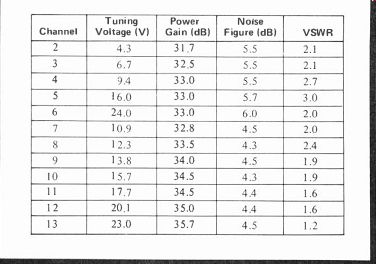
Fig. 5-12. Printed-circuit tuner performance per channel.
...bandpass today is little more than 3.5 MHz. On a monochrome receiver, for instance, if the video response exceeded this bandwidth, color around the 3.6-MHz carrier frequency would immediately appear as a disagreeable herringbone background interference that most people wouldn't tolerate.
On the other hand, if a color receiver went much beyond 3.5 MHz, the clash between color and monochrome luminance intelligence would actually cause chroma desaturation, and you'd have washed-out colors. So bandwidth and picture resolution are really a series of manufacturing compromises that produce the "best overall picture." Before we get into the actual IF discussion, the trap and carrier frequencies in Table 5-1 should be helpful in understanding why certain circuits are designed the way they are. Almost all color receivers have at least seven of these eight IF traps and sideband-carriers, while Motorola's Original Quasar has the eighth-the 35.25-MHz upper-adjacent sound trap. You would do well to commit these important frequencies to memory. Remember, the video-chroma carriers and sidebands all appear on the sides of any swept IF response curve, while the traps determine rolloff characteristics and are all situated along the baseline, just like the 41.25-MHz audio-carrier trap shown in Fig. 5-11.
Carriers (MHz) and Sidebands 41.67-Lower chroma sideband 42.17-Chroma subcarrier 42.67-Upper chroma sideband 45.75-Video carrier Traps (MHz) 35.25-Upper adjacent sound trap 39.75-Upper adjacent pix. carrier 41.25-Sound carrier 47.25-Lower adjacent sound carrier

Table 5-1. IF trap and carrier frequencies.
Vacuum Tube Video IFs
In Fig. 5-14, coming through P101 are the video IF and sound IF signals, where the latter is partially trapped by lower adjacent-sound carrier trap L301-C302, C303, and sound reject adjust R301. Video information and 41.25-MHz audio are then passed through the impedance matching and coupling first IF transformer to the grid of the 6JH6 first IF. Here the DC voltage will be 0 if there are no signals and somewhat negative if there are incoming signals. L302, C304, L308 and C310 are LC filament filters. The AGC control voltage is applied to the first and second IF stages through the transformer secondaries. The AGC voltage arrives at PW300 terminal E.
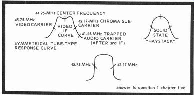
Fig. 5-13. Solid-state video IF curve shown side by side with tube IF curve,
indicating center IF, chroma, video, and sound markers.
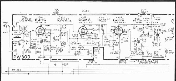
Fig. 5-14. Typical tube-type video IF circuits.
The 6JH6 is a semi-remote cutoff pentode used in gain controlled video IF stages and is an offspring of the old 6BZ6.
Open transconductance is 8,000 micromhos, but with a control grid voltage of-4.5 volts, it drops to between 400 and 900 micromhos.
Terminal F is the 405-volt B+ supply point and there follows a series of dropping resistors and filter capacitors from the output of the second IF, straight through to the grid of the first IF, including resistors R308, R306, R305, etc., with dividers R307, R311 and others. And although T301, T302, and T303 show no internal cores or variable arrows, you can be sure at least one section can be tuned. The second IF amplifier (6GM6) is another semi-remote cutoff pentode with a trans conductance of 13,000 micromhos. It's cathode is at virtually the same potential as V301's plate, so V302 is called a "stacked" amplifier and, because of its high cathode voltage, the plate voltage can go to 340 volts (340-184 or 156), and deliver a very high output swing with reference to ground.
Signals out of V302 are transformer (T303) coupled into the grid of V303, a sharp cutoff pentode with a high trans-conductance at low B+ voltages. The cathode of this tube is referenced directly to ground through a 180-ohm resistor bypassed by C315 to remove signal degeneration and permit maximum DC current flow plus AC tube operation. Bypasses for the screens and suppressors of these tubes also prevent extraneous signals from forming on the electrodes, which would cause undesirable tube degeneration.
T304, following V303, is both the third IF transformer and the 41.25-MHz sound carrier trap. R315 is a second sound reject potentiometer, shunting the reactive impedance of L305, a 12 microhenry peaking coil. L309 is another coil, but this time it is called an RF choke since it is just before the CR301 sound detector. CR301 picks up the sound on a new FM beat carrier of 4.5 MHz, the difference between the 45.75-MHz video carrier and the 41.25-MHz sound carrier. From the sound detector, the 4.5-MHz signal goes to the sound IF.
As a further precaution that no sound reaches the video circuits, a 4.5-MHz sound trap (L306) follows video detector CR302. With the video and sync signals ready for further processing, information now goes through peaking coil L307 to the succeeding circuits for sync, chroma, and video (luminance) separation.
TRANSISTOR VIDEO IF STRIP
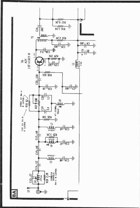
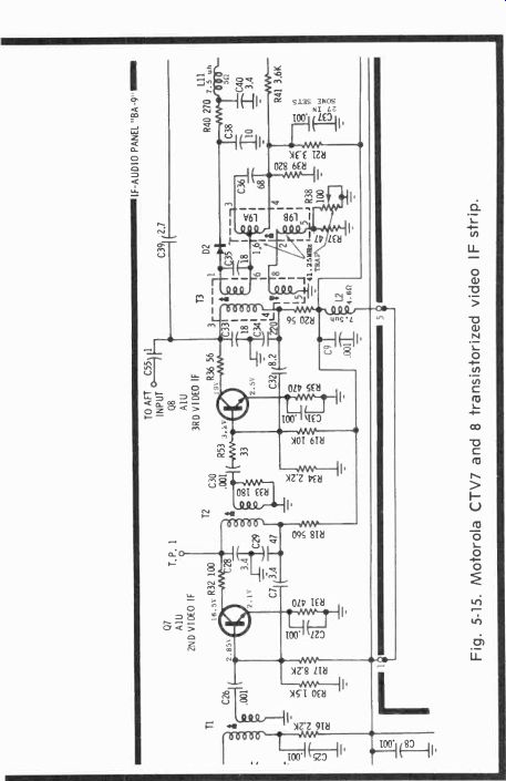
Fig. 5-15. Motorola CTV7 and 8 transistorized video IF strip.
From the world of vacuum tubes to that of transistors isn't such an enormous transition as one might expect (Fig. 5-15). Yet, the considerably lower voltage power supplies (in this instance, 20 volts vs 405) and the relatively small currents, plus plug-board flexibility, makes the modular type solid-state chassis quite attractive from many standpoints. With transistors, impedances are lower, of course, and this usually increases noise immunity, but inductor and capacitance coupling between IF stages still exists as it did almost 20 years ago.
The RLC parallel and L4 tuned resonant circuit is an input band-shaping circuit and is tuned for best video carrier response at 45.75 MHz on the half power point of the response curve. L5 is a low pass aid filter, part of a pi network, along with C13 and C15, for the 39.75-MHz upper-adjacent picture carrier trap that resonates with C16. R25 is a damper resistor.
L7 and C18 are identical to L5 and C14, and form what now could be called a pi network for higher frequency attenuation.
The L7 and C18 trap is followed by another pi-type attenuator, which is the 47.25-MHz lower-adjacent sound carrier trap; R27 is a balance adjust control. Notice, again, that the sound carrier itself is not attenuated until the 4.5-MHz intercarrier beat is picked up by the audio circuits.
Forward AGC is applied to the first video IF through R28 and, with large incoming signals, the Q6 current flow is reduced with overbias and so decreases the signal output. The emitters of all three transistors are resistively biased for single battery operation and the most stable operating points, R30 and R17 being base divider examples. Here, for instance, you have a 20-volt DC supply. So base bias amounts to E x 2.2K divided by (2.2K + 8.2K) or 4.23 volts, less the voltage dropped from the transistor base to emitter, since the potential difference of 0.75 volts between the base and emitter shows the transistor is conducting.
Capacitors C28 and C29 are stabilizing shunts, and C7 is a little degenerative feedback path that, with C29, is also a capacitive divider. C7 also helps control the base of the second video IF, since it is not AGC controlled. R33 (across the secondary of T2) is an anti-ringing and stabilizing resistor, while L2 (off the lower primary of T3) is a choke to keep IF frequencies from the DC supply. T3 is the third IF transformer with a 41.25-MHz sound trap in its secondary, adjusted by R38 for best trap notch. The automatic fine tuning signal sample and the sound signal are taken from the collector of the third IF just before the primary of double-tuned T3. Diode D2 is the video detector diode, followed by a small filter and peaking coil L11.
Integrated Circuit Video IF RCA unveiled the first all-integrated circuit video IF amplifier. It was used in the first U.S. 110-degree 18-inch thin picture tube color receiver, the CTC49. In addition to IF amplifiers, the CA3068 has a noise limiter, keyed AGC, buffered AFT output, sound carrier detection, amplification, with zener diode regulation-quite a subsystem for a little 20-pin integrated circuit that can dissipate 600 milliwatts! Fig. 5-16 is a block diagram of the system with power supply and pass transistor between pins 15 and 18, plus IF transformers at the top and left of the illustration. Signals come in through double-tuned bandpass shaper T1 to the first IF amplifier, which drives the AGC, additional IF stages, video amplifiers and sound channels. The outputs, of course, are sound and video, with separate RF AGC voltage for the tuner. Fig. 5-17 is a photo of the complete module.
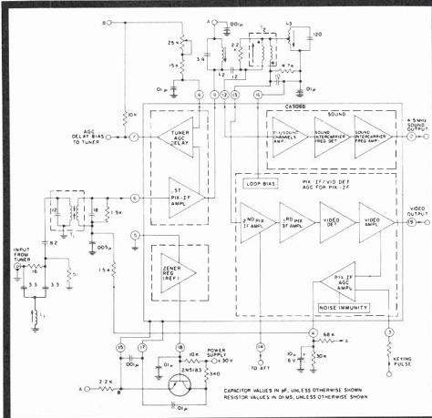
Fig. 5-16. Block diagram of the RCA CA3068 IC video IF, showing internal
functions and external components.
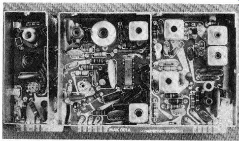
Fig. 5-17. Photo of the entire MAK I F module with CA3068 and CA3064 IF and
AFT ICs located in the second and third compartments from the left. (Courtesy
Tom Bradshaw) A simplified schematic of the CA3068 appears in Fig. 5-18.
Darlington stages Q19 and Q20 drive parallel-connected amplifier transistors Q3 and Q4. With increased input, Q1's conduction is decreased, and Q4 then is brought into operation by the signal input at the Q9 emitter. With Q1 cutting off, less of a hold is applied to the base of zener clamped Q21, and this transistor turns on Q5 for an increased negative output to control the tuner's RF amplifier. Q21 also supplies drive for Q14.
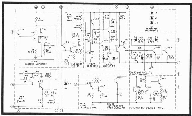
Fig- 5-18. Simplified schematic of RCA's CAJO68 video IF.
The transformer tuned wideband IF amplifier includes emitter follower Q6, amplifier Q7 and amplifier Q8, with 45.75-
MHz signals passing through pin 14 to the automatic fine tuning and full video to the detector. Q8 drives Q22, which is regulated and biased by current source Q9 and the current flowing through the emitter of Q23. R19 and C2 combine as a peak detector with selected time constants that do not introduce differential chroma phase errors nor result in amplitude distortion. Video amplifier Q24 receives DC bias and signals from the video detector and transmits them to amplifiers Q12 and Q25.
Transistor Q12, when in conduction, determines white level for video output terminal 19. To prevent its conduction when there is no video, the emitters of Q10 and Q24 must have the same DC potential and similar currents. When this hap pens, Q11 absorbs all the current from Q24 and there is no flow through D3 or Q12. But when video information is present, the current through Q24 increases in direct proportion to the signal, the current in Q10 is fixed, and Q12 fires, permitting video output at terminal 19. With a further increase in video signal, the DC at the base of Q12 increases, there is a DC decrease at the base of Q25 until the base of Q25 drops toward ground and further signal increases are "bottomed" or clipped.
With a normal signal, Q25 transmits the composite waveform with sync tips keying AGC amplifier Q13, which also affects Q14. When the voltage for Q13's base begins to fall below 0.8 volt, the keying current is diverted increasingly into diode D4. During this time, Q14 discharges an external 10-mfd capacitor, usually connected to terminal 4, at a rate proportional to the base current entering Q14, and this varies the AGC voltage inversely and proportionately.
For noise immunity, the keying current is removed during times of incoming transients or pulses by noise detector Q26, clamp Q15 and pass filter C3 and R27. Q26 and C4 form another peak detector and, when the DC across C4 is proportional to the incoming noise pulse, it turns on Q15, clamping the keying information to ground and shutting off the noise.
Sound is applied to terminal 12 and follower-amplifier Q16-Q17, while detector Q27 and C5 operate on the 4.5-MHz sound difference beat between audio and video carriers and supply this information to Q28. Q28 and Q18 form a differential pair to amplify the sound signal for Q29, the output emitter follower and driver for the sound demodulator.
AUTOMATIC FINE TUNING ( AFT OR AFC)
Automatic fine tuning circuits all operate pretty much the same way, although design can vary as you will see. The purpose of AFT or AFC is to detect any variation of the 45.75-MHz video carrier for some 50 or so kHz on either side of center frequency, convert the AC variation into DC, and deliver a correction signal to the UHF-VHF tuner oscillators to bring them back on the selected channel frequency. The AFT isn't normally a difficult circuit to service nor keep on frequency, and reported field service for those units hasn't been at all excessive. "Eyeball" alignment can often be done in the home by simply using a broadcast color signal, manually adjusting the tuner for the correct center frequency, then switching the AFC or AFT in and out of operation while making the transformer adjustments. Operationally defective units, of course, need initial repairs, then actual sweep alignment with a crystal-controlled marker generator to be sure. The operating frequency sample for conventional AFT systems is taken off the third video IF for maximum amplitude prior to demodulation.
Motorola's Discrete AFT
Motorola, with the first all transistor color receiver in 1967, offers a very simple automatic fine tuning circuit that is quite effective (Fig. 5-19). A limiter-emitter follower picks up a signal sample from the third IF through a single-battery biased current amplifier Ql. The Q1 output is fed into amplifier-discriminator Q2. Acceptable frequencies pass into the tuned primary and secondaries of AFT discriminator trans former T1, a circuit that is reminiscent in many respects of the ancient but excellent Foster-Seely audio discriminator. T1 receives an incoming signal equal to the tuned frequency of its secondary, diodes D1 and D2 produce balanced currents that cancel. If the input signal varies above or below 45.75 MHz, a voltage will be developed across R10 that is more or less positive. The resulting voltage pulls the tuner oscillator back on frequency. L2 is an RF smoothing choke; C9 and C10 are filters.
RCA's All-IC AFT
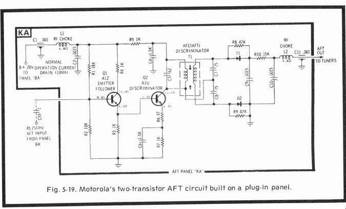
Fig. 5-19. Motorola's two-transistor AFT circuit built on a plug-in panel.
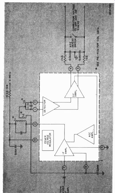
Fig. 5-20. Bloc, Ciagranlot RCA's ZA integrated circuit AFT.
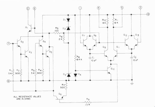
Fig. 5-21. Schematic of The CA3064 AFT IC.
The CA3064 all integrated circuit automatic fine tuning control circuit in a TO-5, 10-lead circular can, is in a separately shielded compartment at the rear of RCA's CTC46, 49 MAK video IF module. It contains (Fig. 5-19) a limiter amplifier, balanced detector, differential amplifier, AGC amplifier and voltage regulator. It is functionally similar to the previous CA 3044, but with input transistors and detectors instead of diodes.
The input (Fig. 5-20) is applied to the Q2 emitter follower stage through pin 6 and thence into Q3, which is in cascode with Q1, the feed (at pin 2) for the L1 primary winding of the discriminator transformer. The output of the transformer's tuned secondary supplies Q7 and Q13 with out-of-phase voltages through pins 1 and 3, respectively. A tertiary winding from L2 is connected to the base of Q1 through terminal 6 and to the bases of Q8 and Q12 that, together with Q7 and Q13, form a peak detector. The Q7 and Q13 emitter outputs pass to Q9 and Q11, which is, with Q10, a constant current driven differential amplifier with the collectors DC coupled to the tuner. Here, either Q9 or Q11 conducts more or less and delivers a corrective voltage that is used by the tuner for frequency correction. For instance, a negative frequency deviation causes Q9 to conduct more and a positive frequency deviation turns on Q11 harder.
AGC action comes from the collector of Q10 through R9 to the base of Q6. This transistor then helps regulate the bias for Q4 and Q7, thus limiting the operation of each transistor.
Narrow band dynamic control is just over the range of plus and minus 30 kHz.
QUESTIONS
1. Draw a response curve showing the relative positions of the video IF and chroma subcarrier markers.
2. What are the two basic traps on any TV IF response curve and what are the frequencies?
3. Name the traps nearest the skirts of any IF response curve and identify as to frequency.
4. Which is at the higher frequency-the sound or video carrier, and by how much?
5. Most UHF tuners are tube-type tuners. True or False?
6. Some TV watchers say there is no real external tuner rejection of unwanted frequencies below 54 MHz. Is this true?
7. Name some favorable tuner characteristics.
8. What is the basic function of any tuner?
9. Cross modulation means what?
10. Do you think semiconductors make better RF amplifiers than tubes?
11. What's the difference between switch-type and turret tuners?
12. How do varactors work?
13. Describe the function of a color video IF strip.
14. Why doesn't the luminance bandpass on color receivers exceed about 3.5 MHz?
15. Write from memory (Table 5-2) the IF traps, carriers and sidebands.
16. Traps determine what characteristic of any swept response curve?
17. Name the three carriers that should appear on all TV response curves.
18. Does the lower adjacent-sound trap also trap out the sound carrier?
19. Why do you think series dropping resistors in vacuum tube receivers are inefficient?
20. Why do you suppose T3 in Fig. 5-15 is double tuned?
21. Who put the first video IF monolithic integrated circuit into a television receiver?
22. After reading the circuit description of TV's first IC video IF, do you think an IC will simplify or further involve TV servicing?
23. Do automatic fine-tuning control circuits differ as to 1) function, 2) circuits to make them operate?
Next: Video Amplifiers & Audio Systems
Also see:
TV Antennas and Transmission lines
Air Time--An Intro to Television Broadcasting
TV and Radio Tube Troubles (1958)