SINCE OSCILLATORS generate their own signals they do not require an external input. This is the most obvious difference between oscillators and the amplifiers you read about in sections 2 and 3. (However, you'll see that some oscillators have to be synchronized with an external signal, so this " rule" is not always true.) There are two types of oscillators: L-C oscillators, in which frequency is determined by an inductance-capacitance network; and R-C oscillators, in which frequency is determined by a resistance-capacitance network.
In both types the active element is a vacuum tube or transistor acting as an automatic switch that chops the DC supply current into a series of pulses. In most R-C oscillators the output will be in the form of pulses of various shapes. In an L-C oscillator the resonant circuit transforms the chopped DC into sine waves, as you will see in the first circuit we discuss: the Hartley oscillator.
L-C OSCILLATORS HARTLEY OSCILLATOR
The Hartley oscillator is one of the most important and widely used oscillator circuits. Figures 4.1 and 4.2 are two examples of this circuit.
Distinguishing Features
The Hartley oscillator employs a vacuum tube or transistor connected in a grounded-cathode or common-emitter circuit.
There is no external AC input. Instead, a resonant circuit consisting of a fixed or variable capacitor in parallel with a tapped inductor is connected across what would be the input in an amplifier. (Compare Figures 4.1 and 4.2 with Figures 2.1 and 2.2 in section 2.) Part of the inductor is connected between the cathode or emitter and " ground " (B-), or between the plate and collector and ground, to provide positive inductive feedback, as in Figures 4.1 and 4.2.
Uses Hartley oscillators are used in a great many different circuits, including radio receivers and transmitters, audio oscillators and other applications where a sine wave signal is required.
Detailed Analysis DC Subcircuits: In Figure 4.1 electron low is from B-, via the lower portion of L1 to the tap, to the cathode of V; and from the plate of V back to B+.
In Figure 4.2 electron low is from B- to the emitter of Q; and from the collector via L2 back to B+.
AC Input Circuits: In Figure 4.1, when power is applied current lows through the lower portion of L1 to the cathode of V, increasing
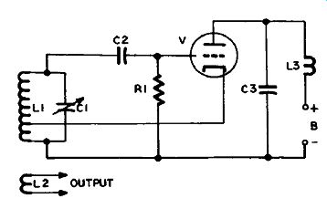
Figure 4.1 Hartley Oscillator (Cathode Feedback)
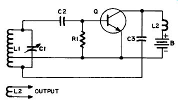
Figure 4.2 Hartley Oscillator (Collector Feedback) as it overcomes the coil's
inductive reactance. The changing lux lines induce a similar build-up of current
in the upper portion of L1, which charges positively the upper side of C1.
This increasing positive voltage is coupled to the grid of V by C2.
A positive bias on the grid of V causes the tube to conduct heavily, resulting in a further increase of current in L1, and even higher voltage on the grid of V.
The positive voltage on the grid would continue to rise indefinitely except that it increasingly attracts electrons in transit from the cathode to the plate, until they build up a negative charge that balances the positive voltage. The current through the tube levels off, and consequently the current through the lower part of L1. No more is induced in the upper part of the coil, because the lux has stopped changing.
C1 now starts to discharge. Its positive charge dissipates faster than the negative charge on the grid, so the tube is gradually cut of, and ceases conducting.
C1 is discharging through L1. The excess of electrons on its lower side lows up through L1 to neutralize the positive charge on the upper side. However, as the nature of a coil is to oppose any change in the current lowing through it, this current goes on lowing even after C1 is completely discharged, until the upper side of C1 becomes negatively charged, reinforcing the negative bias on the grid of V. Eventually the negative charge on the upper side of C1 builds up sufficiently to stop the current flowing through L1, and now the excess of electrons begins to low in the opposite direction. This continues until the negative charge has been returned to the lower side of C1 and a deficiency of electrons makes the upper side positive again.
The restoration of a positive charge to the upper side of C1 is coupled by C2 to the grid of V, and starts the tube conducting again, so that the complete cycle is repeated. This goes on, cycle succeeding cycle, as long as power is applied to the circuit.
The frequency of oscillation depends upon the reactance of L1 and the capacitance of C1, as their combination determines the rate at which the charge of electrons is switched back and forth between the two sides of C1.
In Figure 4.2 the only difference is that the lower portion of L1 is in series with the collector, so that the feedback is from the output side of the transistor, and is therefore of opposite phase to the input. The tap on L1 is therefore connected to the low side of the circuit instead, so as to have the feedback in proper phase to reinforce the oscillations in the grid.
AC Output Subcircuits: The current lowing to and fro in L1 builds up and dies down in such a way that the voltage across it alternates between positive and negative in the smooth curve we call a sine wave.
These sine waves are coupled inductively into the output coil L2.
COLPITTS OSCILLATOR
The Colpitts oscillator is very similar to the Hartley oscillator, except that it uses capacitative feedback instead of inductive feedback. Figures 4.3 and 4.4 are examples of this circuit.
Distinguishing Features
The Colpitts oscillator employs a vacuum tube or transistor connected in a grounded-cathode or common-emitter circuit.
There is no external input. Instead, a resonant circuit consisting of an inductor in parallel with two capacitors in series (or a split-stator variable capacitor, or the equivalent), which is the capacitative opposite number of the Hartley tapped inductor, is connected in a similar way to give positive capacitative feedback.
Uses
Colpitts oscillators are used in a great many different circuits, including radio receivers and transmitters, audio oscillators and other applications where a sine wave signal is required.
Detailed Analysis DC Subcircuits: In Figure 4.3 electron low is from B- via V and L2 to B+. In Figure 4.4 it is from B- via Q, R3 and L2 to B+.
Bias for Q is stabilized by R1 and R2.
AC Subcircuits: In Figure 4.3, when the oscillator is first turned on current lows through L2, causing a voltage drop which charges C3.
The charge on C3 starts oscillation in the resonant circuit consisting of L1, C1, C2 and C3. (As far as resonance is concerned the three capacitors count as one.) The voltage developed across C2 is the feed back voltage, which is applied between the grid and cathode of V. As
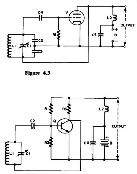
Figure 4.3 Basic Colpitts Oscillator; Figure 4.4 VHF Colpitts Oscillator
this voltage increases positively it causes the resistance of V to decrease, so that it conducts more. This, in turn, increases the current low through L2, and charges C3 more. Eventually the electrons collecting on the grid of V balance the increase in the positive voltage, as you saw in the Hartley oscillator, and C2 starts to discharge through L1.
The amount of feedback depends upon the ratio of the values of C2 and C3. The smaller capacitor will have the higher reactance, and will have the greater voltage drop across it. If this is C2, a higher voltage will be applied between grid and cathode; if C3, a lower voltage.
C1 is a variable capacitor, which allows the resonant circuit to be tuned to the desired frequency. If it is omitted, the resonant circuit will oscillate at a single frequency determined by the combination of L1 and C2 and C3 (which will act as a single capacitor).
In Figure 4.4, the capacitors C2 and C3 of Figure 4.3 have been omitted, but otherwise the circuit is the same. At the higher frequencies used in TV and FM tuners the base-emitter capacitance of Q replaces C2, and the collector-emitter capacitance of Q replaces C3. If you were to sketch in these capacitances you'd have the circuit of Figure 4.3 again, except for a transistor instead of a vacuum tube.
The circuit in Figure 4.4 is also known as the Ultra-Audion oscillator. When it was invented it was not immediately recognized for what it was-a VHF Colpitts oscillator. It doesn't matter which name you use.
ELECTRON-COUPLED OSCILLATOR
Figure 4.5 shows an electron-coupled oscillator.
Distinguishing Features The electron-coupled oscillator employs a pentode or tetrode vacuum tube in a grounded-cathode circuit.
There is no external input. Instead, a Hartley or Colpitts resonant circuit is connected across what would be the input in an amplifier.
The vacuum-tube cathode, control grid and screen grid are connected as if they were the cathode, grid and plate of the triode in Figure 4.1. The output is taken from the pentode plate.
Uses
Triodes provide considerable capacitative coupling between input and output. In some cases this can be a problem, as, for example, when loading the output causes a frequency shift in the resonant circuit in the input. In circuits subject to this, and where it would be a disadvantage, the isolation between input and output provided by a pentode or tetrode vacuum tube in an electron-coupled oscillator is one answer.
Detailed Analysis DC Subcircuit: In Figure 4.5 electron low is from B- via the lower portion of L1 to the cathode of V, and thence from the plate via L2 and the screen grid via R2 back to B+.
AC Subcircuits: The circuit in Figure 4.5 is a Hartley oscillator, identical with that in Figure 4.1, except that the output is taken from the plate of V. The cathode, control grid and screen grid of V act as a triode which is kept cut of most of the time by the negative voltage on the control grid. When the grid goes positive a strong current pulse lows through the tube, causing output signals from both screen grid and plate. The screen-grid signal provides positive feedback via C3 to maintain oscillation, the action of this part of the circuit being exactly as described previously for the Hartley oscillator. In the plate circuit the output signal voltage across L2 is coupled to the next stage.
A resonant circuit similar to that in Figure 4.6 may replace L2.
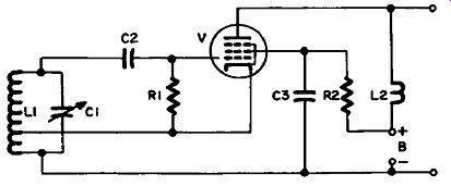
Figure 4.5 Electron-Coupled Oscillator
TUNED-PLATE, TUNED-GRID OSCILLATOR
Figure 4.6 illustrates a tuned-plate, tuned-grid oscillator, so called because there are tuned resonant circuits in both input and output circuits.
Distinguishing Features
A triode or transistor is connected in a grounded-cathode or common-emitter circuit.
There is no external input. Instead, a tuned resonant circuit is connected across what would be the input in an amplifier.
A tuned resonant circuit in the plate or collector circuit provides the means of coupling the signal into the next stage.
Uses
This circuit is not used as much as the Hartley or Colpitts circuits, but you will meet it frequently in the form of a crystal oscillator (described next).
Detailed Analysis
DC Subcircuit: In Figure 4.6, electron low is from B- via V, L2 and L3 back to B+.
AC Subcircuits: When power is turned on electrons flow through the tube and into the side of C3 connected to the plate.
At the same ...
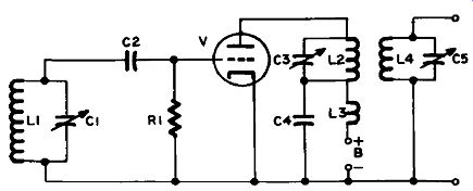
Figure 4.6 Tuned-Plate, Tuned-Grid Oscillator
... time, current begins to low through L2. The resonant circuit C3-L2 begins oscillating, and at the correct moment a positive voltage pulse is fed back to the grid, through the plate-grid capacitance.
The effect of this feedback voltage is to drive the grid in a positive direction, which increases current through the tube and charges C3 still further. However, the positive grid now attracts electrons from the stream of electrons passing from cathode to plate, and they start to low back to the cathode via R1. This resistor has a high resistance, so at this stage electrons build up on the side of C2 connected to the grid faster than they can leak away through R1.
When the positive feedback signal was swinging the grid in a positive direction it was also coupled through C2 to C1, and caused a positive charge to appear on the upper side of this capacitor. But as electrons build up on C2 the grid gradually becomes negative and the tube ceases to conduct. When this happens the feedback voltage disappears and C1 starts to discharge through L1. This causes the resonant circuit C1-L1 to start oscillating at a frequency determined by the inductance of L1 and the capacitance of C1.
Meanwhile C2 completes discharging through R1, and the grid loses its negative voltage, so that V can conduct again. The resonant circuit C3-L2 gets another current pulse to sustain oscillation, and in turn sends one back through V as before, so that the same cycle is repeated continuously as long as power is applied to the circuit.
C3 has to be adjusted so that the frequency of C3-L2 is slightly lower than that of L1-C1 if the feedback voltage is to be in proper phase. The oscillations of the output circuit are coupled into the next stage via L4 and C5, which also form a tuned resonant circuit.
CRYSTAL OSCILLATORS
Figure 4.7 illustrates a crystal oscillator, which is identical to a TPTG oscillator, except that a crystal replaces L1-C1-C2 in Figure 4.6.
Distinguishing Features
A triode or transistor is connected in a grounded-cathode or common-emitter circuit.
There is no external input. Instead, a crystal (X) is connected across what would be the input in an amplifier.
A tuned resonant circuit in the plate or collector circuit provides the means of coupling the signal into the next stage. There is no visible feedback path.
Uses
Crystal oscillators are much more stable than other oscillators; consequently they are preferred where frequency must be controlled to close tolerances. Examples are found in radio transmitters operating on fixed frequencies (such as broadcast stations), precision signal generators, counters and similar applications.
Detailed Analysis
The operation of the circuit in Figure 4.7 is identical with that in Figure 4.6. The crystal (X) replaces the resonant circuit in the grid circuit of the TPTG oscillator.
A quartz crystal will vibrate mechanically at a frequency depending upon its thickness, therefore this frequency is fixed by physical considerations only. In the oscillator the feedback pulses excite mechanical vibrations in the crystal which in turn generate electrical vibrations exactly as if the crystal were a resonant circuit consisting of inductance, capacitance and some resistance. This interaction between mechanical and electrical functions in a crystal is called the piezoelectric effect.
As the dimensions of the crystal are affected by temperature, the frequency is temperature-sensitive. For very accurate frequency control, crystals are installed in crystal ovens, in which they are maintained at a constant temperature by a thermostat.
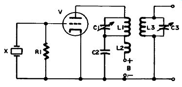
Figure 4.7 Crystal Oscillator
Circuit Variations
A crystal can replace an L-C circuit in other types of oscillator. For example, Figure 4.8 shows how this can be done with a Colpitts oscillator. Compare this circuit with the one shown in Figure 4.3.
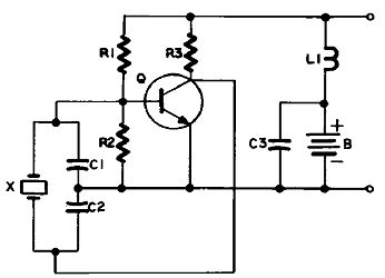
Figure 4.8 Crystal Oscillator (Colpitts Type)
ARMSTRONG, OR TUNED-GRID OSCILLATOR
Figure 4.9 shows an Armstrong oscillator, with the tuned circuit in the grid circuit.
Distinguishing Features
A vacuum tube or transistor is connected in a grounded-cathode or common-emitter circuit.
There is no external input. Instead, a tuned resonant circuit is connected across what would be the input in an amplifier.
A feedback circuit inductively couples the output signal to the grid resonant circuit.
Uses
This circuit is not used as much as the Hartley or Colpitts circuits, but is very similar to the popular blocking oscillator circuit discussed next, to which it makes a good introduction.
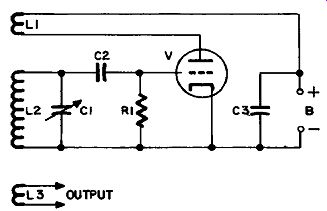
Figure 4.9 Armstrong or Tuned-Grid Oscillator
Detailed Analysis
DC Subcircuit: In Figure 4.9 electron low is from B- via V and L1, back to B+.
AC Subcircuit: The operation of this oscillator is similar to that of the TPTG oscillator, except that feedback is by means of inductive coupling between L1 and L2 instead of via the inter-electrode capacitance of the tube. When power is turned on, the plate current starts to low through L1, building up a magnetic field which induces a voltage in L2. This induced voltage charges C1, and the resonant circuit begins to oscillate in the same way as in the Hartley oscillator discussed at the beginning of the section.
R-C (RELAXATION) OSCILLATORS
Another name for an R-C oscillator is relaxation oscillator. Any oscillator in which the frequency is determined by the rate at which a capacitor can be charged and discharged through a resistance is an R-C or relaxation oscillator.
Multiplying the value of the resistance (in ohms) by the value of the capacitance (in farads) gives the time constant or period, and its reciprocal is the oscillator frequency.
BLOCKING OSCILLATOR
A blocking oscillator is a well-known type of relaxation oscillator.
Figure 4.10 illustrates a blocking oscillator as used in a TV set to generate a sawtooth waveform.
Distinguishing Features
A triode or transistor is connected in a grounded-cathode or common-emitter circuit.
The AC input subcircuit contains a transformer by which feedback from plate circuit to grid circuit is obtained. You might possibly think that this makes it an L-C oscillator, but another look at the transformer will show that there is no parallel capacitor to tune it to resonance, so it is not part of a resonant circuit.
There is usually an external input (a synchronizing signal) which is another indication that this is different from oscillators discussed previously.
Uses
Blocking oscillators are used in many TV circuits to provide the driving signals for vertical (field) and horizontal (line) deflection in the picture tube. These signals take the form of a sawtooth, in which a steady linear rise in voltage is followed by a sharp drop-off.
Detailed Analysis
DC Subcircuit: In Figure 4.10 electron low is from B- via V, the secondary winding of T1, R3 and R4, to B+.
AC Subcircuits: When power is first applied to this circuit an in creasing plate current lows through the upper winding of T1, and because the magnetic field is building up it induces a voltage in the lower winding, with a polarity that couples through C1 to make the tube grid positive. This attracts electrons to the grid, and a negative charge begins to build up on C1 until V is cut of. It doesn’t take long to charge C1 from the grid, because the tube internal resistance is low between the cathode and grid when the latter is positive. However, when the tube cuts of it is as if a switch had opened. The only way for ...
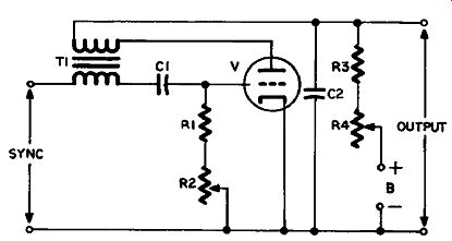
Figure 4.10 Blocking Oscillator (Vacuum Tube)
... C1 to discharge is through R1 and R2. But these resistors have comparatively high values, so it takes C1 considerably longer to discharge than it did to charge. This means that the time during which the tube is conducting is much shorter than the time when it is not. In short, the tube is an automatic switch which is normally "off," but which turns " on " briefly to allow short bursts of current.
So far the circuit has been performing somewhat like the Armstrong oscillator in the previous section. But something different is happening in the plate circuit. While the tube is "turned off, the B voltage starts to charge C2 by pulling electrons away from its upper side. The values of C2, R3 and R4 are chosen so that C2 will not charge to more than about a tenth of the B+ voltage before the tube conducts again. When this happens the burst of electrons supplied by the current pulse through V wipes out the positive charge on C2 (by restoring the missing electrons), and the voltage drops back to its initial value. The result is a sawtooth output voltage, with a slower, steady rise and a faster, sudden fall. Its amplitude is adjusted by R4, which in a TV set would be the height control in a vertical deflection circuit, or the width control in a horizontal deflection circuit.
The frequency of this sawtooth output signal is determined by the time constant of C1, R1 and R2. Since R2 is variable it can be used to vary the frequency of the oscillator. In a TV set this variable resistor is the hold control.
Without a synchronizing signal the oscillator would free-run at its own frequency, which would not be exactly that of the TV signal, so you would get a picture that drifted or rolled. A sync signal is there fore introduced as shown. In a vertical deflection circuit the sync signal will consist of a sequence of positive pulses at the vertical sync rate (60 hertz). On arrival at the grid each positive pulse will cause the tube to turn on, and the circuit will perform one cycle of oscillation and one sawtooth, provided that R2 has been adjusted so that the grid cycle is almost at the point where the tube would have turned on of its own accord.
In a horizontal deflection circuit the sync signal frequency is compared with the oscillator frequency in a frequency comparator circuit (see section 12). The frequency difference becomes a DC voltage.
If the oscillator is too slow the voltage will be positive, if too fast it will be negative. This voltage is applied to the grid of the tube or base of the transistor. A positive voltage will decrease the negative voltage on C1, so that it will discharge faster, speeding up the frequency of oscillation, while a negative voltage will have the opposite effect. As the DC voltage is proportionate to the frequency difference, the frequency will be adjusted automatically to that of the sync signal.
Circuit Variations
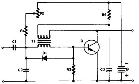
Figure 4.11
Transistor blocking oscillators work on the same principle as vacuum-tube blocking oscillators, with some variations due to the different characteristics of transistors. In Figure 4.11 you see an example of one used in solid-state television sets. The feedback is from collector to base, as in the vacuum-tube circuit you’ve just seen. The free running frequency is determined by C2, R1 and R2 in the same way as C1, R1 and R2 in Figure 4.10. Diode D1 is provided to protect the transistor from damage when it cuts of. When this happens the sudden collapse of the magnetic field in T1 generates a sharp voltage pulse of opposite polarity which is high enough to cause the transistor to break down if not suppressed. The diode is connected with its polarity such that it has no effect on the positive feedback or sync pulses, but short-circuits the reverse spike which we don't want. R4 and C3 are the sawtooth-forming combination, operating in the same way as R4, R3 and C2 in Figure 4.10. The height control in this circuit is located elsewhere. (You will often find it in the following stage instead of where we show it in Figure 4.10.) In some transistor circuits the feedback is from emitter to base instead of from collector to base. Also, a PNP transistor would perform just as well, provided that we reversed the voltage polarity, including that of the sync pulses.
MULTIVIBRATOR
Multivibrators are also R-C or relaxation oscillators. There are two principal types, the plate-coupled (Figure 4.12) and the cathode coupled (Figure 4.13).
Distinguishing Features
Two vacuum tubes (or sections of a dual tube) or transistors, each connected in a grounded-cathode or common-emitter circuit, are inter connected in either of the following ways:
1. Plate-Coupled: The plate of each tube is connected via a capacitor to the grid of the other (in the case of transistors, read collector and base, of course).
2. Cathode-Coupled: The cathodes of each tube are connected to each other, and share a common cathode resistor. The plate of V1A is connected via a capacitor to the grid of V1B, but not vice-versa.
External input of a synchronizing or triggering pulse or DC control voltage is usual, as in the case of blocking oscillators.
Since a multivibrator circuit looks very like a lip-lop, check under flipflop in section 12 if you have any doubt about which it is.
Uses
Multivibrators are used in TV sets in the same way as blocking oscillators. They are also used in many industrial, military and space applications where a pulse output is required. Such uses are legion, but examples would include: timing pulse trains for multiplexing or time-sharing requirements for multi-channel communication and computer-controlled processes; cybernetic controls in guidance systems; sampling systems; and many more.
Detailed Analysis
DC Subcircuits: In Figure 4.12 electron low is from B- through V1A and R1, and V1B and R4, back to B+. In Figure 4.13 electron low is from B- to R3, and thence through V1A and R1, and V1B and R5, back to B+.
AC Subcircuits of Plate-Coupled Multivibrator: The circuit of Figure 4.12 is symmetrical. Each component in one half is duplicated in the other. It is a double switch, in which the tubes turn each other on and off alternately.
Actually, if the circuit were perfectly symmetrical it would be impossible to get it started, but as nothing is ever that perfect one tube will always begin to conduct before the other. For example, suppose V1A is just a fraction faster than V1B. As current begins to low through R1 the voltage on V1A’s plate starts to fall, and a negative going pulse is coupled through C1 to the grid of V1B. This negative bias keeps on increasing as the current through V1A and R1 builds...
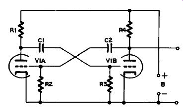
Figure 4.12 Plate-Coupled Multivibrator
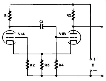
Figure 4.13 Cathode-Coupled Multivibrator
...up, so that by the time V1A is conducting fully V1B is completely cut off.
However, when V1A’s current levels of the negative charge on V1B’s grid begins to leak away through R3 until V1B can conduct.
When this happens its plate voltage falls, because of the potential drop across R4, and the negative-going voltage coupled to V1A's grid now starts to turn it of. This process continues back and fourth as long as power is applied to the circuit.
If we just consider what is happening on C2, we can see that when V1B is turned of no current lows through R4, so the side of C2 connected to V1B's plate charges up to the full B+ voltage. When V1B turns on, the voltage drops by the amount dropped across R4.
Since V1B is switching on and of continuously we get an output from C2 which alternates between these two voltage levels.
The resulting signal is a symmetrical square wave, in a symmetrical multivibrator, but if the R-C combination C1-R3 has a different time constant to C2-R2 the duration of V1A's on and of times will be different from V1B's. This will give an asymmetrical output, in which the upper and lower voltage levels will not have the same duration.
AC Subcircuits of Cathode-Coupled Multivibrator: In Figure 4.13 the two halves of the multivibrator are not symmetrical as far as their components go, since there is only one coupling capacitor, C1. The action of this circuit is more like that of the blocking oscillator, where V1B is the tube and V1A the transformer. Let's see how this is.
Current lowing through V1B causes a voltage drop across R3, which is also V1A's cathode resistor. This voltage drop across R3 biases V1A's grid negatively, so that conduction in V1A decreases and its plate voltage rises. This rising voltage is coupled through C1 to V1B’s grid, increasing conduction in V1B. This, in turn, increases the voltage drop across R3, and the bias on V1A’s grid, so that eventually V1A is cut off altogether.
However, the increasing positive voltage coupled through to the grid of V1B disappears as soon as V1A cuts off, because C1 can only pass a changing voltage, not a DC voltage, and is replaced by a negative bias resulting from conduction through R3. This leads to a down ward swing in the conduction rate through V1B, which reduces the voltage drop across R3, and the bias on V1A's grid. V1A begins to conduct and its plate voltage starts to fall. This negative-going change in its plate voltage is coupled through C1 to V1B’s grid, until the tube is turned off. V1B remains turned off until the negative charge on its grid leaks away through R4. When it gets down to the level where V1B starts to conduct again a new cycle begins.
The output of this circuit is the same as in the plate-coupled multi vibrator, a two-level DC voltage, the levels changing as V1B switches on and off. This DC signal becomes an AC signal by coupling it through a capacitor to the next stage.
Sawtooth Generator
By connecting a capacitor and resistor in series across the output, as was done in Figures 4.10 and 4.11, the output signal would become a sawtooth. The operation of the circuit would be the same as was explained for those circuits.
Sync Input
Sync input is similar to that for blocking oscillators, and works in the same way.
Circuit Variations
Transistors frequently replace tubes in substantially similar circuits, although to date transistor multivibrators are not used in TV sets.
There are also multivibrators in which a triode and a pentode replace the two triodes. Such a circuit would be one in which the second stage had, for reasons of economy, to double as a power output amplifier.
Such a circuit is shown in Figure 4.14. The tubes shown are often half-sections of a dual tube.
At first you might not see much similarity between Figure 4.12 and Figure 4.14, but this is only because we have shown the entire circuit, in which V2 is also a power amplifier driving the vertical deflection coils of the picture tube. The plate of V1 is connected to the grid of V2 through C6, and the plate of V2 is connected back to the grid of V1 through R8, C5, R3 and C2. It is only this feedback loop that complicates the picture.
The output signal from the plate of V2 is far too strong to apply directly to the grid of V1, and must also be filtered to get rid of nearly all the sawtooth, not to mention some strong spikes on it, before it can be used to control V1. The resistors and capacitors through which it passes, together with R4 and C3, form a filter. You can read about filters in section 8, so we'll not take time to go into it here. There are several variations possible in the arrangement of the resistors and capacitors in the filter, but they all serve the same purpose, to transform a portion of V2's output into a form suitable for application to VFs grid.
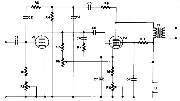
Figure 4.14 Plate-Coupled Multivibrator for TV Vertical Deflection
The sawtooth is formed by the charging and discharging of C4, and its amplitude is controlled by R6 (the height control), so this part of the circuit is the same as C2, R3 and R4 in Figure 4.10. Similarly, R2 is the hold control. The other control, R10, is the linearity control. It varies the DC bias on the grid of V2 in the same way as the control shown in the video amplifier in Figure 2.12. It allows you to shift the operating point of the tube to the proper point on its characteristic curve to give a linear sawtooth output. (See Appendix for explanation of vacuum-tube characteristic curves and class of operation.) T1 is the vertical deflection output transformer, R11 the screen grid voltage-dropping resistor, and C8 the screen-grid bypass capacitor.
SIMPLE RELAXATION OSCILLATOR
Figure 4.15 shows the simplest form of relaxation oscillator.
Distinguishing Features
Capacitor and resistor in series with power source, shunted by a gas-filled tube or lamp.
Uses
A simple relaxation oscillator is not stable or linear enough for TV circuits, but has practical applications elsewhere. In simple oscilloscopes it has been used to generate the sawtooth sweep signal, and it can be used also to make a light lash at a chosen frequency, as in a strobe lamp or the warning lamps used in road repairs.
Detailed Analysis
In Figure 4.15 the battery, B, charges C through R at a rate de pending upon the time constant C X R. The gas in P ionizes when the voltage across C (which is also across P) reaches a certain critical level. P then becomes a low resistance, discharging C rapidly. The lamp then reverts to its original condition of high resistance, and C begins to charge again.
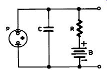
Figure 4.15 Simple Relaxation Oscillator
Circuit Variations
By using a discharge tube instead of a neon lamp a sync signal can be applied to its grid to trigger the tube, thus synchronizing the rate of discharge of C to the external source.
A unijunction oscillator is a similar circuit, where the UJT is a solid-state equivalent of a discharge tube, as shown in Figure 4.16, where C1 and R2 are the sawtooth-forming combination. When the voltage on C1 reaches a level high enough to trigger Q, the resistance between the emitter (arrow) and base 1 (connected to R1) drops, and C1 discharges through Q and R1. The voltage on the emitter now is back where it was, the UJT turns off, and C1 starts to charge again.
A sync signal applied between the emitter and the low side of the circuit will control the rate of firing, as with a discharge tube.
This oscillator can also give a pulse output similar to that of a multivibrator (a rapid switching between two voltage levels) by taking the output from across R1 instead of C1.
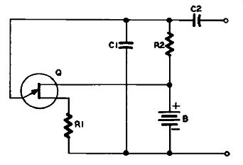
Figure 4.16 UJT Relaxation Oscillator
TROUBLESHOOTING TABLE FOR OSCILLATORS
-------------------