The Nyquist theorem
By definition, an analog signal varies continuously with time. To enable it to be converted into a digital signal, it is necessary that the signal is first sampled, i.e., at certain points in time a sample of the input value must be taken (FIG. 1). The fixed time intervals between each sample are called sampling intervals (ts ).
Although the sampling operation may seem to introduce a rather drastic modification of the input signal (as it ignores all the signal changes that occur between the sampling times), it can be shown that the sampling process in principle removes no information whatsoever, as long as the sampling frequency is at least present in the input signal. This is the famous Nyquist theorem on sampling (also called the Shannon theorem).
The Nyquist theorem can be verified if we consider the frequency spectra of the input and output signals (FIG. 2).

FIG. 1
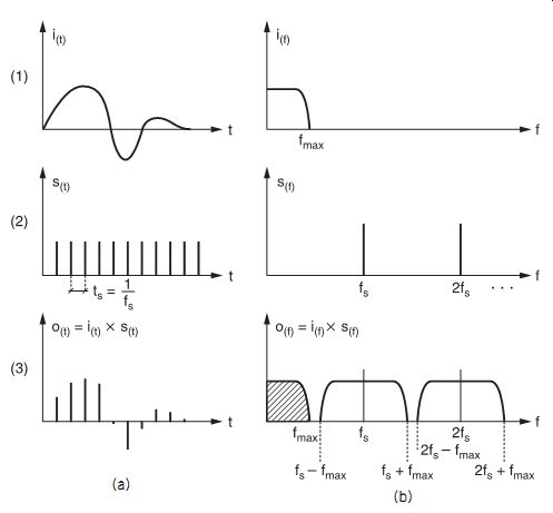
FIG. 2 The sampling process in the time domain (a) and frequency domain
(b)
An analog signal i (t) which has a maximum frequency f max will have a spectrum having any form between 0 Hz and f max (FIG. 2, 1a); the sampling signal s(t) , having a fixed frequency f s , can be represented by one single line at f s (FIG. 2, 2b). The sampling process is equivalent to a multiplication of i (t) and s(t) , and the spectrum of the resultant signal (FIG. 2, 3b) can be seen to contain the same spectrum as the analog signal, together with repetitions of the spectrum modulated around multiples of the sampling frequency. As a consequence, low-pass filtering can completely isolate and thus completely recover the analog signal.
The diagrams in FIG. 3 show two sine waves (bottom traces) and their sampled equivalents (top traces).
Although sampling in FIG. 3b seems much coarser than in FIG. 3a, in both cases restitution of the original signal is perfectly possible.
FIG. 2 (3b) also shows that f s must be greater then 2f max , otherwise the original spectrum would overlap with the modulated part of the spectrum, and consequently be inseparable from it (FIG. 4).
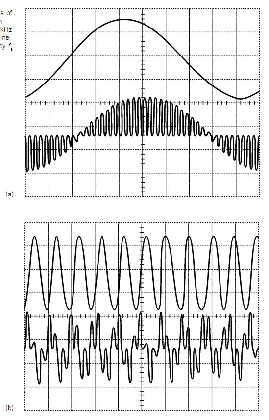
FIG. 3 Two examples of sine waves together with sampled versions: (a)
1 kHz sine wave; (b) 10 kHz sine wave. Sampling frequency fs is 44.056 kHz.
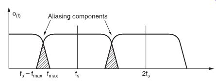
FIG. 4 If sampling frequency is too low, aliasing occurs.
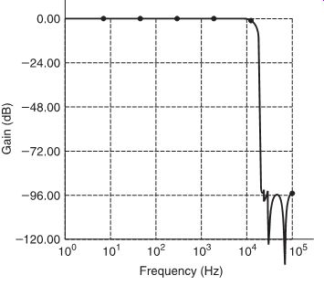
FIG. 5 Characteristics of an anti-aliasing filter.
For example, a 20 kHz signal sampled at 35 kHz produces a 5 kHz difference frequency. This phenomenon is known as aliasing.
To avoid aliasing due to harmonics of the analog signal, a very sharp cut-off filter (known as an anti-aliasing filter) is used in the signal path to remove harmonics before sampling takes place. The characteristics of a typical anti-aliasing filter are shown in FIG. 5.
Sampling frequency
From this, it is easy to understand that the selection of the sampling frequency is very important. On one hand, selecting too high a sampling rate would increase the hardware costs dramatically. On the other hand, since ideal low-pass filters do not exist, a certain safety margin must be incorporated in order to avoid any frequency higher than ½ f s passing through the filter with insufficient attenuation.
EIAJ format
For an audio signal with a typical bandwidth of 20 Hz-20 kHz, the lowest sampling frequency which corresponds to the Nyquist theorem is 40 kHz. At this frequency a very steep and, consequently, very expensive anti-aliasing filter is required. Therefore, a sampling frequency of approximately 44 kHz is typically used, allowing use of an economical 'anti-aliasing filter', flat until 20 kHz but with sufficient attenuation (60 dB) at 22 kHz to make possible aliasing components inaudible.
Furthermore, because the first commercially available digital audio recorders stored the digital signal using a standard helical scan video recorder, there had to be a fixed relationship between sampling frequency (f s ) and horizontal video frequency (f h), so these frequencies could be derived from the same master clock by frequency division.
For the NTSC 525-line television system, a sampling frequency of 44 055944... Hz was selected, whereas for the PAL 625-line system, a frequency of 44 100 Hz was chosen. The difference between these two frequencies is only 0.1%, which is negligible for normal use (the difference translates as a pitch difference at playback, and 0.1% is entirely imperceptible).
Compact disc sampling rate
For compact disc, the same sampling rate as used in the PCM F1 format, i.e., 44.1 kHz, was commonly agreed upon by the establishers of the standard.
Video 8 PCM
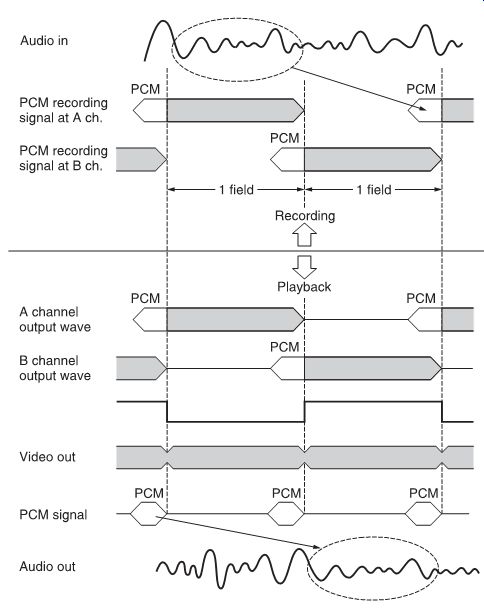
FIG. 6 How PCM coded audio signals are recorded on a section of tape in
a Video 8 track.

Table 1 Horizontal and sampling frequencies of Video 8 recorders, on PAL
and NTSC television standards
The Video 8 recording standard also has a provision for PCM recording. The PCM data are recorded in a time-compressed form, into a 30° tape section of each video channel track (FIG. 6). However, sampling frequency must be reduced to allow the data to fit.
Nevertheless, as the sampling frequency is exactly twice the video horizontal frequency (f h), the audio frequency range is still more than 15 kHz, which is still acceptable for hi-fi recording purposes.
Table 1 lists the horizontal frequencies for PAL and NTSC television standards, giving resultant sampling frequencies.
Also, since only 300 of the tracks are used for the audio recording, a multi-channel (six channels) PCM recording is possible when the whole video recording area is used for PCM.
Sampling rate for professional application
A sampling frequency of 32 kHz has been chosen by the EBU for PCM communications for broadcast and telephone, since an audio frequency range of up to 15 kHz is considered to be adequate for television and FM radio broadcast transmissions.
As we saw in Section 1, stationary-head digital audio recorders are most suited to giving a multi-track recording capability in the studio. One of the aspects of such studio recorders is that the tape speed must be adjustable, in order to allow easy synchronization between several machines and correct tuning.
Considering a speed tuning range of, say 10%, a sampling frequency of 44 kHz could increase to less than 40 kHz, which is too low to comply with the Nyquist theorem. Therefore, such machines should use a higher sampling rate, which at the lowest speed must still be above 2f s.
After a study of all aspects of this matter, 48 kHz has been selected as the recommended sampling frequency for studio recorders. This frequency is compatible with television and motion picture system frame frequencies (50 and 60 Hz), and has an integer relationship (3/2) with the 32 kHz sampling of the PCM network used by broadcast companies. The relationships between sampling frequency and frame frequencies (1/960, 1/800) enable the application of time coding, which is essential for editing and synchronization of the tape recorder. As there is no fixed relationship between 44.1 kHz (CD sampling frequency) and 48 kHz, Sony's studio recorders can use either frequency.
The reason why so much importance was attached to the integer relation of sampling frequencies is conversion: it is then possible to economically dub or convert the signals in the digital mode with out any deterioration. Newly developed sampling rate converters, however, also allow conversion between non-related sampling rates, so that this issue has become less important than it used to be.
Sampling rates for R-DAT and S-DAT formats In the DAT specification, multiple sampling rates are possible to enable different functions:
• 48 kHz, for highest-quality recording and playback.
• 32 kHz, for high-quality recording with longer recording time or for recording on four tracks and for direct (digital) recording of digital broadcasts.
• 44.1 kHz playback-only, for reproduction of commercial albums released on R-DAT or S-DAT cassettes.
Sample-hold circuits
In the practice of analog-to-digital conversion, the sampling operation is performed by sample-hold circuits, that store the sampled analog voltage for a time, during which the voltage can be converted by the A/D converter into a digital code. The principle of a sample-hold circuit is relatively simple and is shown in FIG. 7.
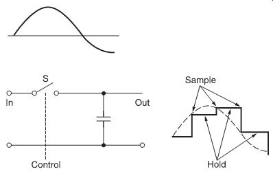
FIG. 7 Basic sample hold circuit.
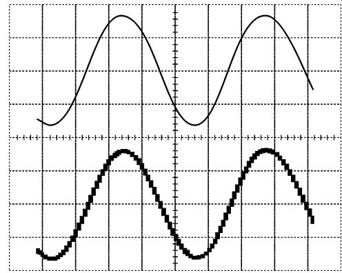
FIG. 8 Sine wave before (top) and after (bottom) sample-hold.
A basic sample-hold circuit is a 'voltage memory' device that stores a given voltage in a high-quality capacitor. To sample the input voltage, switch S closes momentarily: when S re-opens, capacitor C holds the voltage until S closes again to pass the next sample. FIG. 8 is a diagram showing a sine wave at the input (top) and the output (bottom) of a sample-hold circuit.
Practical circuits have buffer amplifiers at input, in order not to load the source, and output, to be able to drive a load such as an A/D converter. The output buffer amplifier must have a very high input impedance, and very low bias current, so that the charge of the hold capacitor does not leak away. Also, the switch must be very fast and have low off-stage leakage. An actual sample-hold circuit may use an analog (JFET switch) and a high quality capacitor, followed by a buffer amplifier (voltage follower), as shown in FIG. 9.
Sample-hold circuits are not only used in A/D conversion but also in D/A conversion, to remove transients (glitches) from the output of the D/A converter. In this case, a sample-hold circuit is often called a deglitcher (FIG. 10).
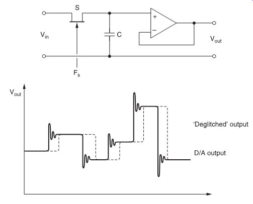
FIG. 9 FET input sample-hold circuit.

FIG. 10 The effect of using a sample-hold circuit as a deglitcher.
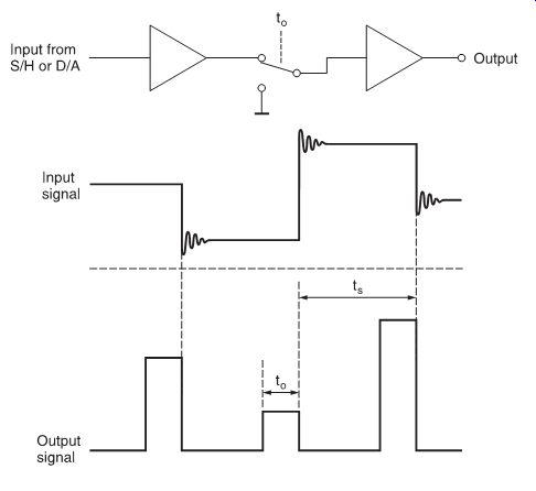
FIG. 11 Basic circuit and waveforms of aperture control circuit.
Aperture control
The output signal of a sampling process is in fact a pulse amplitude modulated (PAM) signal. It can be shown that, for sinusoidal input signals, the frequency characteristic of the sampled output is:
in which fiv = angular velocity of input signal (= 2f v) to
= pulse width of the sampling pulse ts
= sampling period.
At the output of a sample-hold circuit or a D/A converter, however, to
= ts. Consequently:
This means that at maximum admissible input frequency (which is half the sampling frequency), fiv = p/ts , and consequently:
This decreased frequency response can be corrected by an aperture circuit, which decreases to and restores a normal PAM signal (FIG. 11).
In most practical circuits to
= ts/4, which leads to:
At the output of a sample-hold circuit or a D/A converter, however, to
= ts.
Consequently:
This means that at maximum admissible input frequency (which is half the sampling frequency), fiv = p/ts , and consequently:
This decreased frequency response can be corrected by an aperture circuit, which decreases to and restores a normal PAM signal (FIG. 11).
In most practical circuits to

FIG. 11 Basic circuit and waveforms of aperture control circuit.
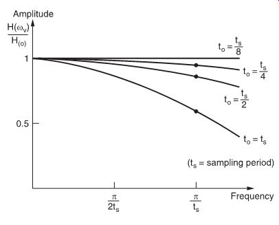
FIG. 12 Output characteristics of an aperture control circuit, as functions
of aperture time and frequency response.
This is an acceptable value: reducing to further would also reduce the average output voltage too much and thus worsen the signal-to-noise ratio. FIG. 12 shows the frequency response for some values of to.
Characteristics and terminology of sample-hold circuits
In a sample-hold circuit, the accuracy of the output voltage depends on the quality of the buffer amplifiers, on the leakage current of the holding capacitor and of the sampling switch.
Unavoidable leakage generally causes the output voltage to decrease slightly during the 'hold' period, in a process known as droop.
In fast applications, acquisition time and settling time are also important. Acquisition time is the time needed after the transition from hold to sample periods for the output voltage to match the input, within a certain error band. Settling time is the time needed after the transition from sample to hold periods to obtain a stable output voltage. Both times obviously define the maxi mum sampling rate of the unit.
Aperture time is the time interval between beginning and end of the transition from sample to hold periods; also, terms like aperture uncertainty and aperture jitter are used to indicate variations in the aperture time and consequently variations of the sample instant itself.