Even after sampling the signal is still in the analog domain: the amplitude of each sample can vary infinitely between analog voltage limits. The decisive step to the digital domain is now taken by quantization (see FIG. 1), i.e., replacing the infinite number of voltages by a finite number of corresponding values.
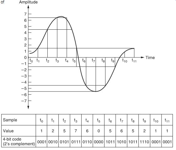
FIG. 1 Principle of quantization.
In a practical system the analog signal range is divided into a number of regions (in our example, 16), and the samples of the signal are assigned a certain value (say, -8 to +7) according to the region in which they fall. The values are denoted by digital (binary) numbers. In FIG. 1, the 16 values are denoted by a 4-bit binary number, as 2^4 = 16.
The example shows a bipolar system in which the input voltage can be either positive or negative (the normal case for audio). In this case, the coding system is often the two's complement code, in which positive numbers are indicated by the natural binary code while negative numbers are indicated by complementing the positive codes (i.e., changing the state of all bits) and adding one. In such a system, the most significant bit (MSB) is used as a sign bit, and is 'zero' for positive values but 'one' for negative values.
The regions into which the signal range is diverted are called quantization intervals, sometimes represented by the letter Q. A series of n bits representing the voltage corresponding to a quantization interval is called a word. In our simple example a word consists of 4 bits. FIG. 2 shows a typical quantization stage characteristic.
In fact, quantization can be regarded as a mechanism in which some information is thrown away, keeping only as much as necessary to retain a required accuracy (or fidelity) in an application.
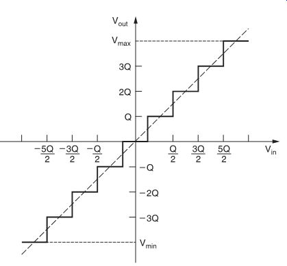
FIG. 2 Quantization stage characteristics.
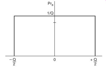
FIG. 3 Probability density function of quantization error.
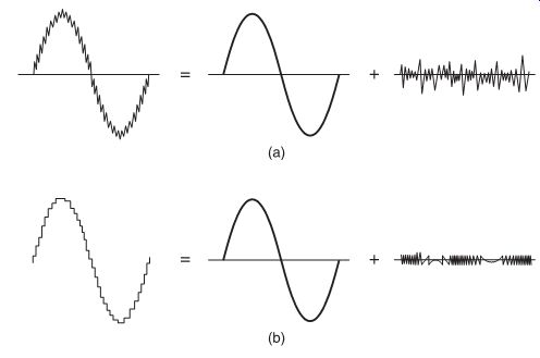
FIG. 4 Analogy between quantization error and noise.
Quantization error
By definition, because all voltages in a certain quantization interval are represented by the voltage at the centre of this interval, the process of quantization is a non-linear process and creates an error, called quantization error (or, sometimes, round-off error).
The maximum quantization error is obviously equal to half the quantization interval Q, except in the case that the input voltage widely exceeds the maximum quantization levels (+ or -Vmax ), when the signal will be rounded to these values. Generally, however, such overflows or underflows are avoided by careful scaling of the input signal.
So, in the general case, we can say that:
-Q/2 < e(n)
< Q/2 where e(n) is the quantization error for a given sample n.
It can be shown that, with most types of input signals, the quantization errors for the several samples will be randomly distributed between these two limits, or in other words, its probability density function is flat (FIG. 3).
There is a very good analogy between quantization error in digital systems and noise in analog systems: one can indeed consider the quantized signal as a perfect signal plus quantization error (just like an analog signal can be considered to be the sum of the signal without noise plus a noise signal; see FIG. 4). In this manner, the quantization error is often called quantization noise, and a 'signal-to-quantization noise' ratio can be calculated.

FIG. 4 Analogy between quantization error and noise.
Calculation of theoretical signal-to-noise ratio
In an n-bit system, the number of quantization intervals N can be expressed as:
N = 2n (eqn. 1)
If the maximum amplitude of the signal is V, the quantization interval Q can be expressed as:
(eqn. 2)
As the quantization noise is equally distributed within ±Q/2, the quantization noise power Na is:
(eqn. 3)
If we consider a sinusoidal input signal with peak-to-peak amplitude V, the signal power is:
(eqn. 4)
Consequently, the power ratio of signal-to-quantization noise is:
(eqn. 5)
Or, by substituting Equation 1:
Expressed in decibels, this gives:
Working this out gives:
S/N (dB) = 6.02 × n + 1.76
A 16-bit system, therefore, gives a theoretical signal-to-noise ratio of 98 dB; a 14-bit system gives 86 dB.
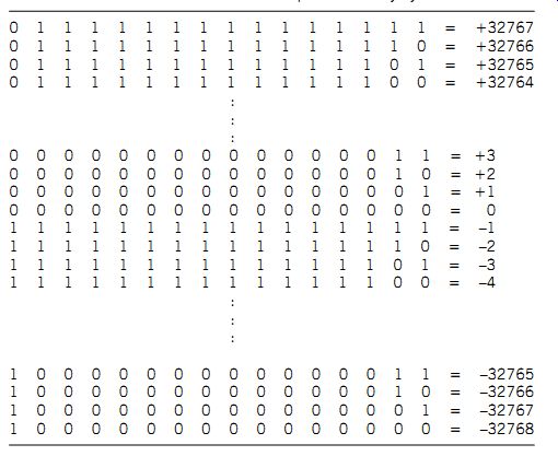
Table 1 Truth table for 16-bit two's complement binary system
In a 16-bit system, the digital signal can take 2^16 (i.e., 65 535) different values, according to the truth table shown in Table 1.
Masking of quantization noise
Although, generally speaking, the quantization error is randomly distributed between + and -Q/2 (see FIG. 1) and is consequently similar to analog white noise, there are some cases in which it may become much more noticeable than the theoretical signal-to-noise figures would indicate.
The reason is mainly that, under certain conditions, quantization can create harmonics in the audio passband which are not directly related to the input signal, and audibility of such distortion components is much higher than in the 'classical' analog cases of distortion. Such distortion is known as granulation noise, and in bad cases it may become audible as beat tones.
Auditory tests have shown that to make granulation noise just as perceptible as 'analog' white noise, the measured signal-to noise ratio should be up to 10-12 dB higher. To reduce this audibility, there are two possibilities:
(a) To increase the number of bits sufficiently (which is very expensive).
(b) To 'mask' the digital noise by a small amount of analog white noise, known as 'dither noise'.
Although such an addition of 'dither noise' actually worsens the overall signal-to-noise ratio by several decibels, the highly audible granulation effect can be very effectively masked by it. The technique of adding 'dither' is well known in the digital signal processing field, particularly in video applications, where it is used to reduce the visibility of the noise in digitized video signals.
Conversion codes
In principle, any digital coding system can be adopted to indicate the different analog levels in A/D or D/A conversion, as long as they are properly defined. Some, however, are better for certain applications than others. Two main groups exist: unipolar codes and bipolar codes. Bipolar codes give information on both the magnitude and the sign of the signal, which makes them preferable for audio applications.
Unipolar codes
Depending upon application, the following codes are popular.
Natural binary code
The MSB has a weight of 0.5 (i.e., 2-1 ), the second bit has a weight of 0.25 (2-2 ), and so on, until the least significant bit (LSB), which has a weight of 2-n. Consequently, the maximum value that can be expressed (when all bits are one) is 1--2-n, i.e., full scale minus one LSB.
BCD code The well-known 4-bit code in which the maximum value is 1001 (decimal 9), after which the code is reset to 0000. A number of such 4-bit codes is combined in case we want, for instance, a direct read-out on a numerical scale such as in digital voltmeters. Because of this maximum of 10 levels, this code is not used for audio purposes.
Gray code
Used when the advantage of changing only 1 bit per transition is important, for instance in position encoders where inaccuracies might otherwise give completely erroneous codes. It is easily convertible to binary. Not used for audio.
Bipolar codes
These codes are similar to the unipolar natural binary code, but one additional bit, the sign bit, is added. Structures of the most popular codes are compared in Table 2.
Sign magnitude
The magnitude of the voltage is expressed by its normal (unipolar) binary code, and a sign bit is simply added to express polarity.
An advantage is that the transition around zero is simple; how ever, it is more difficult to process and there are two codes for zero.
Offset binary
This is a natural binary code, but with zero at minus full scale; this makes it relatively easy to implement and to process.
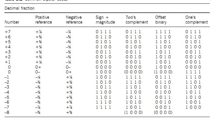
Table 2 Common bipolar codes
Two's complement Very similar to offset binary, but with the sign bit inverted.
Arithmetically, a two's complement code word is formed by complementing the positive value and adding 1 LSB. For example:
+2 = 0010
-2 = 1101
+ 1 = 1110
It is a very easy code to process; for instance, positive and negative numbers added together always give zero (disregarding the extra carry). For example:
0010
+1110
0000
This is the code used almost universally for digital audio; there is, however (as with offset binary), a rather big transition at zero -- all bits change from 1 to 0.
One's complement Here negative values are full complements of positive values.
This code is not commonly used.