Frequency Control System
The frequency control system used to stabilize the center frequency of the master oscillator is more intricate than the rest of the transmitter and just as important, because good center frequency stabilization is one of the prime requisites for direct FM transmitters.
The control system essentially consists of taking some of the master oscillator signal, dividing it, and injecting it, together with another signal, crystal fixed, into a special control circuit. This is similar to the Western Electric and RCA FM transmitters where frequency division is used. However, in the latter transmitters the special control is exercised by mechanical means, (that is, a motor), but in the Federal transmitters a phase discriminator is used as the special control, somewhat similar to an afc circuit. Let us now examine the rest of the block diagram of Fig. 4-28 and then separately study the circuit of the phase discriminator.
Part of the output from the master oscillator buffer amplifier is sent through a series of six divider stages. These divider stages are multivibrator circuits in conjunction with buffer amplifiers. Glancing at Fig. 4-28 we see that the first four divisions are by 2 and the next two divisions are by 4. This means that the frequency of the master oscillator is divided by a factor 2 X 2 X 2 X 2 X 4 X 4 or 256 times.
In other words the master oscillator frequency undergoes a complete division by 256. The relative frequency divisions in conjunction with frequency range of the master oscillator are indicated next to the individual divider stages, the final output frequency being in the range of 14.3 to 17.6 khz. The output, at some one frequency, is injected into one triode section of a 12SN7GT tube acting as a buffer.
A crystal oscillator and divider system is also used where two dividers are employed, one dividing by 2 and the other by 4, so that the final output crystal-controlled frequency can be anywhere in the range of 14.3 to 17.6 khz according to the frequency of the crystal that is chosen. This output frequency, which is of the same frequency range as the master oscillator frequency output from its divider stages, is injected into the other triode section of the duo triode 12SN7GT buffer tube. Due to the complete division of 8 the crystal oscillator chosen must fall within the frequency range of 114.4 to 140.7 khz in order to have the input crystal frequency to the 12SN7GT buffer tube within the range of 14.3 to 17 .3 khz.
As a result of this complete division of 256, the peak deviation change of +3125 cycles of the FM signal from the master oscillator is reduced greatly. It is decreased to the point where the FM master oscillator signal input to the 12H6 discriminator stage (at a frequency somewhere within the range of 14.3 to 17.6 khz) has an equivalent phase deviation so small, that its effect of causing undue phase shift can be neglected.
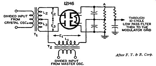
Fig. 4-29. The phase discriminator circuit used in the Federal FM transmitter.
The system of frequency control of the master oscillator is based upon the action of a phase discriminator circuit. To understand this phase discriminator more thoroughly, let us examine a schematic dia gram of this circuit as used in the Federal transmitters. This diagram is shown in Fig, 4-29. A duo-diode 12H6 type is used as the phase discriminator. The important feature of this type of phase discriminator is foe untuned input transformer, which decreases the chance that the discriminator circuit characteristics will change with input frequency. The circuit arrangement provides equal but 180° out-of phase voltages across each half of the center-tapped secondary of T1. These voltages are designated as E2 across half L2 and E3 across half L3. This 180° phase relationship is further indicated in the vector diagrams of Fig. 4-30 where voltage vectors E~ and E3 are seen to be 180° out-of-phase with each other. These voltages will be at the out put frequency of the frequency dividing systems - namely, some where within the range of 14.3 to 17.6 khz. Since the input to T1 is crystal controlled, its frequency is considered to be stable, and consequently the frequency of voltages E/1 and E3 never changes appreciably after a preselected crystal frequency has been chosen.
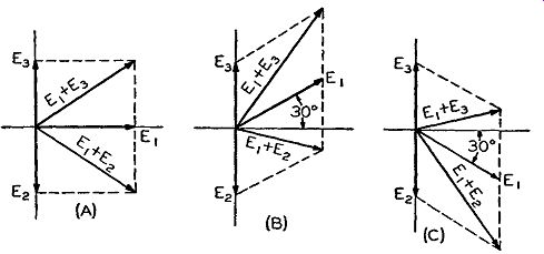
Fig. 4-30. Vector diagrams of the circuit of Fig. 4-29. If the frequency
of the input to T1 is the same as that into T2, then E1 will be 90°
out of phase with E2 and E3 , as shown in (A). If the input to T2 changes,
then the relationship of E1 to E2 and Es changes in phase, as shown in
(B) and (C).
Into the primary of transformer T/I is injected the divided input from the master oscillator, and by transformer action a voltage E1 appears across the secondary L1. If the frequency of the input to T/1 is the same as that into T1, voltage E1 will be exactly 90° out of phase with both voltages E2 and E3. This is shown in the vector diagram of Fig. 4-30 (A). The two diodes of the 12H6 tube receive the same applied voltages under these circumstances, and since they are differentially connected, no output will appear across their load resistors between point A and ground in Fig. 4-29. In other words voltage E1 is common to both diodes, and thus the upper diode receives the series voltages of E1 and E2 and the lower diode receives the series voltages of E1 and E3. The vector additions of these voltages are illustrated in Fig. 4-30 (A), and these resultant voltages show that both diodes receive the same voltage. Hence the individual drops across their respective load resistors, being equal but of opposite polarity, cancel each other.
If the master oscillator drifts in frequency above or below its operating point, the input frequency to transformer T2 will likewise shift, and the input frequency to T2 and T1 will be different since the crystal frequency remains fixed. The phase discriminator then functions to correct this master oscillator instability. With frequency input to T2 changing, the relative phase relationship between voltages E1 and E2 and between voltages E1 and E2 also changes. The phase relation ship change between these voltages makes the voltages applied to the two diodes different. This is indicated in the vector diagrams of Fig. 4-30 (B) and (C). In Fig. 4-30 (B) the voltage E1 is assumed, for discussion purposes, to have a change in frequency that is equivalent to positive phase displacement of 30° from its original position, and in Fig. 4-30 (C} the same amount of frequency change is assumed but in the opposite direction. Therefore, the vector diagrams are illustrative of instances where the master oscillator frequency drifts above or below its true operating frequency. In Fig. 4-30 (B) with a positive phase increase, resultant voltage vector E1 + E8 which exists across the lower diode section of the 12H6 tube is seen to be greater in magnitude than voltage E1 + E2 across the other diode. Hence greater current will flow in the lower diode section and point A of Fig. 4-29 will be negative with respect to ground. In Fig. 4-30 (C) with a negative phase displacement, the situation is reversed, with the upper diode's voltage E1 + E2 greater than the lower diode voltage E1 + E3, and hence a greater current flows in the upper diode.
This makes the voltage drop between point A and ground of Fig. 4-29 such that point A is positive with respect to ground.
Thus we have the phenomenon of a variable polarity existing at point A, and the value of the voltage at this point is determined by how much the master oscillator shifts or drifts in frequency. If this voltage at point A is injected into the modulator grid together with the audio (as it really is}, this voltage at point A will change the gm of the modulator tube and hence the value of the input grid capacitance, so that it will correct the oscillator frequency back to its operating value, and thus stability will be maintained.
THE RAYTHEON INDIRECT FM TRANSMITTER
The Raytheon FM transmitter of today operates on the basis of obtaining a p-m wave but, through the use of the audio correction network, this p.m. is made equivalent to FM Thus the over-all method is called indirect FM As will be recalled, this is the principle used in other indirect FM transmitters, such as Major Armstrong's.
The process of modulation used in these transmitters is different from anything yet discussed. In the two indirect FM transmitters de scribed so far, the p-m signal was obtained in one by an initial process of AM, followed by shifting the double sideband of this signal by 90°, and recombining this double sideband with the initial carrier to obtain the p-m signal (or indirect FM signal). Use of a special tube, the Phasitron, accomplished the same result in the other transmitter.
In the Raytheon transmitters, the initial process is one of p.m., similar to the method discussed in the section on phase modulators in Section 3. The amount of peak phase deviation, and hence equivalent frequency deviation, is quite small for this type circuit, so that quite a number of multiplication stages are needed. To overcome the need for a frequency conversion system. six similar phase modulators are used in cascade. In this way six times the initial phase deviation of a single modulator is obtained fur the same audio input to each phase modulator. The master oscillator frequency is crystal controlled, as is natural for most indirect FM transmitters and, hence, center frequency stabilization is not needed. Let us first analyze the transmitter from an over-all block diagram view of it, and afterward we will study the schematic arrangement of the phase modulator.
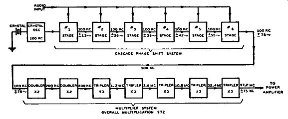
Fig. 4-31. Block diagram of the Raytheon indirect FM transmitter, omit
ting the power amplifier stages.
In Fig. 4-31 a block diagram of the Raytheon indirect FM transmitter is illustrated. It essentially consists of two sections: the oscillator-cascade phase modulator part and the multiplier part. The out put of the multipliers is fed to the power amplifier section of the transmitter. The frequency multiplier stages comprise two doublers and five triplers, so the over-all amount of multiplication is equal to 972 times (2 X 2 X 3 X 3 X 3 X 3 X 3, which equals a multiplication of 4 for the doublers and a multiplication of 243 for the triplers and 4 X 243 equals 972). Since the FM band is 88 to 108 mhz, the value of the crystal oscillator can be anywhere between the range of 88 mhz/972 or 90.65 khz and 108 mhz/972 or 111.11 khz. In brief, the crystal oscillator will be somewhere in the range of 100 khz. Under the assumption that the crystal is exactly 100 khz, the center frequency component of the transmitting signal is consequently 100 khz X 972 or 97.2 mhz. The respective values of the center frequency, before each individual multiplication stage, are indicated in the block diagram of Fig. 4-31 for a 100- khz crystal. To obtain a final output peak frequency deviation of 75 khz, for 100 percent modulation at the lowest audio frequency, the amount of peak frequency deviation of the signal before it enters the frequency multiplication stages (that is, the deviation output from the last of the cascade phase modulators) should be equal to 75 khz/972 or approximately 78 cycles. The amount of peak phase deviation from one phase modulator is about 25°. If this phase deviation is multiplied by the lowest audio frequency of 30 cycles and then divided by the number of degrees in one radian (57.3), the equivalent peak frequency deviation will be obtained. Thus (25 X 30)/57.3 is found to be equal to about 13 cycles. This is the peak frequency deviation output from one phase modulator and, in order to obtain a peak frequency deviation input of 78 cycles to the multiplier system, 13 cycles must be multiplied by 6.
It would be quite easy just to inject the frequency output of 100 khz +13 cycles into a doubler and tripler multiplier and obtain a peak deviation of 78 cycles, if the 100- khz carrier signal were not also multiplied 6 times. The latter is definitely undesirable because a frequency conversion system then would be required to give a final output signal correct in center frequency as well as deviation. Under these circumstances, six separate phase modulators are used and connected in cascade so that each phase modulator produces a phase shift equal to a peak frequency deviation of 13 cycles. The cascaded arrangement of phase modulators has the effect of adding the individual frequency deviations together, giving a total peak frequency deviation of 78 cycles at the output of the complete modulator system, while the center frequency component remains the same as the frequency of the crystal oscillator, namely 100 khz for the case illustrated in Fig. 4-31.
Each modulator stage is so arranged that the same audio voltage is injected into each stage, that is, the audio voltages controlling the amount of phase shift are connected in parallel. The r-f voltage inputs to these modulators are the ones that are connected in cascade.
The Constant Impedance Phase Shift Modulator
One very important feature of a phase modulator is that the output signal must be shifted in phase but not in amplitude. This is a fundamental rule for correct p.m., as stated before in this text. For the output signal from the modulator to remain constant in amplitude, the impedance in the output circuit should remain constant in amplitude for all audio modulating voltages injected. To satisfy this requirement a constant impedance network is inserted in the output of the phase shift modulators. Before examining the actual circuit of a single phase shift modulator and discovering how the audio signal shifts the phase of the r.f., let us examine a simplified circuit of the constant impedance network used in this system.
In Fig. 4-32 is shown a simplified schematic diagram of this constant impedance network as used in the Raytheon indirect FM transmitter. In this circuit the variable resistance R determines the phase shift of the network, and, if R is made variable according to an audio voltage, the phase shift occurring will be in conformity with the varying amplitude of the audio signal. The phase shift that R imposes upon the circuit can be anywhere between +90°. Let us consider the two extremes of operation of the variable resistance R, namly, when its resistance is zero and when it is infinite.
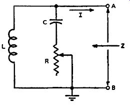
Fig. 4-32, right. Simplified schematic of a constant-impedance network
as used in the Raytheon indirect FM transmitter.
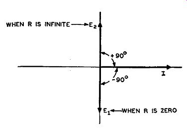
Fig. 4-33, left. Vector representation of the relationships existing
in the constant-impedance network of Fig. 4-32 when R is zero and when
R is infinite.
From Fig. 4-32 it will be noticed that when R has zero resistance, it is as if R were short-circuited, and the low end of capacitor C is effectively grounded. Under these circumstances the current that flows in the circuit is purely reactive ( considering only a pure inductance and capacitance). If the value of the inductive reactance is made greater than the capacitive reactance (twice as great in this problem) at the crystal oscillator frequency, the parallel circuit is predominantly capacitive, and the total effective current I flowing through the circuit will be leading the voltage across it by 90°. This is shown in the vector diagram of Fig. 4-33, where current vector I is seen to be leading voltage vector E1 by 90 °. If, at the other extreme, the value of R increases to an infinite value, it is as if the resistance were open-circuited. In this case the capacitor has no effect, because one end is considered to be open.
Consequently, the circuit is strictly inductive, and the current I lags the voltage across the circuit by 90°. This is also indicated in the vector diagram of Fig. 4-33 where voltage vector E2 represents the voltage across the circuit when R is effectively infinite. With varying values of R the phase shift will be somewhere between ±90°. Now let us return to the topic of the constant impedance of the network of Fig. 4-32.
If the inductive reactance is made equal to twice the capacitive reactance, the magnitude of the impedance Z seen looking into terminals A, B of Fig. 4-32 will be constant for all values of R. This statement can be proved mathematically, but its proof is beyond the scope of this text, as it involves higher mathematics. The magnitude of the impedance will be constant and equal to the inductive reactance ( or twice the capacitive reactance.) Replacing the variable resistance R in this network by the dynamic plate resistance of a tube, and having this resistance varied by an input audio signal will phase modulate an r-f voltage impressed across the network by an r-f amplifier. This was simply explained in Section 3 with reference to Figs. 3-11, 3-12, and 3-13. However, the plate resistance of the r-f tube (that injecting the r-f signal across the circuit) and the series resistance of the coil has a slight effect on the phase shift of the circuit. However, the values of these two resistances have a negligible effect on the magnitude of the constant impedance network.
It has been found that, when the variable resistance R is replaced with the dynamic plate resistance of a tube, it is not possible to obtain the necessary frequency deviation for 100 percent modulation at the lowest audio frequencies, because the voltage on the grid of this tube at these low frequencies is very critical and distortion may result.
To make sure that the audio modulation does give the maximum amount of frequency deviation, a vacuum tube is used as the source of variable R, but the dynamic plate resistance does not take the place of R. To understand what is done, an actual circuit for a single stage phase modulator is shown in Fig. 4-34.
The 6SJ7 tube serves as the r-f amplifier and impresses an r-f voltage across the constant impedance network consisting of coil L in parallel with the series combination of capacitor C and one section of a duo-triode 6SN7GT tube called the resistance tube. The constant impedance part of this circuit is the same as that in Fig. 4-32, with one section of the 6SN7GT tube serving the purpose of the variable resistance R in Fig. 4-32. The resistance between the cathode and ground of the 6SN7GT tube varies in accordance with the audio impressed on the grid of the same tube, thereby shifting the phase of the r-f voltage appearing across the inductance L. The 6SN7GT cathode resistor RK is not bypassed so that the audio signal currents flow through RK. The value of RK and the applied r-f voltage across the constant impedance network are so chosen that there is a constantly changing value of resistance across the cathode to ground circuit of the 6SN7GT resistance tube. Hence, the correct value of phase shift is obtained for the proper output deviation. The value of the resistance appearing between the cathode to ground of the 6SN7GT tube is somewhat similar to that of an ordinary cathode follower.
The complete cascaded phase shift modulator employs nine tubes.
Six of these are 6SJ7's and serve the purpose of r-f amplifiers. The other three tubes are 6SN7GT duo-triode amplifiers which are employed as the resistance tubes with one section being used to supply the varying resistance for each phase modulator stage. All the grids of the 6SN7GT tubes are connected in parallel and therefore receive the same audio modulating signal input. If all the single modulator stages are exactly the same in component parts and applied voltages, there will be a perfectly operative six fold phase shift modulator system with any appreciable AM prevented by the constant impedance network.
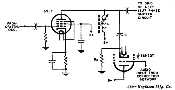
Fig. 4-34. A single-stage phase modulator, where the 6SJ7 is the r-f
amplifier and the constant-impedance network is L in parallel with the
series combination of C and one section of the 6SN7GT, the resistance
tube.
THE WESTINGHOUSE DIRECT FM
In its FM transmitter, the Westinghouse Electric Corporation employs a system of direct FM different from any of the previous systems. Since the method is one of direct FM, a variable frequency oscillator (vfo) is used, and consequently a system of frequency stabilization is employed. The frequency stabilization is of a completely new style compared with anything already studied. The most important parts of this transmitter are these two units -- namely, the modulator and frequency stabilization systems.
The frequency multiplication system does not use as many stages as is usual with indirect FM transmitters. Two tripler stages are used to give an over-all frequency multiplication of 9. The oscillator itself is used as one of the triplers, and the other tripler uses the dual tetrode beam power tube type 829B in a push-pull arrangement. Since the multiplication is nine-fold, the initial amount of peak frequency deviation at the oscillator-modulator stage, for a 75-khz peak deviation output, is equal to 75/9 or 8.333 khz. Likewise the variable frequency oscillator has to be somewhere in the range of 88/9 or 9.778 mhz to 108/9 or 12.0 mhz, so that the final output frequency will fall within the complete FM band of 88 to 108 mhz.
The Oscillator-Modulator System
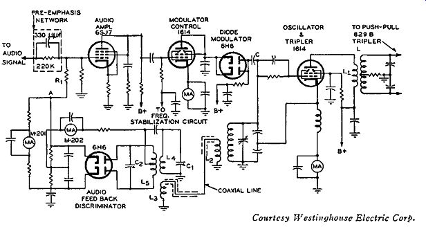
Fig. 4-35. Oscillator-modulator system of the Westinghouse direct FM
transmitter.
Fig. 4-35 illustrates the oscillator-modulator system of these transmitters. The circuit uses a beam power tetrode type 1614 tube as a Colpitts electron-coupled oscillator. Since this 1614 tube also operates as a tripler, the grid circuit is tuned to 1/9 of the output frequency of the transmitter, and the plate circuit is tuned to 1/3 of the output frequency. L, is the plate inductance of the oscillator tripler tube, and at a first glance it may be difficult to see how plate tuning is accomplished. This coil in conjunction with coil L forms an r-f transformer in which both coils are wound on the same coil form. As these coils are very closely coupled (a high coefficient of coupling exists), the mutual inductance is quite high, and consequently the plate circuit of the oscillator is effectively tuned simultaneously with the secondary tuned circuit.
A standard pre-emphasis type network in conjunction with a 6SJ7 class A audio amplifier is used in the audio section. The output from this amplifier is fed into the modulator control tube type 1614. This varying audio varies the plate current of the tube at an audio rate, and, in turn. the plate current affects the 6H6 diode modulator tube which injects a varying reactive effect across the oscillator tank circuit. This reactive effect is varying at an audio rate and consequently varies the oscillator tuned grid circuit at the same audio rate, thus frequency modulating the carrier frequency of the oscillator.
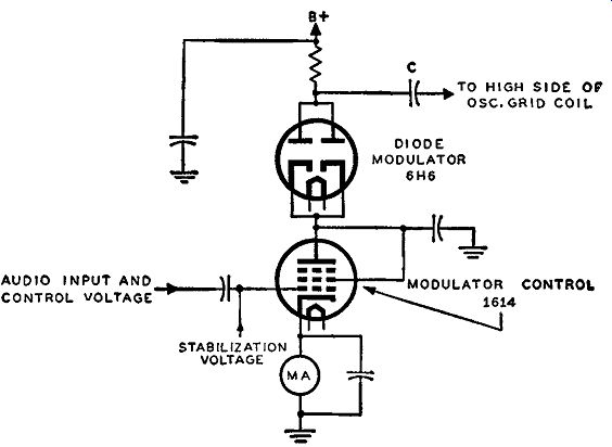
Fig. 4-36. Simplified schematic of the modulator circuit of Fig. 4-35.
The plate voltage to the 1614 tube is supplied indirectly through the
effective resistance of the 6H6 modulator tube.
Let us analyze this modulator circuit a little more thoroughly in order to understand how FM of the oscillator results. In Fig. 4-36 the modulator circuit, comprising the 1614 modulator control tube and 6H6 diode modulator of the previous circuit, is redrawn for ease of discussion. From this figure (and from that of Fig. 4-35) it will be noticed that the 1614 modulator control tube does not have any B+ voltage supplied directly to its plate. The word directly is used intentionally, because, although at first not apparent, supply voltage does exist on the plate of the control tube but in an indirect manner. The plate voltage is supplied to the tube through the effective resistance of the 6H6 diode modulator tube.
It is readily seen that B+ voltage exists on the plates of the 6H6 modulator tube (the plates, as well as the cathodes, are connected in parallel) and that the only path available to complete the d-c path to ground is through the cathode circuit of the 1614 control tube to ground. This means that the voltage that exists between the plates of the diode and ground is divided into two parts. One part exists between the plates and cathodes of the 6H6 tube, and the other part is between plate and ground of the 1614 tube (the voltage drop across the milliammeter is negligible). For example, let us assume that 275 volts exists on the plates of the diode tube and that the resistive effect of this tube is such that a potential drop of 5 volts exists across it.
Thus the cathodes of the 6H6 tube are 5 volts less positive than the plates and consequently the voltage on the cathodes is equal to 270 volts. Since the 6H6 cathodes and plate of the 1614 tube are directly connected, 270 volts are also said to exist on the plate of this 1614 control tube and these 270 volts can be measured between this plate and ground.
With the understanding of how an effective supply voltage does exist on this 1614 tube, it is readily conceivable that the current flowing through the control tube also has to flow through the 6H6 modulator tube. The instantaneous current flowing through the diode, therefore, depends upon the current flowing through the 1614 control tube. Before we discuss the action of the diode modulator tube in detail, let us delve a little deeper into the .functioning of the control tube.
This type 1614 control tube has the screen tied to its plate so that it functions as a triode. The voltages applied to the tube are such that the tube operates as a class A audio frequency amplifier. Applied to the grid of this tube are two signals, one a variable audio signal (the intelligence to be transmitted) and the other the control voltage from the frequency stabilization system. Since this control tube is operated as a class A amplifier the current flowing through it ( due to the audio and stabilization signals) and hence through the 6H6 modulator tube is always proportional to the instantaneous value of grid voltage. The modulator tube in conjunction with capacitor C presents a net reactive effect to the oscillator grid circuit, and, consequently, the audio signal must vary this reactance to frequency modulate the oscillator.
The automatic frequency control voltage from the frequency stabilization unit determines the static operating conditions of the control tube and thus establishes the static reactance characteristics of the modulator. In other words, without any audio applied to the control tube only the stabilization voltage exists on the tube, and a fixed or static reactive effect, due to this voltage, is presented by the diode modulator to the oscillator grid tank circuit. The value of this reactive effect causes the oscillator to provide the proper frequency when no modulation (that is, no audio signal) is present. It also establishes the point from which the reactance will vary above and below this fixed or static value and thus frequency modulate the oscillator above and below the established frequency when no modulation is present. With the operation of the 1614 as modulator control tube known, let us now analyze how the 6H6 modulator tube functions in conjunction with the control tube.
The diode modulator tube in conjunction with the circuit capacitances presents an impedance to the circuit; that is, it contributes both a resistive effect and a reactive effect. This is understood from the facts that a d-c voltage drop exists across the diode which contributes to the resistive part and that an interelectrode capacitance exists be tween the plates and cathodes that contribute, in conjunction with other capacitances in the circuit, to the reactive part of the impedance. The instantaneous values of current flowing through the diode consequently have both a resistive component and a reactive component. When the value of the instantaneous current flowing through the tube is changed by the audio modulating signal on the control tube, the resistive and reactive parts of this current change accordingly. Since the reactance of the circuit is on the capacitive side, the instantaneous current flowing through the diode is always leading the r-f voltage existing across the circuit. The vector diagram and simplified schematic of Fig. 4-37 will make this somewhat clearer.
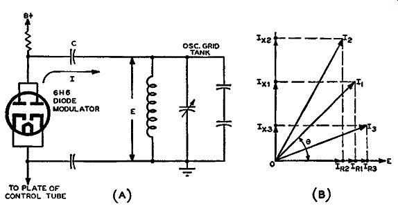
Fig. 4-37. The simplified schematic of the 6H6 diode modulator of the
Westinghouse FM transmitter (A) and the vector representation (B) of
the instantaneous currents flowing in the circuit (A). This shows that
the resistive current change is small compared with the reactive current
change.
With no modulating signal applied to the control tube, the current I flowing through the circuit leads the voltage E across the circuit by some phase angle. This current is designated as 11, and in the vector diagram of Fig. 4-37 (B) it is seen to lead the voltage E by some phase angle called(). By dropping perpendiculars from the terminal point of I_1 to its respective vertical and horizontal axes, the reactive and resistive parts of the current can be seen. Thus the resistive current becomes IR1 and the reactive current Ix1. At once it is apparent that the resistive current IR1 and voltage E are in phase with each other and that the reactive current I_x1 is in quadrature (leading by 90°) with the voltage E. These resistive and reactive components of current produce across the oscillator tuned circuit a fixed resistance and a fixed capacitance which are determined by the effective values of IR1 and Ix1 , If this reactive current can be made to vary in accordance with the audio signal, the effective capacitance that is injected across the oscillator grid tank circuit also will vary and, consequently, FM of the oscillator signal will be obtained.
When an audio modulating signal is applied to the grid of the modulator control tube, the value of the current flowing through this control tube, and hence through the 6H6 diode modulator, will change at each instant. Thus current I flowing in the circuit of Fig. 4-37 will be a varying current, changing in accordance with the applied audio and, therefore, is considered as an instantaneous current. On the positive half cycle of audio, the grid of the control tube becomes less negative, and the instantaneous current flowing through the circuit increases in magnitude and also changes in phase with respect to the voltage E existing across the circuit. This current is designated as I11 on the vector diagram. Dropping perpendiculars from this current makes the resistive and reactive parts clearly evident, the new reactive current being Ix11 and the resistive current I Rs. On the negative half cycle of audio, the grid of the control tube becomes more negative, and the instantaneous current flowing through the circuit decreases in magnitude and also changes in phase with respect to the voltage E existing across the oscillator grid tank circuit. This current at a certain instant on the negative half cycle of audio is designated as Is on the vector diagram of Fig. 4-37 (B). The resistive and reactive components of current are readily determined and designated IRs and Ix.~, respectively. Examination of the over-all vector diagram reveals that, when the audio signal increases the instantaneous current, the reactive current increases and the resistive current decreases, and, when the instantaneous current decreases, the reactive current decreases and resistive current increases. Also, the total change of the reactive current is very much greater than that of the resistive current.
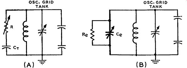
Fig. 4-38. Simplified schematic (A) of the oscillator-modulator circuit
of Fig. 4-37 (A) and the equivalent circuit is shown in (B).
To understand how the oscillator is frequency modulated let us examine the simplified circuits of Fig. 4-38. In part (A) resistor R represents the variable resistance of the diode and capacitor Cp rep resents the total capacitances in the circuit that are effectively in series with the diode resistance. This series RC,,. arrangement is in parallel with the oscillator grid tank. The instantaneous current flowing through this network (I in Fig. 4-37) contains both a resistive and reactive component. Due to the varying audio modulating signal, the resistance of the diode changes, producing a change in the instantaneous current I; therefore, the resistive and reactive parts of the current also change. Looking back from the oscillator tank toward the diode modulator circuit, a parallel resistive and capacitive component can be seen due to the resistive and reactive parts of the current I. These components are shown in Fig. 4-38 (B) where Re is the equivalent parallel resistance and Ce the equivalent parallel capacitance.
Only Ce is illustrated as a variable and not Re because the vector diagram of Fig. 4-37 (B) showed that the resistive current change is negligible compared to the capacitive current change. Circuit (B) of Fig. 4-38 is equivalent to circuit (A) despite the interchange of the variability from R of circuit (A) to Ce of circuit (B). This can be proven mathematically but it is beyond the scope of this guide.
Consequently, when an audio signal is applied to the modulator control tube, there is injected a variable reactance across the oscillator grid tank circuit in accordance with this audio, so that the oscillator signal is frequency modulated. The resistive change, as mentioned, is so small compared with the reactive change that effective resistance change injected along with the reactive change across the oscillator tuned circuit is considered negligible. That is, the voltage drop across the diode modulator tube changes very little during the varying cur rent flow through the tube, which means that a-m effects due to such voltage changes are negligible.
The 6H6 diode was chosen as the modulator because it provides greater freedom from noise than does a conventional reactance tube modulator. Another main reason for its use is the greater ease in establishing its operating range (the range over which it operates in conjunction with the modulation signal) so that AM of the oscillator, due to resistive changes is practically eliminated. One of the primary problems of design in any type of reactance modulator is to minimize as much as possible any changes in the resistive voltage drop across the modulator tube. This voltage drop indirectly appears across the oscillator tank, and if there is a variation or change in this voltage, the change will also appear across the oscillator tank. The effect of this is to cause AM of the oscillator output which is definitely undesired.
As was pointed out, this a-m effect is avoided to a degree where it is considered negligible by operating the diode modulator at a point where the change in resistive current through the tube is very small in proportion to the change in reactive current.
Meter indication is used to make sure that the modulator will be operated within the range producing the minimum amount of resistive current variation over the audio range required for the maximum amount of modulation. The meter in question appears in the cathode circuit of the 1614 control tube as seen in Figs. 4-35 and 4-36. The current registered by this meter flows through both the control tube and the modulator tube. A static current reading of 6 ma establishes the correct operating point of the diode modulator and will, thus, permit variations in either direction sufficient to produce the necessary frequency deviation for the final output FM signal.
Audio Feedback Discriminator Network
Another interesting part of the circuit of Fig. 4-35 is the audio feed back discriminator network. From the schematic diagram it can be seen that this network provides an audio feedback circuit from the 6H6 diode modulator to the 6SJ7 audio amplifier. Briefly, this circuit provides an inverse feedback voltage to the grid of the 6SJ7 audio amplifier to improve the linearity of the audio circuits and the frequency response of the transmitter. The circuit involved is a conventional discriminator detector arrangement such as those commonly used in many FM receivers and in electronic afc systems similar to those discussed in Section 3.
Input voltage to the system is derived by taking a small amount of signal from the oscillator grid inductance by transformer action and coupling this signal through a coaxial line to the audio feedback discriminator network. The complete coupling line consists of inductances L 2 and L 3 and the coaxial line. The primary and secondary inductances L4 and L5 are tuned by capacitors C1 and C2 respectively.
These two capacitors are screw driver adjustments on the front panel of this transmitter and are used to align the discriminator. To simplify the tuning procedure two milli-ammeters, M-201 the "discriminator current differential" meter and M-202 the "discriminator current total" meter, are provided. When the primary tank circuit of the discriminator is tuned in resonance with that of the oscillator, maxi mum current will flow through M-202. When the secondary is like wise tuned to resonance, the current through M-201 will be zero. The basic analysis for this type of discriminator was discussed in the afc section of Section 3 and will be further analyzed in Section 7 in con junction with the discriminator detector.
When no modulation is present, the potential at point A at the out put of the discriminator network of Fig. 4-35 is zero. However, when modulation is present, an a-f voltage will exist at point A due to the variation in the carrier frequency because of the deviation involved.
Thus the a-f voltage is varying at the rate of the applied audio and also in magnitude with that of the audio signal. This a-f output voltage appears across the grid of the 6SJ7 audio amplifier as an inverse feedback voltage through coupling resistor R1 (also called an isolation resistor) . This a-f voltage is called an inverse feedback signal because it is constantly of opposite polarity to the audio input signal. When the positive half of the audio is on the 6SJ7 audio amplifier, the a-f potential at point A is negative; when the audio signal is on its negative side, this a-f feedback voltage is positive.
The Frequency Stabilization System
As we pointed out, the system of frequency stabilization used in these transmitters is completely new compared with those already discussed. However, it has the same purpose as the others -- namely, to maintain the center frequency of the modulated oscillator-tripler tube fixed. Basically what this system does is to take some of the FM signal from the grid circuit of oscillator-tripler and compare it with a reference crystal oscillator. Any difference in the center frequency of the modulated oscillator and the crystal oscillator output will cause an afc voltage to be injected into the grid of the modulator control tube, which in turn will bring the oscillator-tripler back to its center frequency point. The unique thing about this arrangement is that no tuned circuits are used, thereby doing away with the necessity of continuous testing of the system. There are no frequency dividing circuits of any kind, as in other systems, to reduce the modulation effect of the FM signal.
In a number of stabilization systems the control voltage is based upon the average frequency. For the system used in these transmitters the frequency correction is based upon maintaining the average deviation above the assigned frequency equal to the average deviation below. In other words if the FM signal is such that the area enclosed for one-half cycle of the signal is equal to the other half cycle as shown in Fig. 4-39, then the modulated oscillator will be on assigned frequency. When the total number of cycles of beat note produced while the modulated oscillator is operating on the low side of its center frequency, (that is, negative deviation) is equal to those cycles on the high side (that is, positive deviation), the transmitter is operating at its correct point. The beat note that is produced has an instantaneous frequency equal to the instantaneous deviation of the modulated oscillator.
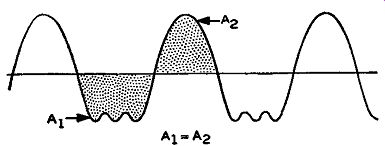
Fig. 4-39. In the stabilization system used in the Westinghouse transmitter,
if the areas of the half cycles of the FM signal, are equal (area A1
equals area A0 ), the modulated oscillator will be on the as signed frequency.
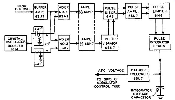
Fig. 4-40. Block diagram of the frequency stabilization system used
in the Westinghouse direct FM transmitter.
A block diagram circuit arrangement for this frequency stabilization system is illustrated in Fig. 4-40. The actual circuits are not shown in this drawing, because they are somewhat complex in operation. It is beyond the scope of this text to go into the theory of operation of such special circuits as those listed within the blocks of Fig. 4-40. In the discussion to follow we will try to make the analysis as simple as possible without deviating from the true function of each individual section of the system. To visualize the operation of this frequency stabilization system, drawings of the wave changes of certain signals as they appear throughout this system will be used. This system has been called a pulse method of frequency stabilization; this terminology will become evident as the discussion progresses.
To start with, some of the FM signal from the oscillator-tripler is tapped off the coaxial line that is used in conjunction with the audio feedback discriminator and applied to the grid of the 6SJ7 buffer amplifier, as shown in Fig. 4-40. The output of this buffer amplifier is fed into a parallel arrangement of the number one grids of two 6SA7 pentagrid tubes which act as converters. A 1614 tube is used as an electron coupled crystal oscillator and doubler. The crystal used is equal to 1/18 of the center frequency output from the transmitter.
The cathode, control grid, and screen of the 1614 tube function as a crystal triode oscillator. In the plate circuit of the 1614 tube appears a tuned circuit with a resonant frequency equal to twice that of the crystal, or 1/9 of the output frequency of the transmitter. The tube then functions as an electron-coupled oscillator and doubler with an output frequency equal to twice that of the crystal grid circuit. The output signal of this oscillator-doubler circuit is passed through two separate RC phase shift networks. At the frequency of the crystal oscillator output, the reactances of the capacitors are equal to the resistances, so that the phase shift in each case is 45°. The individual outputs of these two phase shift networks are fed into the third grids of the 6SA7 pentagrid tubes. Since two separate signals are fed into these two tubes, the latter function as mixers in which the output frequency selected is equal to the difference between the two signals.
The other frequencies that result from the mixing process are bypassed to ground through suitable capacitors. This is easily accomplished be cause the difference frequency between these two signals is very small compared with the frequency of either signal.
The RC phase shift networks are so arranged that the third grid of the No. 2 mixer tube receives a lagging 45°, and the third grid of the No. 1 mixer tube receives an input signal leading 45°, which is to say that the inputs to the third grids of the individual mixer tubes, al though equal in magnitude, differ in phase by 90°. This is an important factor in the functioning of the frequency control system, as it is the action of these mixer tubes which determines the proper operation of the rest of the circuit.
Let us now consider the operation of the mixer tubes with respect to the input voltages. First, we will consider the case when no modulation is applied to the transmitter. Since the output circuit of the crystal oscillator and the grid circuit of the master oscillator are both tuned to 1/9 of the final output frequency, then when the master oscillator is stable, the signal inputs to the first and third grids of both mixer tubes will be the same. There will be no output signal from either mixer, because the difference frequency of the two input signals is zero.
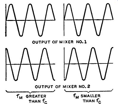
Fig. 4-41. When the instantaneous modulated oscillator frequency f M
is higher than the crystal frequency, f 0 , the output of mixer No. 1
lags that of No. 2 by 90'; and when f M is lower than f0, the output
of mixer No. 1 leads the output of No. 2 by 90°.
However, when modulation is applied, the input signal to both number one grids of the mixer tubes will be one that is frequency modulated, with the frequency varying on either side of the center frequency component. With the crystal oscillator output frequency still applied to the third grids of the mixers, these two signals will mix together, and a beat note will be produced which has an instantaneous frequency equal to the instantaneous deviation of the modulated oscillator. If the modulated oscillator is on frequency, the resultant signal will be such that the areas enclosed by the positive and negative half cycle will be equal to each other for every cycle of beat note. However, if the center frequency of the modulated oscillator drifts, the output of the mixer tubes will be such that the area en closed by the positive and negative half cycles of the resultant signal will not be equal. The rest of the control circuit, in conjunction with this difference frequency, helps keep the modulated oscillator on frequency. Each cycle of the output of mixer tube No. 2 is used to generate a pair of pulses which, after being combined with the output of mixer No. 1 and passed through a number of special circuits, produces a varying voltage on the grid of the modulator control tube of the proper potential to bring the modulated oscillator back to its correct operating point. How this is accomplished will now be seen.
Due to RC phase shifting networks, the output from the two mixers is such that, when the instantaneous modulated oscillator frequency is higher than that of the reference crystal circuit, the output of mixer No. 2 leads that of mixer No. 1 by 90°. When the frequency of the modulated oscillator is less than that of the crystal oscillator, the out put of mixer No. 2 lags the output of mixer No. 1 by 90°. In other words, at all times the output of both mixers will always be 90° out of phase, due to the phase differences in the outputs of the crystal phase shift networks. Thus, during one complete cycle of modulation, the beat note output of mixer No. 2 will lead mixer No. 1 for half the cycle, and mixer No. 2 will lag mixer No. 1 for the other half cycle.
The phase relationships between the outputs of these two mixers with respect to the frequency of the input signals is illustrated in Fig. 4-41.
In this figure fM means the frequency of the modulated oscillator and fa means the frequency of the crystal oscillator. The 90° phase relationships are readily noticed upon comparison of the respective curves.
The average beat frequency output from the mixers will not be equal during both halves of the modulation cycle when the center frequency of the modulated oscillator differs from that of the crystal oscillator. It is only upon this inequality in frequencies that a change in voltage will appear at the modulator control tube.
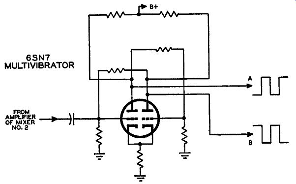
Fig. 4-42. The multivibrator circuit using a 6SN7 duo-triode with square
wave output. These square waves of opposite polarity are necessary for
the control voltage.
The outputs of these mixers are injected into separate amplifiers, each occupying one triode section of the same 6SN7 duo-triode, as shown in Fig. 4-40. The output from the amplifier of mixer No. 2 is used to trigger a direct-coupled multivibrator which uses a type 6SN7 duo-triode tube. This multivibrator makes use of the sine wave input to develop a square wave output by operating as an electronic switch, in which the multivibrator is designed to turn over very rapidly. The schematic for the multivibrator is illustrated in Fig. 4-42. The square
waves output from the plates of this multivibrator are indicated at points A and B of this schematic. These square waves are differentiated by resistance-capacitance networks to produce the pulses of opposite polarity necessary for the control voltage. These pulses, shown at points C and D in Fig. 4-43, are then combined, at the input to a pulse discriminator, with the output from the No. 1 mixer. The circuit for this arrangement is shown in Fig. 4-43. The RC differentiating networks are evident at the input to this pulse discriminator.
The pulses after differentiation of the square waves are indicated, at points C and D.
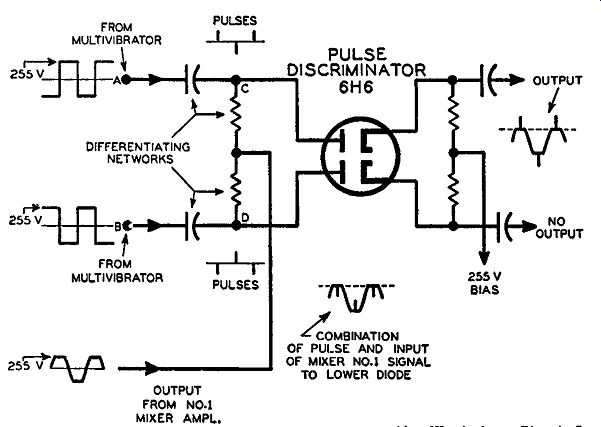
Fig. 4-43. Differentiating network with a 6H6 pulse discriminator tube
employed in the frequency stabilization system of the Westinghouse FM
transmitter, Note the waveforms and pulses at the different points in
the circuit.
With the amplifier of mixer No. 1 biased practically to cutoff, a few volts of negative signal on this grid will drive it to cutoff, in which case the plate voltage will increase very rapidly and then level off at the maximum supply voltage. But when the grid is driven in the positive direction, the plate voltage will decrease so rapidly that it will fall almost in a vertical line. On the positive half of the input signal, the grid will draw current, and a squaring effect will be the result in the output signals. The output waveform of the amplifier of mixer No. 1 is shown in Fig. 4-43 being injected into the junction of the two differentiating resistors at the plates of the 6H6 pulse discriminator.
Such a waveform is employed because only the positive half cycle of the amplifier output is made use of in the circuits to follow.
Looking at Fig. 4-43 we notice that the cathodes have a positive potential of 255 volts on them. Thus both cathodes of the 6H6 pulse discriminator are biased by +255 volts. Consequently, current will flow through either one of the diodes only when the plates are driven in excess of 255 volts positive. The amplified output of mixer No. 1 can never exceed 255 volts, so this signal alone cannot make the diodes of the pulse discriminator draw current. The same is true of the signals from the multivibrator, since the maximum positive voltage they reach is 255 volts.
However, in Fig. 4-43 it is seen that both of these voltages, namely that of the amplified output of mixer No. 1 and that from the multi vibrator, are combined at the plates of the pulse discriminator. There fore, only when these two voltages are in phase (that is, both in a positive direction at the same time) and can add up to give a greater voltage than 255 volts required for current flow, will either diode of the pulse discriminator draw current.
For the case shown in Fig. 4-43 only the upper diode section draws current, because its total available signal is momentarily greater than 255 volts positive. The input to the lower diode is such that the pulses and the output from mixer No. 1 are of opposite polarity and a signal greater than 255 volts, which is required for current flow, is not available. The combination of the out-of-phase signal inputs to the lower diode is illustrated under the pulse discriminator. Consequently, the output signal from the upper diode will be short positive pulses, as seen in the output waveform. (Although pulses riding on a squared sine wave are shown, actually only the pulses above the dashed line representing the bias level appear in the output.) The over-all function of the pulse discriminator is to produce positive pulses of voltage in the output of one tube when the instantaneous frequency is below that of the crystal oscillator, and positive pulse peaks in the other diode when the instantaneous frequency of the modulated oscillator is above the crystal oscillator frequency. The number of pulses produced depends upon the number of cycles of beat note produced by the mixer tubes. When the modulated oscillator is on frequency, the same number of pulses will be produced by each diode of the pulse discriminator. However, when the modulated oscillator shifts or drifts from its center frequency point, this equality of pulse output will no longer exist. It is this difference in pulse output that helps correct the modulated oscillator.
As shown in Fig. 4-40, the pulse output from the discriminator is sent through a pulse amplifier and a pulse limiter. These sections amplify the pulses and provide for constant equality in their amplitudes.
Next, the pulse output from these stages is applied to a pulse integrator network. This pulse integrator system takes these positive pulses of voltage and applies them as positive and negative current pulses to an integrator storage capacitor (see Fig. 4-40). These latter circuits, the pulse limiter and pulse integrator, produce current pulses as shown in Fig. 4-44 flowing through the storage capacitor. In part (A) the pulses are in the negative direction, indicating that the audio modulating signal is on the positive half cycle; in part (B) the current pulses are in the positive direction, indicating that the audio modulating signal is on the negative half cycle. Each pulse is very narrow, so that very, very small amounts of current due to these pulses flow through the integrator capacitor. This capacitor already has a fixed charge on it, and, when these positive and negative pulses flow through it, very little charging and discharging occurs, only a small variation in charge taking place. This is what happens when the modulated oscillator is practically on frequency.

Fig. 4-44. The pulse limiter and pulse integrator circuits produce current
pulses flowing through the storage capacitor of Fig. 4-40.
In conjunction with a cathode follower circuit, this integrator capacitor applies these small changes in its voltage charge to the grid of the modulator control tube. Because these differences are very small, the control voltage, when the modulated oscillator is stable, has negligible effect. However, when this oscillator drifts off frequency, the number of cycles of beat note, produced by the mixers on either side of the crystal oscillator frequency, is not equal. This means that the pulses on one side are much greater in number than on the other, and the pulses of greater number are sufficient to change the average charge on the storage capacitor until it releases a control voltage that will correct the stability of the modulated oscillator.
Accordingly as the drift is in the higher frequency direction or the lower frequency direction, the storage capacitor, in conjunction with the cathode follower, serves to produce a negative or positive voltage for the modulator control tube. By this action, the injected reactance across the modulated oscillator grid tank circuit is changed to a point where it will change the frequency of the oscillator back to its correct position.
THE REL INDIRECT FM TRANSMITTERS
The FM transmitters manufactured by the Radio Engineering Laboratories employ Armstrong's dual-channel method of indirect FM.
There is no need to go into any of the basic modulator and exciter stages, as they are the same as those discussed in connection with the Armstrong system at the beginning of this Section.
The interesting part of the REL FM transmitters is the methods of power amplification applied to FM transmitters operating on different power outputs. The same exciter unit is employed in all REL FM transmitters, as is the practice of many other manufacturers, but somewhat different methods of increasing power are employed. Most transmitters are so designed that only a power amplifier stage is added to bring a 250-watt transmitter up to a 1000-watt output. Another power amplifier stage is added to the 1000-watt transmitter to bring the power up to 3 kw, and so on up to 50 kw.
The REL transmitters, as mentioned, employ the Armstrong dual channel modulator and the same exciter stage. The output of this system is about 30 watts. For the 250-watt transmitter this 30-watt output is used to excite a push-pull pair of type 4-125A tubes for an output of 250 watts. For the 1000-watt transmitter, the same 30-watt exciter is used to drive a pair of 4X-500A push-pull power amplifier tubes for 1000-watts output. In the 3000-watt transmitter essentially the same 250-watt unit is used (the 4-125A tubes now act as an intermediate power amplifier) to drive a pair of WL 478 (push-pull) power amplifiers to obtain an output of 3 kw. The 10-kw transmitter uses the 1000-watt transmitter, and the 4X-500A tubes output of 1000 watts drives a push-pull pair of WL-479-R (final amplifiers) tubes for an output of 10 kw.
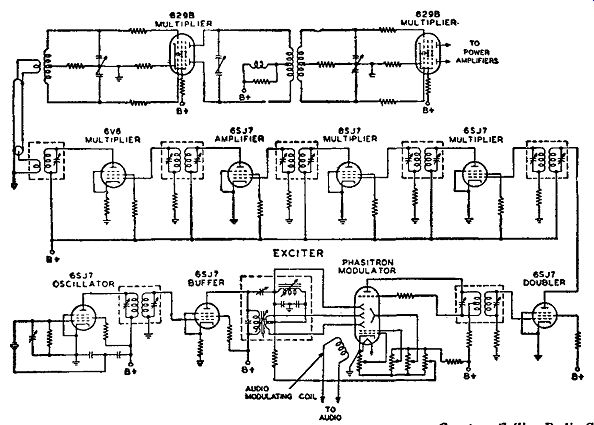
Fig. 4-45. Schematic diagram of the Collins indirect FM transmitter
using the Phasitron tube.
THE COLLINS PHASITRON TRANSMITTER
The series of FM transmitters manufactured by the Collins Radio Company employ indirect FM by the use of the Phasitron modulator tube 2H21. The circuit analysis of the exciter unit in conjunction with the multiplier stages is very similar to that of the General Electric FM transmitters which were previously discussed. A schematic diagram of the exciter and frequency multiplier system of the Collins FM transmitters 731A to 736A inclusive is illustrated in Fig. 4-45.
A distortion run taken on the model 733A 3000-watt FM transmitter for all audio frequencies showed that for audio frequencies between 50 and 15,000 cycles per second, the percentage distortion was one percent or less for 100, 50, and 25 percent modulation. The ...
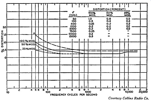
Fig. 4-46. Percentage distortion,. of the Collins FM transmitter plotted
against audio frequencies is one percent or less for 25%, 50%, and 100%
modulation.
... audio frequency versus distortion curves for these three different percentages of modulation are shown in Fig. 4-46. These curves were taken under the conditions of pre-emphasis in the transmitter and de-emphasis in the measuring equipment, and the measurements were made in accordance with FCC requirements and in FM channel 250. Curve A in Fig. 4-46 represents the maximum distortion expected with the tubes used in these transmitters. The limit of distortion for the Phasitron 2H21 tube is 1.3 percent at 50 cycles, and the three experimental curves show that the percentage distortion is below the limit of distortion allowable with these tubes.
PRE-EMPHASIS AND DE-EMPHASIS
In the audio input to a transmitter the amplitudes of the higher audio frequencies are relatively low as compared with the rest of the audio-frequency spectrum. This is due to the natural distribution of sound in radio program material, not to any characteristic of a transmitter. As the programs pass through the transmitter to the receiver and then through the receiver, noise is unavoidably added to the desired audio signal. This noise is predominantly high-frequency audio, and this condition tends to produce a low signal-to-noise ratio at the high audio frequencies because the signal is relatively weak and the noise relatively strong. In a communications system, such as commercial FM broadcasting, where the audible spectrum up to 15,000 cycles is utilized, this low signal-to-noise ratio at the high audio frequencies is most undesirable. However, it is possible to overcome this condition to a large extent by the use of pre-emphasis.
Pre-emphasis means increasing the relative strength of the high frequency components of the audio signal before it is passed into the modulator. In this way the unfavorable relationship between the high frequency program material and the high-frequency noise is changed, because while the former is increased, the latter remains the same.
Thus, the high-frequency audio signal-to-noise ratio is increased. However, at the same time that pre-emphasis is beneficial in improving the signal-to-noise ratio, it introduces a defect in that it upsets the natural balance between the high- and low-frequency tones in the program material.
This defect is compensated for at the receiver by means of a de emphasis circuit at the input to the audio amplifier. The de-emphasis circuit reduces the high-frequency audio exactly as the pre-emphasis increases it. However, it operates on both the high-frequency pro gram material and the high-frequency noise. Thus, it does not change the improved high-frequency audio signal-to-noise ratio, which is obtained by means of pre-emphasis, while it does re-establish the tonal balance of the program material, which is lost in pre-emphasis.
The pre-emphasis characteristic curve as set down by the FCC is shown in Fig. 4-47. The solid curve ideally is supposed to represent the characteristic of the pre-emphasis network used in FM broadcast transmitters. The stipulation is that audio frequencies from 50 to 500 cycles are to be flat at a no gain basis and that from 500 to 15,000 cycles the gain should increase with frequency. The increase is such that at 1000 cycles the gain is almost +1 db, at 5000 cycles the gain is approximately 8 db, at 10,000 cycles the gain is 13.5 db, and at 15,000 cycles the gain is about 17 db. All this is evident from the solid curve of Fig. 4-47 which shows how the gain at the high audio frequencies increases in order to maintain a high signal-to-noise ratio.
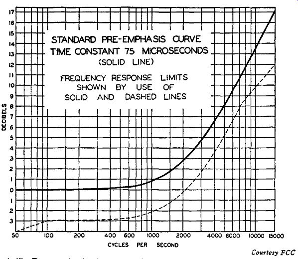
Fig. 4-47. Pre-emphasis characteristic curve established by the FCC.
The solid curve shows how the gain at the high audio frequencies increases
in order that a high signal-to-noise ratio be maintained.
When an FM signal is transmitted, it bears this pre-emphasis characteristic of the audio frequencies. This might lead to the conclusion that, since the high audios are increased to such an extent, there is the possibility of overmodulation. However, since the high audio frequency components of the actual audio signal before it enters the pre-emphasis network have a much smaller amplitude than the low audio frequencies, there is very little chance of over-modulating the FM transmitter. It should be remembered that in FM 100 percent modulation is equivalent to a peak deviation frequency of the carrier equal to 75 khz. Thus, by over-modulating we mean that the amplitude of the high audio frequency may make the final peak deviation of the carrier greater than 75 khz.
The primary reason for this pre-emphasis network is to make sure that the high-frequency components of the transmitted intelligence are not blocked out by the inherent noise characteristics at these frequencies. When this FM signal is picked up by the receiver it will have this same pre-emphasis characteristic in the intelligence it bears.
The de-emphasis network, which makes sure that the audio frequencies are returned to their original relative level before audio amplification in the receiver, is usually inserted between the detector and audio amplifier. This de-emphasis network has a frequency characteristic just the opposite to that of the pre-emphasis network. In other words its high-frequency response decreases in the same way it increases in the pre-emphasis network, In this manner, the high frequencies are brought down to their original relationship to the low frequencies. In other words the characteristic curve of the de-emphasis network should be as closely as possible a mirror image of the pre-emphasis characteristic curve.
The FCC has set a standard of a 75-microsecond time constant for the pre-emphasis network in the transmitter. (Formerly it was 100 microseconds.) Consequently, the de-emphasis network in the receiver also should have a time constant equal to 75 microseconds if it is to be the mirror image of the pre-emphasis curve.
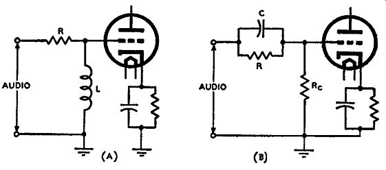
Fig. 4-48. In these two pre-emphasis networks as the audio frequencies
increase the voltage to the grids of the tubes also increases.
The FCC has established a specific time constant (75 microseconds) as good engineering practice because the most satisfactory frequency response characteristic will be obtained by that time constant. To understand what determines the time constant let us examine some typical pre-emphasis and de-emphasis networks. Two pre-emphasis networks are illustrated in Fig. 4-48. In both cases as the audio frequencies increase, the voltage to the grids of the tubes also increases.
For instance, in Fig. 4-48 (A) the total impedance to the audio voltage is given by the series combination of R and L. As the frequency increases, the inductive reactance also increases. This means that a relatively greater voltage drop will exist across the inductance at the higher frequencies than at the lower. Consequently, the voltage to the grid of the tube increases with increase in frequency. In Fig. 4-48 (B) the pre-emphasis network consisting of C and R in parallel has the same effect. The impedance offered to the audio voltage is effectively that of the parallel combination of R and C only, because the resistance of the grid resistor Re is small in comparison with either R or the reactance of C at the audio frequencies. As the audio frequency is increased the capacitive reactance of C decreases, allowing a ready path for the higher audio frequency currents as compared with the resistance of R. This means that the signal current increases with increase in audio frequency which results in a greater voltage drop across the grid resistor R0 at the higher frequencies.
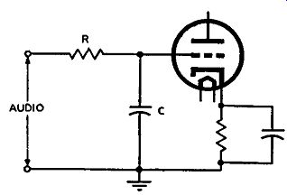
Fig. 4-49. A typical de-emphasis network as used in FM receivers. It
functions in a reverse manner to the pre-em p ha sis network, such as
is shown in Fig. 4-48.
A typical de-emphasis network is shown in Fig. 4-49 and it functions in a reverse manner to the pre-emphasis networks. The effective impedance offered to the audio voltage is the series combination of C and R. As the frequency of the audio signal increases, the reactance of the capacitor C decreases, or, as the frequency increases the reactive voltage drop decreases. The audio voltage to the grid of the tube, therefore, decreases with increase in frequency, and hence the reverse of the pre-emphasis circuit is obtained.
In order to make sure that the pre-emphasis and de-emphasis effects follow each other with respect to the increase and decrease of the relative amplitude of the high audio frequencies, the time constants of the two circuits, as mentioned, should be equal to each other.
To calculate the time constant for the networks shown in Figs. 4-48 and 4-49 is quite a simple procedure. In the resistance-capacitance networks the value of the time constant is given by R X C, where R is in ohms and C in microfarads, and the value of the time constant will be in microseconds. Thus, for a resistance of 75,000 ohms and a capacitance of 0.001 µf the time constant will be 75,000 X 0.001 or 75 microseconds. In the resistance-inductance network the time constant in microseconds is given by L/R, where L is in henrys and R in megohms. Thus for an inductance equal to 7.5 henrys and a resistance equal to 0.1 megohm (100,000 ohms) the time constant will be 7.5/0.1 or 75 microseconds.
NARROW-BAND FM
Up to this point this discussion of FM transmitters has been confined to those used for FM broadcasting. The peak frequency deviation as defined by the FCC for 100 percent modulation on the broad casting band is 75 khz. The deviation frequency is a means of establishing the bandwidth of an FM station. In all the broadcasting transmitters discussed the type of FM referred to is wide-band FM.
That is, with the peak-to-peak deviation of 2 X 75 khz or 150 khz plus the 25- khz guard bands on either side of this deviation, FM broad casting stations have an assigned band 200 khz wide. Whether the 150- khz peak-to-peak deviation is referred to as the bandwidth or whether 200 khz is called the bandwidth is of little consequence, be cause in either instance the system is referred to as wide-band FM.
In the FM transmitters used by the police, amateurs, the Army, the Navy, and the Air Force, the amount of frequency deviation of the final transmitted signal is confined to much smaller values than that used for FM broadcasting. The type of transmission used by FM transmitters operating on small frequency deviations is known as narrow-band FM The FCC has not established any ruling as to the amount of deviation to be employed for narrow-band FM as they have done for wide-band FM However, the frequency ranges allocated by the FCC and the FM receivers in use on those frequencies automatically put somewhat of a restriction on the amount of frequency deviation of the transmitted signal. Thus, although there is no legal limit to the amount of frequency deviation that can be used by narrow-band FM transmitters, a practical limitation must be taken into account. Theoretically, the amount of frequency deviation used can be as small or as great as desired, but the actual amount used is determined by a number of factors, such as the audio response required, the allowable percentage distortion, and limits as to the size and construction of the transmitter and receiver. In practice, FM bandwidths as low as 3 khz or as high as 30 khz have been used. In the former case the peak frequency deviation is 1.5 khz and in the latter it is 15 khz. Although no definite dividing line has been set, transmitters with a peak frequency deviation of more than 15 or 20 khz are generally considered medium-band, rather than narrow-band FM transmitters. We are considering only narrow-band FM at the moment.
The references to these amounts of frequency deviation are for 100 percent modulation. That is, the 75- khz peak deviation for 100 percent modulation as set up by the FCC for broadcast FM transmitters means that 75 khz is the maximum allowable peak deviation, but deviations below this are permissible. In narrow-band FM transmitters the stipulated amount of bandwidth or frequency deviation is set up by the transmitter designer or builder himself as his maximum amount of frequency deviation, and he calls this 100 percent modulation for his transmitter. This is completely different from a-m transmitters as was brought out in Section 2.
Frequency allocations for the use of FM on police bands, amateur bands, and the like, are forever changing. The FCC is constantly issuing orders with often as little as one month between them. Consequently, those frequencies that are listed in Table 4 page 182 for amateur FM transmission are the latest frequency ranges as set up by the FCC. It may be that as soon as this guide is published the frequency allocations will change. The reader is advised to keep in contact with the releases or changes of frequency allocations by the FCC before he attempts to base any design or construction work on these frequencies.
The basic circuits used in most of these narrow-band FM transmitters are similar to those already discussed. Both direct FM, employing reactance tubes of one sort or another, and indirect FM, employing crystal controlled phase shift modulators, are quite common in narrow-band FM transmitters. The types of narrow-band FM transmitters vary. Some are even so simple that they rely primarily on a reactance tube modulator circuit with the necessary amount of frequency multiplication, and no type of center-frequency control whatsoever, to obtain the final FM wave. Others are intricate enough to be almost equivalent to the operation of an FM broadcasting station, wherein a complicated phase-shift modulator is employed (indirect FM) or, perhaps, a new type of center-frequency control system for direct FM transmitters. However, so far as the production of the FM signal is concerned, the circuit analysis is practically the same as that discussed in previous Sections. In order to see this we will study some of the narrow-band FM transmitters now in use.
An Indirect Narrow-Band FM Transmitter
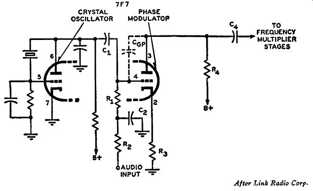
Fig. 4-50. The oscillator-modulator stage in which a 7F7 loctal tube
is used, that is incorporated in the Link UFM-Ed.7A FM transmitter. One
half the 7F7 is used as a crystal oscillator and the other half as a
phase modulator.
Many of the narrow-band FM sets used by the police and taxicab companies as mobile equipment and also the sets employed by the Armed Forces utilize direct FM and indirect FM (p-m) circuits similarly to sets already discussed. The Link Radio Corporation of New York has manufactured a number of different types of mobile and fixed-station FM transmitters for the police and Army and Navy.
In many of these transmitters indirect FM is employed, wherein an initial p-m signal is made equivalent to an FM signal by the use of an audio frequency correction network. In most of the Link FM transmitters in use today, a different type of modulator circuit from those previously discussed is employed. The modulation process is one of indirect FM, where a shift in phase is the basis producing a modulated signal. By the use of an audio frequency correction network, the p-m signal is made equivalent to an FM signal. The important thing about this system is that, for the audio frequencies involved, quite a large initial phase deviation can be obtained, and consequently the use of a small amount of frequency multiplication is needed. In Fig. 4-50 appears a typical schematic diagram of the phase modulator circuit. This circuit is used in the UFM-Ed.-7A Link transmitters as well as other sets. The complete oscillator-modulator circuit uses only a single tube - the duo-triode 7F7 !octal tube. One half of the 7F7 is used as a crystal oscillator, and the other half is used as a phase modulator, The crystal oscillator uses the triode section connecting to pins 5, 6, and 7 of the 7F7 tube and is of the resistance-capacitance coupled type commonly known as the Pierce crystal oscillator. The functioning of this modulator is based upon the variation of the transconductance or g,,. of the tube with the amplitude of the audio input. To understand fully the functioning of this modulator system we will analyze it in conjunction with a vector diagram. The vector diagrams for this circuit are in Fig. 4-51. With the proper supply voltages on both triode sections of the 7F7 tube, and without any audio applied to the modulator, the system functions as follows: The oscillator injects an r-f voltage into the grid circuit of the modulator, pin 4, through the coupling capacitor C 1 From this grid circuit, the r-f energy from the oscillator section is split up in two paths. Part of this r-f signal finds its way to the plate of the modulator through the grid to plate interelectrode capacitance Cap, and part across the grid impedance network of the modulator tube. This latter voltage is amplified by the tube and finds its way to the plate of the modulated tube in the form of an amplified r-f signal. The voltage appearing on the plate of the modulator tube by amplification is referred to as the voltage due to the gm of the tube. Owing to the inherent nature of an amplifying vacuum tube, the amplified voltage appearing on the plate of the tube is 180° out of phase with that appearing on the grid of the same tube. Under ideal conditions the r-f voltage fed through Cap from the grid to the plate of the modulator, would be 180° out of phase with the voltage existing there due to the amplification of the tube. But the value of the interelectrode capacitance is small, and a small phase shift occurs in the r-f voltage passing through Cap, Therefore, the two separate voltages appearing at the plate of the modulator tube, effectively across the plate load resistor, R4, are not exactly 180° out of phase. This is best indicated by the vector diagram of Fig. 4-51 (A) where voltage vector EG is that due to the transconductance of the tube and voltage vector Ee is that due to the grid to plate interelectrode capacitance of the tube. Since these two voltages exist at the same point, they effectively combine to give a resultant voltage. This is shown by the vector addition of EG and E0 in Fig. 4-51 (A), where vector EB represents the resultant vector. Due to the amplification of the tube the voltage Ea would ordinarily be much greater than voltage Ee. However, the value of Ea is limited by the degenerative feedback (that is, inverse feedback) that occurs in the modulator tube. This degenerative feed back is due to the cathode resistor R3 being unbypassed and, there fore, allowing all the amplified r-f current to flow through R3, effectively causing a smaller r-f voltage to appear across the grid circuit of the modulator tube. The components are so chosen that the magnitudes of voltages Ee and EG are approximately equal. This is indicated by the magnitudes of the voltage vectors Ee and Ea of Fig. 4-51 (A) being equal.
From this vector diagram, it is seen that, without any audio applied to the modulator tube, the phase of the resultant voltage, EB in Fig. 4-51 (A), appearing across the plate load of the modulator tube will have a phase theta_1. If either vector Ee or vector Ea is changed in magnitude, the resultant vector E:a will shift in phase, and by this method the resultant output signal of the system will be phase-modulated.
This is what happens when an audio signal is applied to the grid of the modulator tube through resistors R1 and R2 as seen in Fig. 4-50. The audio voltage varies the instantaneous bias on the modulator grid which, in turn, varies the transconductance of the tube in accordance with the varying amplitude of the audio signal at a rate determined by the audio frequency. This change in gm varies the voltage EG on the plate of the modulator. When the audio signal is on the negative half cycle, the grid will have a more negative bias, and the value of EG decreases in accordance with change in bias. This is indicated in Fig. 4-51 (B) where vector Ea is seen to be smaller than the previous vector E0 in Fig. 4-51 (A). The phase relationship between Ee and Ea does not change. Only the magnitude of Ea changes. In turn, resultant vector ER due to the vector addition of Ee and EG also changes.
The phase angle is increased in the positive direction, and the new phase angle is designated as Os (where Os is greater than Oi) in Fig. 4-51 (B). When the audio signal is on its positive half cycle, the grid bias will become less negative, and consequently the value of EG on the plate of the tube increases in accordance with the change in bias. This in crease in EG is illustrated in the vector diagram of Fig. 4-51 (C). The Fig. 4-51. Vector diagrams of the voltage relationships in the circuit shown in Fig. 4-50.
phase relationship between E_C and E0_G still remains the same, but the resultant voltage vector E_R, due to the vector addition of E_C and E_G, changes. From Fig. 4-51 (C), this change ,s seen to cause a decrease in the phase angle of the resultant vector ER. The new phase angle is designated as theta_3. It will be noted that 03 is smaller than 01. From these vector diagrams it is readily seen that the resultant voltage across the tuned load of the modulator tube is varied in phase about its steady state (that is, no audio applied) phase value of theta_1 and, hence, the crystal carrier frequency is phase modulated. The magnitude of the phase change, or phase deviation, is dependent upon the amplitude of the audio modulating signal; and the rate of change of the phase deviation is dependent upon the frequency of the audio signal. Since the audio input is impressed across the modulator grid through an audio correction network, consisting of resistor R? and capacitor C,, the p-m signal is made equivalent to an FM signal.
The discussion of frequency multipliers operating as class C amplifiers, mentioned that an inherent fundamental action of this type of amplifier is that besides acting as harmonic generators they also act as amplitude limiters. Thus, if any a-m effects happen to be super imposed upon the FM or the p-m signal before it reaches the frequency multipliers, the multipliers, provided the signals are not too strong, will be able to eliminate these amplitude variations success fully. This is what happens in this transmitter. Glancing at the vector diagrams of Fig. 4-51, it will be noticed that besides varying phase, the resultant vectors ER also varies in amplitude. These amplitude variations are in accordance with the audio amplitude, but are eliminated by the limiting action of the frequency multiplier stages which follow. Consequently, the final FM signal will be virtually free of any amplitude effects.
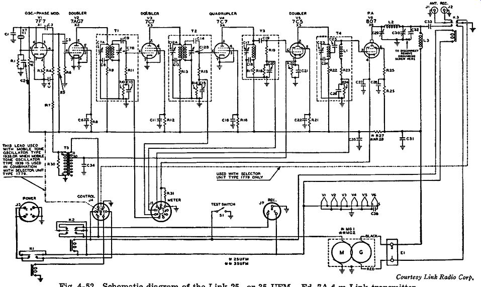
Fig. 4-52. Schematic diagram of the Link 25- or 35-UFM - Ed. 7A FM Link
transmitter.
The amount of frequency multiplication employed in these transmitters is 32 times, and the final peak frequency deviation is equal to 15 khz for 100 percent modulation throughout the audio range. This means that the initial peak phase deviation of the modulator is equivalent to a frequency deviation of 15 khz/32 or approximately 470 cycles per second. This initial equivalent frequency deviation may appear to be quite large for a phase modulator until one considers that an audio frequency range of only 350 to 5000 cycles per second (more than sufficient for speech work) is involved. Recognizing this, the initial amount of peak phase deviation for the smallest audio frequency will not be so great as in indirect FM broadcast transmitters.
In this instance the initial peak phase deviation P_D for the smallest audio frequency of 350 cycles is equal to the following:
P 57.3 X F D = 350 I>
…where F_D equals the peak frequency deviation, in this case equal to 470 cycles per second, and where 57.3 is the number of degrees in one radian. Therefore, Pv = ~~-; X 470 = 76.9 degrees.
This is still quite a large phase deviation but not so great as at first indicated by the equivalent peak frequency deviation. At 350 cycles the audio frequency response of the transmitter is down 2.5 db as compared with the middle of the audio band. However, at 500 cycles the audio response is down only 1 db, and at this audio frequency, for a final output peak frequency deviation of 15 khz for 100 percent modulation, the initial amount of peak phase deviation of the modulator would have to be Pv = !~-; X 470 = 53.8 degrees
Even at the higher frequency of 500 cycles, this initial amount of phase deviation is quite large compared with that for some FM broadcasting stations employing indirect FM, where the smallest audio frequency involved has to be, at the most, 50 cycles per second and where the initial amount of peak phase deviation may be in the vicinity of 25 degrees.
These transmitters can be operated anywhere in the 30-to-44 -mhz range and, since the frequency multiplication is 32, the crystal used for the oscillator will be anywhere between 30 mhz/32, or 937.5 khz, and 44 mhz/32, or 1375 khz. A schematic diagram of the 25- or 35-UFM Ed. 7 A FM Link transmitter is shown in Fig. 4-52.
Amateur FM This part of the narrow-band FM transmission is probably of great interest to those contemplating rigging up a ham FM station, or to those hams who have already built a set and are confronted with changing frequency allocations. At the time of this writing not too many companies have amateur FM transmitters on the market, al though a great many are in the process of building them. It is difficult to make any predictions about the types of modulator circuits that will be employed in the ham transmitters being built, but it is believed that the circuits used for the production of the FM signals will be very similar to those discussed in this guide, as are most of the ham FM transmitters now on the market. The greatest striving toward new developments will be toward different and better types of frequency control circuits for direct FM transmitters and for better noise, distortion, and audio characteristics in both the direct and in direct FM transmitters.
In Table 4 is a listing of the frequency assignment in which amateurs are allowed to operate on FM This list is not inclusive of FM alone. Most other types of emission ( except television in most in stances) are also included.
TABLE 4. FCC Frequency Range
.... in Which Amateur FM Can Operate 3.85 mhz to 3.9 mhz 1,215 mhz to 1,295 mhz 14.2 mhz to 14.25 mhz 2,300 mhz to 2,450 mhz 27.160 mhz to 27.430 mhz 3,300 mhz to 3,500 mhz 28.5 mhz to 29.7 mhz 5,650 mhz to 5,850 mhz 51.0 mhz to 54.0 mhz 10,000 mhz to 10,500 mhz 144 mhz to 148 mhz 21,000 mhz to 22,000 mhz 235 mhz to 240 mhz and 420 ma to 450 mhz All frequencies above 30,000 mhz.
* As of October, 1947.
Table 4 is tabulated from a compilation of data received from the FCC, and its last effective date was in October 1947. There is only one limitation in this listing, and that is the peak antenna power on the 420-to-450 -mhz band shall not exceed 50 watts. All the bands, 420 to 450 mhz and higher, can also include television, and the bands, 1,215 to 1,295 mhz and higher, can also employ pulse emission:$. A quick survey of this table indicates that the range of frequencies in each band increases as the relative frequencies themselves increase. It is believed that many ham transmitters will contain provisions for switching over into different bands, so that operation will not be restricted to only one band.
An Amateur Direct FM Transmitter
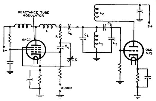
Fig. 4-53. Simplified schematic diagram of the FM oscillator and modulator
stages of the Supreme AF-100 transmitter.
In the model AF-100 of the Supreme Transmitter Corporation of New York both AM and FM are employed. This transmitter can operate on a-m telephony, FM telephony, continuous wave telegraphy, and modulated continuous wave telegraphy. It employs a direct FM system using a 6AC7 single reactance tube modulator in conjunction with a 6J5 variable oscillator. The oscillator-modulator circuit arrangement is shown in Fig. 4-53 in simplified form. This reactance tube modulator is similar to that shown in Fig. 3-7 (B) in Section 3, where the capacitance C and the resistance R are the primary determining elements for the amount of injected reactance, which is inductive in this case. Coil L is inserted between the plate of the 6AC7 modulator tube and the resistance R, so that in conjunction with C and R the modulator tube will act as a quadrature tube. In other words, L, C, and R together function as the phase-shifting network in which inductive reactance is injected across the oscillator tank circuit consisting of coil L1 and capacitors C1, C,, and C,. The type of oscillator circuit used is an ordinary tuned-grid tickler-coil oscillator in which the tickler coil, L2, in Fig. 4-53, is in the plate circuit of the 6J5 oscillator tube. The coupling between the two coils L1 and L2 is just enough to maintain stable oscillations. Fig. 4-53, shows that both audio voltage and r-f voltage from the oscillator tank are applied to the control grid of the 6AC7 reactance modulator. The r-f voltage to this grid can be varied by the capacitor C. The variable frequency oscillator can be tuned anywhere within the range of 3.4 to 4 mhz. The band selector switch is so arranged that the necessary frequency multipliers are inserted in the circuit, so that the output FM signal will be within the limits allowed by the FCC. The volume level of the audio input to the reactance tube can be controlled, so that frequency deviations from narrow-band to wide-band FM are obtainable. This variable deviation allows operation with most types of receivers, regardless of their particular type of circuit. For in stance, for a straight FM receiver working on the amateur bands the tuning is usually broad band, so that a wide frequency deviation is needed. However, one o4' the main purposes of narrow-band FM is to make most ham superheterodyne a-m receivers accept the FM signal and detect it satisfactorily.
At this point it might be wise to show how an a-m receiver can be put to use in detecting narrow-band FM signals. To start with, most a-m intermediate frequency transformers have a selectivity characteristic similar to that shown in Fig. 4-54. The peak of the curve is at the frequency of the i-f signal. The shape of the curve is such that points A and B, where the output voltage for a constant-voltage, variable-frequency input signal is about 0.7 of the maximum amplitude, are the usual design points for the proper reception of a-m signals. These points are called the "half power points" of the i-f curve. An a-m signal of the correct i-f will be passed by the i-f trans former. If a narrow-band FM signal with a peak-to-peak frequency deviation up to about 4 khz were to be received, by proper manipulation of the tuning control, it could be successfully detected by the a-m receiver. This is explained as follows: In order to make sure that the narrow-band FM signal is passed by the i-f transformer, and also to make sure that distortion is a minimum, so that the FM variations can be changed into a-m variations for detection, the receiver is slightly detuned. The amount of detuning is such that the reproduction of audio will be at its best.
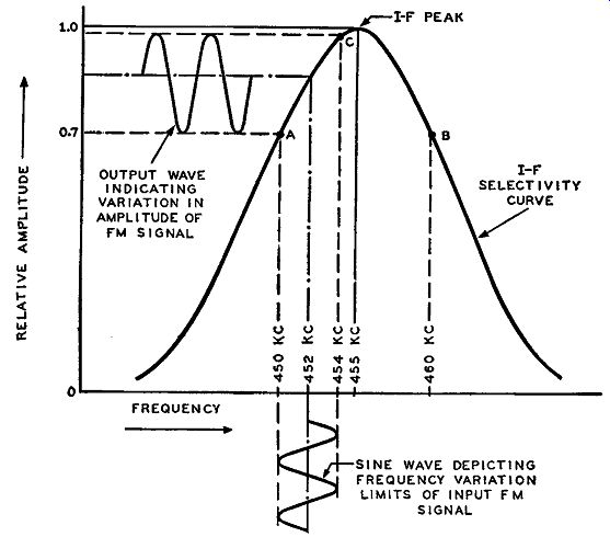
Fig. 4-54. The effect of a typical i-f selectivity curve of an a-m receiver
on an FM signal.
By slightly detuning the set, the r-f section and the oscillator section both become detuned. The amount of r-f detuning is, however, slight, and the FM signal voltage still comes through. The oscillator becomes detuned to a point where it will produce an i.f. that is different from the peak frequency of the i-f transformer. If the detuning is such that the peak of the new i-f signal lies on the linear portion of the transformer characteristic on either side of the transformer peak, the FM signal will be properly detected. For the sake of argument let us say that with detuning the oscillator frequency is decreased by 3 khz. Assuming that the oscillator is tuned above the incoming signal the output i-f signal from the converter system will be equal to 452 khz instead of 455 khz. Now, with the peak frequency deviation of the narrow-band FM signal equal to 2 khz, the i-f signal will be changing in frequency from a minimum of 450 khz to a maximum of 454 khz.
Since the i-f transformer has a band width of 10 khz, this FM i-f signal will be accepted by the transformer. The signal at the bottom of the drawing is supposed to represent only the frequency variations of the FM signal between its limits of 450 khz to 454 khz. The upper signal shows how these frequency variations, which are varying at an audio rate, cause amplitude variations due to the so-called slope of the r-f curve. Both the input and output signals from the i-f trans former are FM signals, but the transformer characteristic has incorporated amplitude variations into the output FM signal, these amplitude variations changing in accordance with the audio intelligence of the FM signal. Consequently, when the output signal from the i-f transformer is sent through the a-m detector stage of the receiver, the detector will respond to the amplitude changes (but not to frequency changes), so that these amplitude changes will be detected. Therefore, the audio signal reproduced by the detection of the amplitude variations will contain the intelligence of the FM signal.
Due to the peak frequency of the operating i-f signal, the part of the i-f curve used in this example that will accept this FM r-f signal will be that portion between 450 and 454 khz. Looking at Fig. 4-54, this portion of the curve is seen to be quite linear. Therefore, with the FM signal changing in frequency between these two limits, the i-f transformer will reproduce these frequency variations, which are at an audio rate, with a minimum amount of distortion. In other words, the more linear the portion of the curve between points A and C becomes, the less distortion will appear in the output.
If the set is rot detuned and a narrow-band FM signal is received, the oscillator will beat with the incoming FM signal to produce an i-f FM signal that is exactly on the peak of the i-f transformer. If the peak-to-peak deviation of the FM signal is equal to 4 khz and if the i-f peak is equal to 455 khz, the i-f FM signal is swinging from a minimum frequency of 453 khz to a maximum of 457 khz due to the 2- khz peak deviation. This signal will pass through the i-f transformer be cause it is well within the bandwidth of the FM signal. However, the way it now stands the FM signal in passing through the i-f trans former will produce an output that is badly distorted because the signal will be working on a very nonlinear portion of the i-f characteristic, namely the portion of the i-f peak.
If the FM signal had a much wider bandwidth, it would be difficult to reproduce this FM signal on an a-m set without much distortion. The i-f transformers would require special wide-band characteristics greater than 10 khz.
A Direct P-M Exciter
In the narrow band FM exciter Model VFX 680 of the Sonar Radio Corporation of Brooklyn, N. Y., is employed a type of phase modulator similar to that explained in the discussion of the Link transmitters. The actual circuit as used in this exciter is shown in Fig. 4-55.
They use a 6AG7 as a crystal oscillator and one half of a 6SL7 as a phase modulator. The underlying theory of producing the p-m signal is essentially the same as that previously analyzed in conjunction with Figs. 4-50 and 4-51. That is, the oscillator signal appears on the plate of the modulator tube through two sources, one through the grid to plate interelectrode capacitance and the other due to the amplification of the tube. Both of these voltages are somewhat less than 180° out of phase with each other and about equal in magnitude. The resultant signal on the plate is approximately in quadrature (90° out of phase) with the grid voltage. With an audio signal applied to the modulator grid the gm or transconductance of the tube varies at an audio rate, and, hence, that voltage on the plate of the modulator due to the amplification of the tube varies at this audio rate. Consequently, the resultant voltage at this modulator plate varies in phase at an audio rate and, hence, the signal output from the modulator is phase modulated.
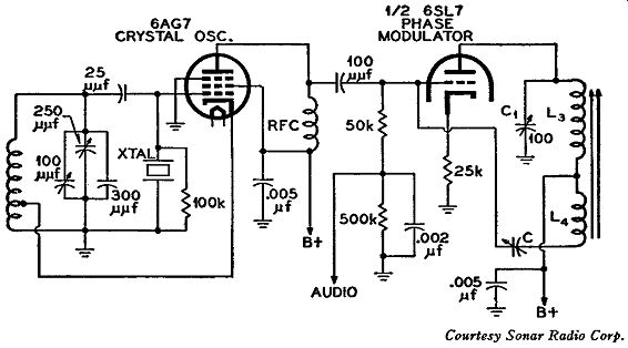
Fig. 4-55. The schematic of the crystal oscillator and phase modulator
circuits used in the Sonar narrow-band FM exciter Model VFX 680. The
circuit of Fig. 4-55 is a little different in that variable capacitor
C in conjunction with inductance L4 is inserted to be able to adjust
the phase and magnitude of the voltage acting between the grid and plate
of the modulator tube. By this method it is possible to increase the
phase shift and, hence, the phase deviation of the resultant signal.
If the inductance contains a powdered-iron core and if C1 is variable, the phase shift can be further increased. The characteristics of the powdered-iron slug are such that the d-c plate current of the tube, when varied at the audio rate while passing through the coil, introduces an additional phase shift.
The interesting thing about this exciter unit is that it does not use any means to make the p-m signal directly equivalent to an FM signal (that is, it does not use any audio correction network). Consequently, the output signal is one of direct p.m. This is the only transmitter discussed in this text that has its output signal directly phase modulated. The maximum peak phase deviation swing for this exciter is equivalent to a maximum peak deviation swing of about 1.5 khz at 350 cycles. This deviation can be controlled by a potentiometer in the input of the audio amplifier, and thus, according to the amount of frequency multiplication used on the different amateur bands, the final deviation output can be controlled to the desired narrow bandwidth, which can be detected by an a-m superheterodyne receiver.
It has been found by field tests that two very closely separated FM signals (2 khz apart) can be operated simultaneously without causing the usual splatter of interference often found in the case of AM Phase modulated signals have been known to give less audio distortion duo to selective fading than other types of modulation.
An interesting part of this exciter unit is the crystal oscillator circuit shown in Fig. 4-55. This type of circuit is commonly known as a "rubber crystal" oscillator circuit. That is, with the crystal inserted, the circuit can be tuned through a certain range of frequency. This means that the circuit exhibits the stability of a crystal oscillator and also the effects of a variable frequency oscillator. The frequency of the crystal chosen is the lowest frequency of the band desired, be cause in tuning this rubber crystal oscillator the variation will be such that the oscillator can only tune above the frequency of the crystal.
QUESTIONS
SECTION 4
4-1. What relationship must exist between the resistance and capacitance of audio correction network in an indirect FM transmitter in order to make the current flowing in it independent of frequency?
4-2. Referring to the circuit of Fig. 4-2 :
a. What is the primary purpose of this balanced modulator circuit?
b. What are some of the critical factors in the proper balancing of the circuit?
c. What function do capacitors C2 and C3 serve?
d. What is the purpose of resistors R2 and R3?
4-3. What is the phase relationships between the primary current and secondary current, and between the primary voltage and induced secondary voltage in an untuned transformer?
4-4. If the tuned primary of a transformer is in series resonance at some particular frequency and the secondary is untuned, what is the phase relationship between the primary voltage and secondary voltage at this resonant frequency?
4-5. a. Compare the amplitude and frequency of the center frequency component of the FM signal at the input to the first tripler stage (that is, at the output of the modulators) of each frequency multi plier system in the Armstrong dual-channel transmitter. b. What is the phase relation between the frequency deviation of the FM signal input to each multiplier system?
4-6. If the frequency of the master crystal oscillator in the Armstrong dual-channel transmitter is equal to 205.00 khz and the original amount of peak frequency deviation equal to 12.50 cycles, then, referring to the FM signal output of the last triplers of the dual channel chain (before the double conversion system):
a. What is the center frequency component of the FM signal?
b. What is the peak deviation of the FM signal?
4-7. Upon what oscillator in the Armstrong dual-channel transmitter does the output frequency from the double conversion system chiefly depend?
4-8. Referring to Fig. 4-4, what would be the center frequency component and peak deviation frequency of the FM signal output from the double frequency conversion system if the frequency of the master oscillator and original peak deviation frequency were changed to 205.00 khz and 12.50 cycles respectively?
4-9. If only the crystal frequency of the double conversion system of Fig. 4-4 is changed from 918.75 khz to 907.5 khz, what will be the center frequency component output from both the old band multiplier and the new-band multiplier chain?
4-10. a. Compare the connections of the control grid circuits and also the plate circuits of the balanced modulators of Fig. 4-2 and Fig. 4-5. Give your answers in terms of parallel and push-pull connections.
b. Which would be the more correct designation than "balanced modulators" for the circuits of Fig. 4-2 and 4-5: balanced frequency modulators, balanced phase modulators, or balanced amplitude modulators?
4-11. a. What relationship must exist within the circuit of Fig. 4-6 (A) to make the currents I_1 and I_2 practically 90 degrees out of phase with voltage E1 and E2 respectively.
b. Why are voltages E Rt and E Ri, which are applied to the control grids of the modulator tubes of Fig. 4-6, each shifted in phase by 90 degrees with regard to the crystal carrier voltages E 1 and E8 respectively?
4-12. Refer to the circuit of Fig. 4-8. If the resonant frequency, f, of both a series tuned and a parallel tuned circuit is given by 1 f=-- 2 pi LC where L is the total effective inductance and C the total effective capacitance:
a. What is the correct resonant frequency formula for the parallel resonant circuit that exists between the grids of both tripler tubes? Use the circuit component symbols in the drawing.
b. It is stated in the text that this parallel resonant circuit can also be considered to consist of two series resonant circuits in parallel with each other, each resonant at the same frequency, which is also the resonant frequency of the parallel tuned circuit. What is the formula for the resonant frequency of each of these series tuned circuits? Use the circuit component symbols in the drawing.
4-13. How are the voltages of crystal carrier frequency which are applied to the tripler grids of the circuit of Fig. 4-8 made equal in magnitude and 180 degrees out-of-phase with each other?
4-14. a. What is the phase relationship between the double sideband voltage applied to each tripler grid of Fig. 4-8? b. Why are the magnitudes of the double sideband voltages applied to the tripler grids very much smaller than those of the crystal frequency signals with which they are recombined at the tripler grids?
4-15. Regarding the block diagram of the Western Electric FM transmitter shown in Fig. 4-11, then:
a. For a transmitted frequency of 100 mhz ±75 khz peak deviation, explain why the input frequency to the buffer is equal to 6.25 mhz ±4.6875 khz.
b. If the transmitted frequency is to be 107.2 mhz ±75 khz, what will be the required center frequency component and peak frequency deviation of the FM signal input to the buffer or multiplier stages?
c. If the output FM signal from the fourth doubler has a frequency of 94.372 mhz ±77 khz, what is the center frequency component and frequency deviation of the FM signal output from the frequency divider stages?
4-16. What is the purpose of the frequency dividing system used in the Western Electric FM transmitter?
4-17. What happens in the Western Electric FM transmitter when the output signal from the WE 349A amplifier in the frequency divider section is of a different frequency from that of the crystal oscillator?
4-18. In the circuit of Fig. 4-12, how are the plates and control grids of the reactance tube modulators connected with respect to r.f.? Give your answers in terms of parallel and push-pull connections.
4-19. In the circuit of Fig. 4-12:
a. What is the phase relationship between the plate current of the top modulator tube and the voltage at the top of L1, and also be tween the plate current in the lower modulator tube and the voltage at the bottom of L1?
b. What type of reactance is injected into the oscillator tank circuit from the upper modulator tube? From the lower modulator tube?
c. When the applied audio signal is such that the gm of the lower modulator tube increases, what happens to the injected inductance and capacitance from the lower and upper modulator tubes? Do these changes in reactances increase or decrease the oscillator frequency?
d. The increasing amplitude of an audio modulating signal increases the amount of frequency swing of an FM signal. Is the required amplitude of the audio modulating signal in the balanced modulator circuit under discussion less than, more than, or the same as that which would be needed for a single reactance tube circuit to produce the same amount of frequency deviation with respect to the same oscillator circuit?
4-20. In the CBS direct FM transmitter as shown in block diagram form in Fig. 4-15:
a. If the frequency of the master oscillator is changed to 5.861 mhz, what must the crystal oscillator frequency be to maintain the 3-mhz FM i-f input to the discriminator of the automatic frequency control system?
b. If the master oscillator frequency remains at 5.617 mhz, what must the frequency of the crystal oscillator be if the FM i-f output of the mixer is changed to 1 mhz?
4-21. Why is the initial amount of peak frequency deviation of the master oscillators of both the CBS and NBC new direct FM transmitters the same for 100-percent modulation, even though the center frequencies of the master oscillators are not the same?
4-22. If the output from the new-band NBC FM transmitted were changed to 91.8 mhz, what would be the center frequency component of the FM signal output from the fourth divider?
4-23. a. Is the electron disk of the Phasitron tube a physical part of the tube? Explain briefly.
b. What causes the electron disk to take on the sinusoidal shape indicated in Fig. 4-21.
4-24. a. What are the two functions of the second focusing electrode of the Phasitron tube?
b. What is done to the modulating coil in order to have the output signal from the Phasitron frequency modulated?
4-25. If the FM signal output from the last multiplier tube of Fig. 4-24 is desired to be 89.2 mhz ±75 khz, what can be done within the multiplier system to produce this new signal output while still maintaining the output of the Phasitron at 225 khz ±173.6 cycles.
4-26. Briefly explain the Miller effect and how it is put to use in causing a capacitance to be injected across the master oscillator tank circuit in the Federal Telephone and Radio Corporation's FM transmitter.
4-27. Regarding the circuit of Fig. 4-26:
a. If the effective load impedance in the plate circuit of the 6AB7 modulator tube is made purely resistive, what is the only variable component upon which the injected capacitance will depend, assuming all the circuit capacitances are fixed?
b. How is the plate load of the modulator tube made purely resistive?
c. Why is the resistor inserted across the parallel tuned network in the plate circuit of the modulator tube?
4-28. If an r-f VTVM measures 4.5 volts between grid and ground of the modulator tube of Fig. 4-26 and measures 72.9 volts when placed between plate and ground:
a. Compute the value of the grid input capacitance, C1, of the circuit.
b. Compute the value of the total capacitance injected across the cathode tap of the oscillator tank coil.
c. Compute the amount of peak frequency deviation under theoretical sensitivity conditions.
d. What is the amount of peak frequency deviation under experimental sensitivity conditions? Use the proper graph, Fig. 4-27 for this.
4-29. Why are the frequency limits of the master oscillator of the Federal FM transmitters between 3.66 and 4.5 mhz?
4-30. Regarding the Federal FM transmitter:
a. If the master oscillator has a frequency of 4.1 mhz, what is the final transmitted frequency? What is the frequency input to the phase discriminator from the divider system?
b. What is the required resonant frequency of the crystal (in the frequency dividing section) if the master oscillator has a stable frequency of 4.1 mhz?
4-31. If the master oscillator drifts in frequency so that the voltages applied to the upper diode section of the 12H6 phase discriminator of Fig. 4-29 (in the frequency control system of the Federal transmitter) increases, in which direction has the master oscillator drifted-toward a higher or a lower frequency? Explain your answer.
4-32. a. In the Raytheon indirect FM transmitter, six cascaded phase modulators are used. Each stage handles an r-f and an audio signal. To which signal are the modulators connected in cascade?
4-33.
4-34.
4-35.
4-36.
4-37.
4-38.
b. How is the other signal injected in the modulators? If the amount of peak phase deviation of one phase modulator of the Raytheon FM transmitter were 19.1 degrees instead of 25 degrees, what would be the peak frequency deviation of the FM output from the last tripler multiplier of Fig. 4-31 for the same audio frequency of 30 cycles? If the inductive reactance of L in Fig. 4-32 is equal to half the reactance of C at the frequency of operation, what is the phase relationship between the total current I flowing in the circuit and the voltage across it when:
a. The resistor R has infinite resistance?
b. The resistor R has zero resistance? In the Westinghouse FM transmitter, how is B-plus voltage supplied to the plate of the 1614 modulator control tube? The vector diagram of Fig. 4-37 shows that the current I flowing in the circuit at different instants of applied audio contains both a resistive and a reactive component. Both components are effectively injected across the oscillator circuit. Since an injected varying resistive effect will cause AM of the oscillator, explain how such a-m effects are made negligible in the Westinghouse transmitter.
What is the purpose of the audio feedback discriminator network of the Westinghouse FM transmitter? In the frequency stabilization circuit of the Westinghouse FM transmitter, what is the phase relationship between the outputs of the two 6SA7 mixers illustrated in Fig. 4-40 when:
a. The instantaneous modulated frequency of the master oscillator is lower than the crystal oscillator frequency?
b. The instantaneous modulated frequency of the master oscillator is higher than the crystal oscillator frequency? 4-39. a. What does a pre-emphasis circuit do to the audio signal?
b. Why is it employed in FM transmitters?
c. What is the purpose of the de-emphasis circuit in FM receivers and where is it usually placed? 4-40. a. What is the time constant of the pre-emphasis circuit in Fig. 4-48 (B) when resistor R equals 220,000 ohms and capacitor C equals 330 µµf.
b. What is the time constant of the de-emphasis circuit in Fig. 4-49 when resistor R is equal to 160,000 ohms and C equals 470 µµf?
c. What is the standard time constant for pre-emphasis circuits as prescribed by the FCC?
d. What is the standard time constant for de-emphasis circuits?
4-41. For narrow-band FM transmitters, what is considered 100-percent modulation?
4-42. Why is it possible to obtain a much larger initial amount of equivalent frequency deviation in most of the indirect narrow-band FM transmitters than with indirect FM broadcasting transmitters, even when the initial amount of phase deviation is the same?
4-43. Considering the circuit of Fig. 4-50:
a. By what two paths does the r-f oscillator signal that exists at the grid of the modulator find its way to the plate of this modulator tube? b. Why is resistor R3 not bypassed?
4-44. From the vector diagrams of Fig. 4-51, it can be noticed that the resultant p-m signal, ER besides varying in phase, in each instant also varies in amplitude. How are these amplitude variations eliminated in the Link transmitter?
4-45. When using an a-m receiver for reception of narrow-band FM signals:
a. What must be done to the a-m receiver to reproduce the best possible FM signal?
b. What is the modulation characteristic of the output signal from the i-f transformer?
c. Why will the reproduced signal be distorted when the set is not detuned?
4-46. a. What is meant by a "rubber" crystal oscillator circuit?
b. To what frequency is the crystal cut in a "rubber" crystal oscillator circuit? Why?