Phase-locked-loop circuit upgrades older stereo tuners and receivers.
BY MARTIN MEYER
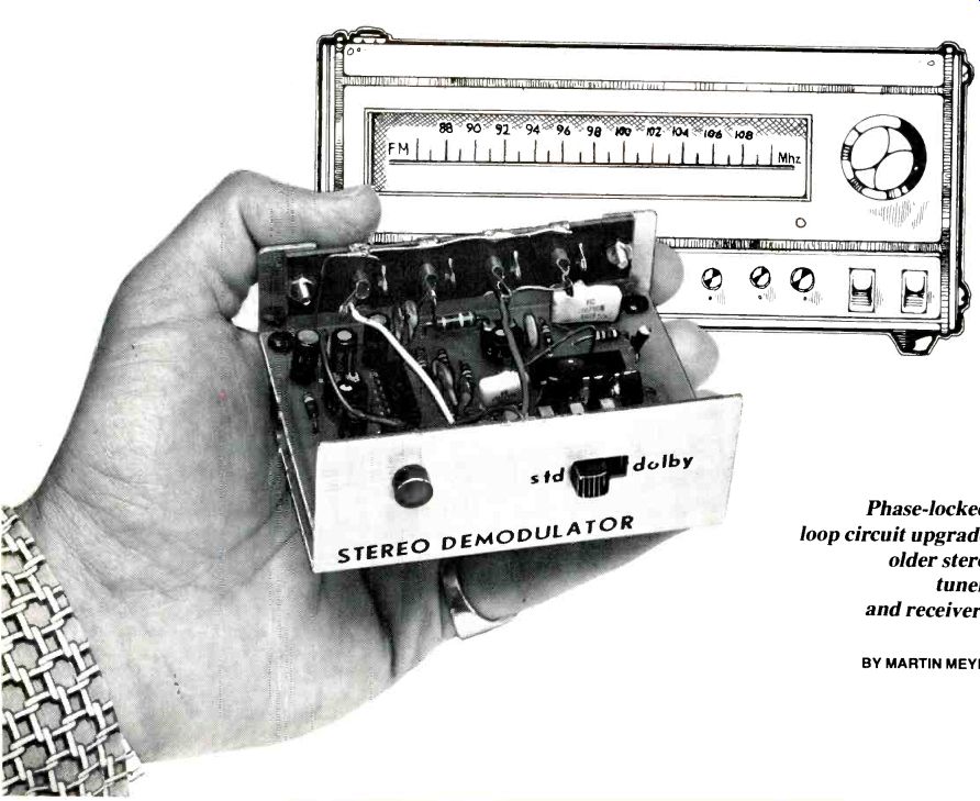
TODAY'S state-of-the-art audio components yield levels of performance unattainable a few years ago. However, most of us can't update our sound systems as frequently as technological advances are made. This project-an add-on phase-locked-loop multiplex decoder-will allow the user to improve the stereo FM demodulation of an existing receiver or tuner for about $25. Only a few hours of assembly and alignment time is required. The PLL decoder will not only improve channel separation and lower distortion levels, but will also select de-emphasis time constants for standard and Dolby-FM broadcasts.
About the Circuit. The heart of the PLL multiplex demodulator is the LM1800A, an IC manufactured by National Semiconductor. A block diagram of the LM1800A is shown in Fig. 1. The phase-locked loop comprises a voltage controlled oscillator (vco), frequency dividers, phase detectors, low-pass filtering and an error amplifier. Also included are a voltage regulator allowing operation from 12-to-24-volt supplies, automatic stereo monaural switching, and use of a stereo indicator lamp.
In the absence of an input signal, no error signal is generated and the vco oscillates at a frequency designated as f_o. When a composite FM signal is applied to the input, the loop phase detector generates an error signal which is filtered and amplified. This amplified error voltage shifts the oscillating frequency of the vco to exactly 76 kHz. Filtering performed at the phase detector and error amplifier prevents modulation of the vco by the input signal.
The vco input frequency is divided by two, resulting in a 38-kHz carrier used in the synchronous demodulation of the composite signal. Passing the 38-kHz signal simultaneously through a pair of divide by 2 counters produces two 19-kHz signals which are applied to the IC's two phase detectors. If the 19-kHz pilot signal drops below the level at which a satisfactory stereo signal can be recovered, an electronic switch causes the IC to produce a monaural output.
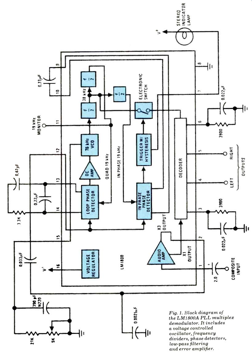
Fig. 1. Block diagram of the LM1800A PLL multiplex demodulator. It includes
a voltage controlled oscillator, frequency dividers, phase detectors, low-pass
filtering and error amplifier.
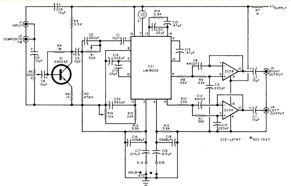
Fig. 2. Schematic of the multiplex detector. Transistor Q1 amplifies the
input to drive the PLL. Operational amplifiers IC2A and IC2B form active
low-pass filters.
PARTS LIST
C1, C3 through C7, C11-10-µF, 25-volt tantalum capacitors
C2,C9,C12--220-pF disc ceramic or silver mica capacitor
C8,C10---440 pF disc ceramic or silver mica capacitor (can be two 220-pF capacitors in parallel)
C13--0.05-µF disc ceramic capacitor
C14--0.002-µF disc ceramic capacitor
C15, C21--0.47-µF Mylar capacitor
C16,C18--0.0068-µF, 110%p Mylar capacitor
C 17,C 19--0.015-µF, ± 10% Mylar capacitor
C20--0.22-µF Mylar capacitor
C22--330-pF disc ceramic or silver mica capacitor
I1--12-V, 35-mA pilot light
IC1-LMI800A PLL multiplex decoder
IC2-747 dual operational amplifier
JI through J4-RCA phono jacks
Q1-2N5232 npn silicon transistor
The following are linear-taper, pc trimmer potentiometers: R1-50,000 ohms R5-200,000 ohms R 16-10,000 ohms
The following are 10% tolerance, 1/4-watt carbon-composition fixed resistors: R2-470,000 ohms R3, R14-3300 ohms
R4--1 Megohm
R6-1000 ohms
R7-See text.
R8 through R 11--33,000 ohms
R12, R13--3900 ohms
R15--22,000 ohms
S1--Dpdt slide or toggle switch
Misc.-Printed circuit board, suitable enclosure, hookup wire, shielded cable, pilot light jewel, hardware, solder, etc.
Note--The following are available from Netronics Research and Development, Ltd., 333 Hitchfield Road, New Milford, CT 06776: complete kit including all components, pc board, screened enclosure, less audio cables, $24.95; complete kit as above but less screened enclosure, $19.95. U.S. residents add $1.50 postage and handling; Canadians add $3.00. For receiver connection info, send schematic, SAS envelope and $1 (free if purchasing kit). Connecticut residents add 7% sales tax.
The schematic diagram of the complete multiplex detector is shown in Fig. 2. Input signals are capacitively coupled by C5 to level control R5. Capacitor C4 passes the composite FM input to the base of Q1, which amplifies it to a level that will properly drive the phase-locked loop. The parallel combination C2R1 provides compensation for high-frequency rolloff in the tuner's i-f and detector stages. Resistors R12 and R13 and capacitors C16 through C19 provide deemphasis for multiplex decoder IC1. When S1 is in the sro position, the standard 75-µs FM deemphasis characteristic appears. Placing S1 in the DOLBY position changes the de-emphasis to 25 µs, which corresponds to the reduced preemphasis used in Dolby-encoded broadcasts.
Operational amplifiers IC2A, IC2B, and their associated components form active low-pass filters with 16,000-Hz cutoff frequencies and 12-dB/octave slopes. These filters attenuate any 38-kHz carrier and 67-kHz SCA components which would otherwise appear at the left and right audio outputs. If allowed to pass, these signals could cause beats and whistles when program material is recorded on tape. Indicator I1 glows in the presence of stereo pilot carrier. Jack J2 is wired in parallel with input jack J1, providing access to the composite FM signal for such accessories as 4-channel and SCA demodulators.
Construction. Printed circuit guides for the project are shown in Fig. 3.
Mount all components on the board, paying close attention to pin basing and polarities of semiconductors and electrolytic capacitors. Power can be tapped from any +12 to +24-volt dc source.
The tuner's i-f stage or existing multiplex decoder is usually powered by a +15 to +20-volt supply which can be utilized for this purpose. Select the value of R7 in kilohms according to the equation: R7 = (V supply-12) / 55 A one-watt carbon composition resistor will have adequate heat dissipation capability for this application.
==========
TABLE:
Stereo Separation--100 Hz: 40 dB' 1000 Hz: 45 dB 10,000 Hz: 45 dB
SCA Rejection: 50 dB
Total Harmonic Distortion: 0.2 %
Ultrasonic Frequency Rejection: 45 d8
===========
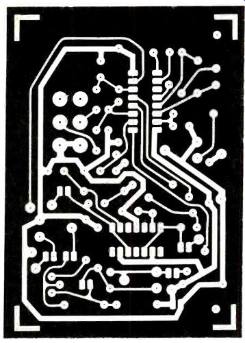
Fig. 3. Etching and drilling guide for multiplex decoder is shown at
left. Component placement guide is above.
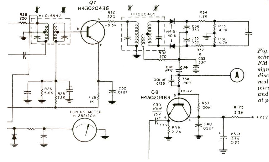
Fig. 4. Partial schematic of typical FM receiver. Composite signal is obtained
by disconnecting existing multiplex decoder (circuit below C34) and tapping
signal at point A.
The tuning lamp used in the author's prototype (and supplied with the kit) draws 35 mA at 12 volts. If you substitute another incandescent lamp or a LED and current limiting resistor, modify the equation for the value of R7. Replace the 55 mA in the denominator with the sum of 20 mA (the current required by the PLL and active filters) and the current required by the indicator. For example, if a LED and resistor drawing 20 mA are used, the denominator would be 40 mA. The project can be mounted in the tuner cabinet or housed in a separate enclosure. If it is placed in the tuner cabinet, mount S1 on the rear panel of the tuner and connect it to the pc board via low-capacitance shielded cable such as RG-59-U. The same type of cable should also be used to conduct the composite FM signal from the detector output to the input of the multiplex decoder.
If your tuner or receiver has a "composite FM" or "FM detector" output jack, the required signal is available there. If not, you will have to locate the FM detector and tap the signal at that point.
The partial schematic of a typical FM receiver is shown in Fig. 4. The composite signal is obtained by disconnecting the existing multiplex decoder and tapping the signal at point A. The left and right audio outputs are available at jacks J3 and J4. If you are using the project in place of the multiplex decoder in a tuner, you can either use these jacks place assuming the decoder is mounted externally. If it is mounted internally, you can disconnect the outputs of the existing multiplex decoder from the output jacks on the tuner's rear panel and connect the outputs of the decoder's active filters.
Similarly, if you have a receiver and are mounting the project in an external enclosure, you can connect the decoder's outputs to the tape monitor circuit.
Mounting the decoder inside the receiver cabinet suggests an internal connection. Remove the output leads at the existing multiplex decoder running to the appropriate lugs on the receiver's MODE switch. Then connect them to the decoder's active filter outputs.
Alignment. When properly aligned, the project will provide performance as outlined in Table I-assuming no degradation in the tuner's i-f and FM detector.
Two typical receivers were used with the PLL decoder. Results are shown in Table II. The alignment procedure about to be described requires no test instruments, but will yield good results. The author was able to improve the stereo separation only 2 dB when instrument alignment was performed with an expensive FM stereo generator.
Rotate potentiometers R1 and R16 to the midpoint of wiper travel, and R5 for maximum signal drive at the base of Ql.
Turn on your receiver and tune in a station broadcasting in stereo. Indicator /1 should glow. If not, adjust R16 until it does. Then turn R16 fully clockwise. If 11 still glows, adjust R5 until the indicator just goes out. Slowly rotate R16 counter-clockwise until the lamp begins to glow.
Note the position of the control. (It may be necessary to adjust R5 slightly.) Next, turn R16 fully counterclockwise, adjusting R5 again if necessary to extinguish the lamp. Slowly rotate R16 clockwise until the lamp glows, noting the position of the control. Set R16 midway between the two positions noted. Adjust R5 until the lamp goes dark, then slowly turn it until the lamp just starts to glow.
Advance the wiper of R5 another 10°. This will properly tailor the input level to decoder ICI. Potentiometer R1 is included in the circuit for adjustment if test equipment or a cooperative FM broadcast engineer is available. Since all stations must conduct tests and certify the quality of their signals once a year, you can easily check out adjustments. Call several local stations and ask when they will perform the tests. If it is late at night, the engineer might turn off a channel for 30 seconds or so. While only one channel is being transmitted, adjust R1 for maximum separation at any mid-band frequency. Note, however, the setting of R1 will not have a critical effect on the performance of the decoder and can simply be left midway between the two adjustment extremes.
TABLE II--RECEIVER MODIFICATION RESULTS
[ P-E Exp. 1980a]
Also see:
Link | --Link | --Build the Audio Detective
Build A State-Of-The-Art Battery Charge Monitor