BY BARTON M. BRESNIK
Lets you know when a power outage occurs.
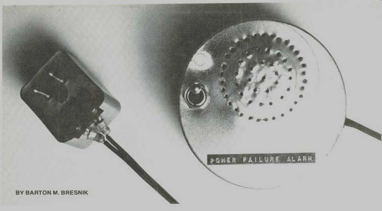
SUMMER or winter, night or day, a power outage in your local utility system can cause all sorts of problems in your home. Heating and cooling systems shut down, refrigerators and freezers come to a halt, and your electric alarm clock stops running, making you late for work.
The power-failure alarm is a battery-powered device that sounds an alarm when a power failure occurs. Then you can, at least, turn off devices that might blow fuses when the power returns and take what other steps are necessary to protect your property.
How It Works. Battery B1 (Fig. 1) gets a constant trickle charge from the transformer through D1 and R1. As shown here, the battery is made up of two 1.25-V NiCd cells. Sealed NiCd or lead-acid storage cells with higher voltage ratings could be used. Vented secondary batteries can be used if the electrolyte is checked every few months. If carbon-zinc or manganese-alkaline cells are used, the value of R1 should be increased to 47,000 ohms. Remember also that manganese-alkaline and mercury cells may burst when recharged.
The alarm generator consists of a two-transistor astable multivibrator and associated loudspeaker, while the trigger portion uses an SCR and related bias components. The SCR is in a feedback 'cop from the emitter of 02. The gate of SCR1 is biased low enough to keep it from firing as a result of the combination of R3 and R4. When a power outage occurs, the voltage from the battery turns on the SCR, and the multivibrator provides an audio-frequency signal to the speaker.
The time delay provided by C1 and R3 is used to keep the system from operating in case there is only a brief loss of power (which can be caused by lightning) or a line transient.
In standby operation, the circuit draws less than 1 mA, which is supplied by the trickle charging current. When an outage occurs, and the SCR turns on, the current increases to 15 mA for a 2.5-V battery and 50 mA for a 4.5-V source.
The lamp circuit is optional and can be used to check the battery. The lamp can also be made to glow during a power outage by connecting a silicon diode between the LAMP position of S1 (anode of the diode) and the anode of SCR1 (cathode of the diode).
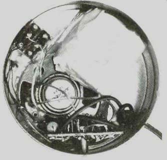
------------ Author's prototype was assembled in a 35-mm film container.
PARTS LIST
B1--Two 1.25-V NiCd cells ( Lafayette 32F47400 or similar)
C1--100-µF, 10-V electrolytic capacitor
C2--0.05-µF disc capacitor
D1, D2--1N4001 diode -2.5-to-3.0-V lamp (or #48)
Q1--2N3638 transistor
Q2--General-purpose npn transistor
R1--680-ohm, 1/4-W 10% resistor (or 47,000-ohm, see text)
R2--3300-ohm, 1/4-W 10% resistor
R3,R4,R5--10,000-ohm, 1/4-W 10% resistor
R6--1000-ohm, 1/4-W 10% resistor
R7-100-ohm, 1/4-W 10% resistor
SCR1-Silicon controlled rectifier (GE-X5 or 2N5060)
SPKR--8- or 10-ohm speaker (Lafayette 99F60972 or similar)
S1--Spdt switch
T1--6.3 volt, low-current "wall-socket" transformer ( Lafayette 33F37029 or similar)
Misc.-Suitable enclosure, rubber grommet, mounting hardware, circuit board, etc.
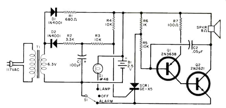
Fig. 1. The two-transistor audio oscillator is inoperable until the SCR
conducts. This occurs when the power line fails and the battery voltage is
applied to the SCR gate. Do not use an on-off switch with the unit.
Construction. The prototype of the alarm was assembled on a small piece of perforated board with point-to-point wiring. For transformer TI, use a standard recharging unit which plugs directly into a wall socket. This provides a safety feature in that only 6.3 volts is used in the chassis.
Mount the completed assembly in any type of enclosure with only S1 and some speaker holes on the top. (The author used a 100-ft, 35-mm film container.) The optional "grain-of-wheat" lamp can be mounted in a hole drilled in the container, using epoxy glue to secure it in place. Since none of the parts listed is critical, feel free to experiment with "junk box" items.
To test the device, turn the switch to OFF, plug the transformer in a power outlet, and then turn the switch to ALARM. Unplug the transformer from the wall socket. After a few seconds, the alarm should sound, continuing even when the transformer is put back in the socket.
This locking feature reminds you to reset clocks if you were not at home when the outage occurred.
If you are using rechargeable cells, connect a current meter in series with the battery and check that, with the transformer plugged in, the charging current is within the limits prescribed for the cell.
[ P-E Exp. 1980a]
Also see:
Link | --Link | --Build the Audio Detective
IC Multiplex Decoder Improves FM Performance