Battery-operated device gives accurate readings up to 50,000 rpm without physical contact.
BY ADOLPH A. MANGIERI
IF you service the numerous motor-driven' appliances and tools found in the home, shop, or factory, consider building this photo tachometer. By recording normal rotational speeds for comparison with later measurements, you can easily detect the effect of worn gear trains or motor brushes and gauge improvement of performance after repairs. With no mechanical coupling required, the Photo-Tach measures the rpm of any type of rotating element, including miniature high-speed, low-power motors. You can also use the Photo-Tach as an analog frequency meter, useful for checking inverters and auxiliary ac generators.
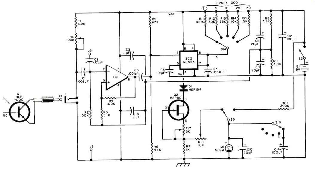
Operated in either the incident or reflected light mode, the Photo-Tach includes five ranges up to 50,000 rpm. A plug-in light probe, using a high-speed photo-transistor, facilitates speed measurements. Using low-cost, high-performance IC's, the battery-operated tachometer features high accuracy and stability. See schematics in Fig. 1.
How It Works. Light pulses striking photo-transistor Q1 produce voltage pulses at the input of operational amplifier IC1, connected as a Schmitt trigger which produces a sharply squared output pulse for each input pulse. Resistors R3 and R4 provide positive feedback and also determine the input voltage hysteresis or deadband. This prevents the tach from responding to noise components of the main signal and rejects the small 120-Hz modulation of 60-Hz incandescent light sources. Input highpass filter, C1-R2, favors response to fast-changing light signals.
Output pulses from IC1 are differentiated by C6-R6 forming voltage spikes which are applied to the trigger input terminal (2) of timer IC2, connected as a monostable. When a negative-going trigger pulse drives pin 2 below one-third Vcc, the timer delivers a precise output pulse Vo at pin 3. Output pulse duration, independent of supply voltage, depends on timing capacitor C7 and a timing resistor selected by range switch S1. Output pulses Vo pass through diode D1 and energize FET constant-current source Q2-R17, producing constant-amplitude pulses across R7. Diode Dl blocks the small residual voltage when Vo is low. Constant-duration pulses of constant amplitude are averaged by meter Ml which responds linearly to the repetition rate of input light pulses.
Potentiometer R16 adjusts the input sensitivity while capacitor C11 dampens meter pointer vibration at low (2500) rpm. With a pulse duty cycle of near one-third at full scale, meter overrange is within safe limits.
Construction. Assemble the photo-Tech in a 3" x 4 1/2" x 6 1/2" metal case. In the prototype, perf board construction was used but you can make a printed circuit board using the foil pattern shown in Fig. 2. Use sockets for IC1, IC2, and Q2, and use short, heavy buses on the circuit board as common tie points to avoid ground loops. Install bypass capacitors C3 and C4 close to their IC1 pins.
Wire R16 so that its resistance is zero with the control set counterclockwise.
Voltage-range multiplier resistor R10 is, preferably, 1% tolerance.
==============
PARTS LIST
B1--9-volt battery (Burgess 2U6 or equiv.) C I-0.002-µF 10% ceramic disc capacitor C2-0.05-µF ceramic disc capacitor C3,C4-0.l-µF ceramic disc capacitor C5-0.01-µF ceramic disc capacitor C6-0.001-µF 10%< ceramic disc capacitor C7-0.068-µF 10% Mylar capacitor C8,C9,C10-20-µF 15-V electrolytic capacitor C11,C12--100-µF, 15-V electrolytic capacitor D1-Silicon diode (HEP 154 or equiv.) ICI-Operational amplifier (HEP C6052P or 741C) IC2-555 timer IC J I-Miniature phone jack 12, J3-Phone tip jack (one red, one black)
M1-11-50-microampere dc meter PI-Miniature phone plug Q1-Photo transistor (HEP P0001, HEP 312, or equiv.) Q2-N-channel JFET (HEP 801 or equiv.). R 1 ,R8,R9-3900-ohrh, 1/2-watt 5% resistor R2-150,000-ohm, 1/2-watt 10% resistor R3-5100-ohm, 1/2-watt 10% resistor R4-100,000-ohm, 1/2-watt 10% resistor R5,R6 47,000-ohm, 1/2-watt 5% resistor R7-1000-ohm, 1/2-watt 5% resistor R10-200,000-ohm, 1/2-watt 1 % resistor R 1 1-100,000-ohm resistor R 12-50,000-ohm resistor R13-25,000-ohm resistor 5% or better R 14-10,000-ohm resistor R 15-5000-ohm resistor R16-100,000-ohm audio taper potentiometer, with spst switch S2. (Radio Shack 271-1727 or equiv.) R17-5000-ohm trimmer (Radio Shack 271-217)
R18-10,000-ohm trimmer (Radio Shack 271-218)
S1--Dp, 5-pos. shorting switch (Centralab PA-1002 or equiv.) S2-Spst switch (on R16)
S3-Sp, 2-circuit momentary pushbutton switch
Misc.:-Transistor socket: DIP sockets (2); metal case 4 1/2" x 61" x 3" (Vector W30-66-46B or equiv.); P-pattern perforated board; knobs (2); battery clip; miniature shielded cable; flea clips (Vector T42-1 or equiv.) hardware; etc.
==============
Fig. 1. The light pulses at Q1 are squared up in IC1 and turn on precision
monostable 1C2. Constant-current output pulses through Q2 are averaged
by the meter as rpm. Five ranges permit testing up to 50,000 rpm.
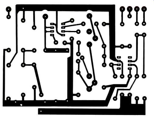
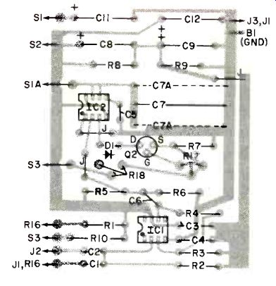
Fig. 2. Though the prototype of the tachometer Joas atisembled on perforated
hoard, it is convenient to 14 tie (1 priutcd circuit board. C7A is
two 0.033 capacitors if this is preferred to one 0.068.
Connect the supply minus to case (ground). Tape over any unused pins of the IC sockets and carefully observe correct installation of the IC's. Remove the meter dial card and mark the additional scales using dry transfers (see photograph). Otherwise, mark rpm range switch S1 with multipliers of the 0-50 scale. Do not connect a meter protector across M1.
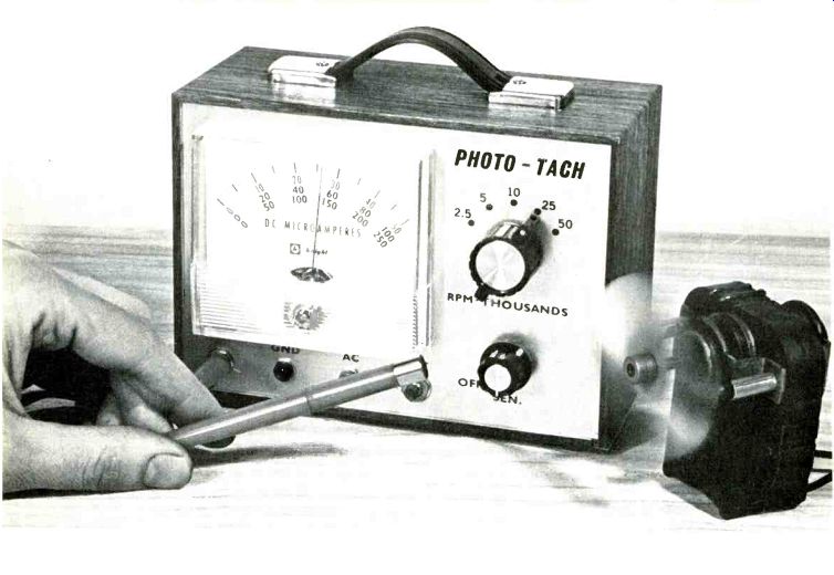
Mount the meter, range switch Si, sensitivity control R16, battery test switch S3, probe input jack J1, ac input connector J2, and the ground connector J3 on the front panel as shown in the photographs.
For photo-transistor Q1, use either a glass lens (HEP P0001) or plastic lens (HEP 312). Clip off or insulate the unused base lead of the P0001 transistor.
Connect the outer braid of a three- to four-foot length of miniature shielded cable to the emitter of Q1 and center conductor to collector. Make sure the braid is connected to the grounding side of the P1-J1 combination. Install Q1 within an opaque plastic tube, such as the barrel of a ballpoint pen. Position the lens about one-quarter inch from the tip of the probe. Install battery B1 on the back plate of the cabinet.
Calibration and Checkout. Set R17 and R18 to mid-position and S1 to 2500 rpm, then connect a dc voltmeter across R7. This test voltmeter input resistance should be at least 50,000 ohms on the selected voltage range. Disconnect wire "X" from the rotor of switch S1A. Operate sensitivity control R16 to close S2. If M1 is not pegged upscale, short R6 momentarily, causing Vo to go high. Adjust R17 until the voltmeter indicates one volt. Remove the voltmeter, open S2, and reconnect wire "X" to SIA. Breadboard the calibration circuit shown in Fig. 3, which supplies a 120-Hz signal (equivalent to 7200 rpm) and connect to jacks J2 and J3. Set S1 to 10,000 rpm, close S2 and adjust R18 until M1 indicates 7200 rpm. With accurate range resistors, all ranges are simultaneously calibrated to high accuracy. You can use a signal generator to calibrate, check, or trim rpm ranges provided frequencies can be set to high accuracy, as with a frequency counter.
Multiply frequency by sixty to obtain equivalent rpm.
Next, check rejection of the small 120-Hz modulation of incandescent light sources. Insert the probe in J1 and aim the probe at a 50or 75-watt lamp at distances of two inches to three feet while varying R16 (sensitivity control) over its range. If M1 does not remain at zero under all conditions, increase input hysteresis by increasing R3 to 8200 or 12,000 ohms. If further remedy is required (not likely), reduce R2 to 100,000 or 82,000 ohms and/or reduce C1 to 0.001 µF. Connect a 1500-ohm potentiometer (set for minimum resistance) in series with the plus lead of B1. Connect the calibrating signal to J2 and J3. Increase the potentiometer resistance until M1 drops to 7100 rpm or about 1% lower.
Depress pushbutton switch S3 and observe battery end-point voltage on M1, read as 0-10 volts dc. End-point voltage should be near 6.6 volts or less. If the voltage is above 7 volts, use a 12-volt battery for B1 (made up of eight AA cells connected in series). The additional supply voltage accommodates a FET (02) having a pinch-off voltage above 3 volts.
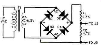
Fig. 3. Calibration circuit delivers a 120-Hz signal equivalent to 7200
rpm. Multiply frequency by GO to obtain the equivalent speed.
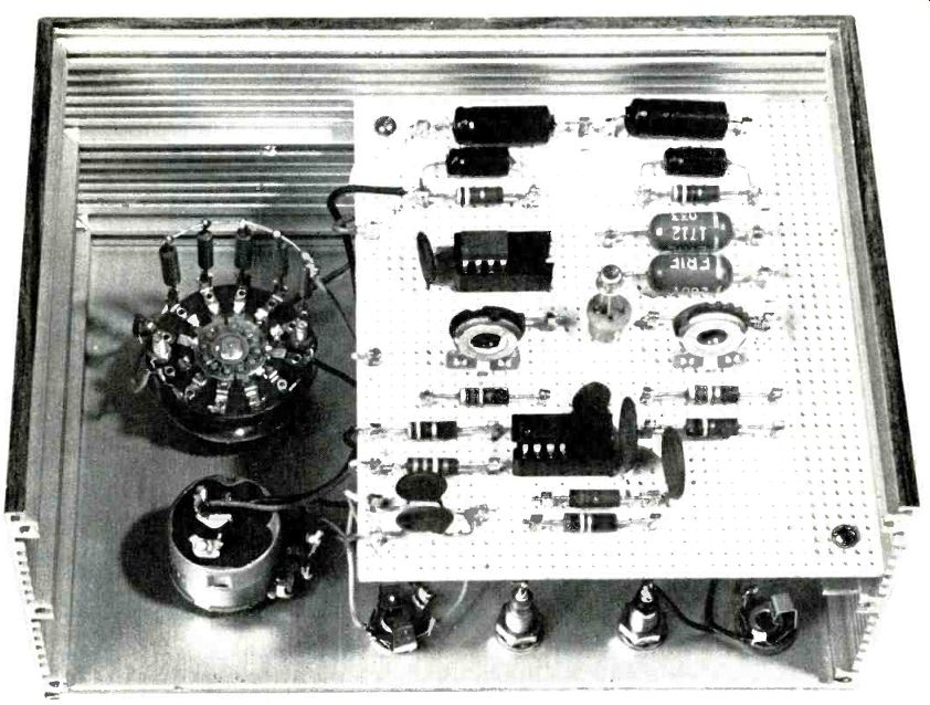
-------- Photograph of prototype, assembled using a perforated board,
shows how parts were assembled in chassis. The arrangement of the front
panel is shown in the title photo.
Applications. In the incident-light mode of operation, the rotating element whose rpm is to be checked chops or gates the light traveling directly from a light source to the probe. This provides a noise-free, large-signal input to the tach.
A reflectorized handy light with a 50- to 100-watt lamp proved a most convenient light source but you can use a desk lamp, drop cord, or a flashlight.
Position the light source about two feet behind the blades of an operating electric fan. Hold the probe near the front of the fan, aimed at the lamp.
Advance R16 until M1 shows a steady and maximum indication. Observe that R16 can be varied over much of its range while M1 remains steady. For a fan with four blades, divide indicated rpm by four, etc.
To check the speed of a drill, construct a light chopper using a three-inch diameter cardboard disc. Cut out 3/4" x 3/4" light gate at the edge and chuck the disc in the drill using a machine screw.
To check motors having various shaft sizes, attach a light chopper disc to a suitable wheel, shaft collar, or knob. The spokes of a large pulley can serve as a light chopper.
In the reflected-light mode, the sensor views light reflected from contrasting surfaces. If surface reflectivity is excessively uneven due to rust spots, discolorations, or other irregularities, a reflected-light pulse may contain excessive noise. This will be recognized as a very high and erratic indication on the meter. Involving two directions of light travel, the reflected-light mode may require rigging of probe or light source, or both, to maintain steady indications.
To check the speed of a motor having a half-inch shaft or larger, wrap a strip of electrician's tape (cloth friction type, not glossy surface vinyl) around the shaft.
Place the band on a shaft flat if possible.
Place a strip of white surgical adhesive tape lengthwise across the band. Or, paint a white strip using fast-dry flat paint. Rig the probe horizontally about one inch from the shaft facing the band.
For the flatted shaft with white strip on the flat, hold the light source directly above the shaft at a distance of about 8 to 12 inches. For the round shaft, hold the lamp about 6 inches above the end of the probe handle. Advance R16 and verify that the meter indication remains steady over some portion of pot rotation, proving adequate light input. For motors having smaller shafts, attach a reflective disc to a suitable wheel or knob. Paint half of the disc flat black and the balance flat white. Fan speed can be checked by this method provided the fan blades are clean and uniform in appearance. By sighting the running fan from several angles, you can pick a suitable direction to aim the probe. Particularly with very small fans, a slightly twisted blade can result in a missed light pulse.
Meter-pointer vibration becomes apparent below 400 rpm. In this case, include a second light gate or reflective surface and divide indicated rpm by two, etc. Position additional light gates or reflective surfaces in an approximately symmetrical pattern.
Keep tabs on the normal running speeds of appliances and tools for later comparisons. Use speed measurements to isolate problems between motor and drive train and observe effect of repairs. Speed measurements on major heavy-duty appliances such as washers and dryers can forewarn you of progressive wear which may lead to motor overload and possible fire hazards.
The tachometer can be used as a low-range frequency meter to check frequencies from about 10 to 800 Hz. Inject one or two volts ac into jacks J2 and J3 and divide indicated rpm by 60. Also, by connecting J2 and J3 to a scope, you can observe input to the tach as you vary lighting and sensitivity settings.
Also see:
Link | --Link | --Power-Failure Alarm