BY COLLEEN McNEICE AND ROGER COTA
Hand-held LED display instrument is said to detect voice stress

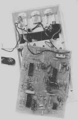
------LEDs are positioned in window area, miniature microphone is
put in center cutout al top of case.
SO-CALLED "electronic lie detectors" have become controversial items Some workers in the fields of security and law-enforcement swear by them, while others (inducing some psychologists) hold that the principles on which the devices are based are ill founded and unscientific. Still other individuals denounce the application of lie detectors as an invasion of privacy.
Actually. the best that these detectors can do is measure psychological stress. Even then, the measurement is indirect. Basically, the device makes its determination by sensing an effect of one type or another that many researchers believe is an accurate indicator of stress. Validation studies have been used to compile an impressive record of successes, but it should be remembered that a high degree of interpretational skill is required and there is always an appreciable probability for error in using such an instrument.
One popular indicator of stress has been the relative amplitude of certain vocal modulations in a person's speech.
The Voice Stress Analyzer described here is a small, readily portable unit. It is designed to operate on the principles pioneered by Dektor and other companies in the field whose products have received wide acceptance.
Basic Theory. Extensive military re search and wartime counterintelligence work have yielded several theories and devices that have been used during interrogation in an attempt to separate truth from falsehood. One of these theories is that human voices, which have fundamental frequencies ranging from about 90 to 200 Hz, are normally modulated by an 8-to-12-Hz "micro-tremor" signal. The latter's effect is usually masked by other voice components: but, according to these researchers, reason ably simple electronic circuitry can detect and measure the microtremors.
When a person is under stress, says the theory, normal vocal microtremors diminish greatly in amplitude. The autonomic nervous system, preparing the body for emergency reactions, causes the pupils to dilate, blood to rush away from the limbs, and the muscles to tense. Since the vocal chords are principally muscular tissue, they, too, tighten and decrease the amplitude of microtremors. Thus, it is claimed, measuring the relative amplitude of vocal microtremors gives an indication of stress. The wave form of a human voice with microtremor, indicating no or very little stress, is shown in Fig. 1A, its spectral content in Fig. 1B.
System Operation. Basic operation of the Voice Stress Analyzer is shown in Fig. 2, while Fig. 3 illustrates typical waveforms (not drawn to scale) that occur in the circuit.
The input voice signal in Fig. 3A illustrates the somewhat closer peak spacing attributed to microtremors as com pared with the "normal" spacing of the peaks in the voice signal. After amplification, the composite voice signal goes to a voice-frequency bandpass filter to remove extraneous noise. Then the signal input is half-wave rectified. In a 150-Hz low-pass filter, the higher voice frequencies are attenuated, leaving only the lower frequencies, including those of the microtremors (Fig. 3B). The positive-going output then toggles a Schmitt trigger (Fig. 3C) to produce a squared-off waveform. The latter is suitable for toggling a one-shot multivibrator that then produces the 1.5-ms pulses shown in Fig. 3D.
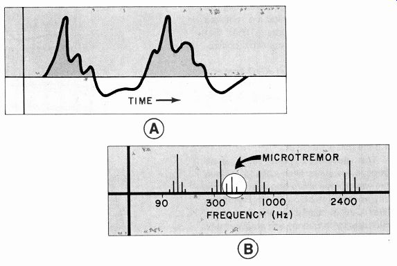
Fig. 1. Waveform of the human voice with microtremors is shown at
(A), spectral content of voice is at (B).
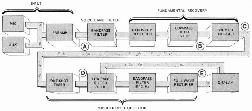
Fig. 2. The analyzer circuit is designed to extract the 8-to-12-Hz
microtremor from the voice input and use the resultant signal to turn
on a LED display.
As the 8-to-12-Hz microtremor modulates the fundamental, spacing between pulses changes. Pulses from the one shot then pass through a 20-Hz low pass filter and an 8-to-12-Hz filter, after which it is rectified and integrated to form a smooth voltage. This signal may rise above a preset threshold when the microtremors are closely spaced, in a manner similar to that of the vertical-sync scheme used in a TV receiver.
When the integrated output is above the threshold, it causes the LEDs to come on in a particular sequence (Fig. 3E).
The Circuit. Figures 4 and 5 illustrate the complete schematic diagram of the Voice Stress Analyzer. The IC2D circuit (Fig. 5) supplies the ground tap required by the op amps. Resistors R1 and R2 and capacitor C1 provide power from battery 81 for the condenser micro phone. Jack J1 is a transfer type that disconnects M/C when an external audio source is plugged into it. (The external source can be a telephone pickup, dynamic microphone, or output from a tape recorder.) Audio amplifier 1C1A operates close to its open-loop gain whose output goes to the /C1B bandpass-filter circuit. Rectifier D1 half-wave rectifies the signal to recover the fundamental modulating frequency. Higher harmonics are removed by IC 1C, an 18-dB / octave filter that passes only those frequency components below 150 Hz.
Schmitt-trigger circuit IC 10 converts the recovered fundamental into steep rising and falling edges that are suitable for driving timer IC4. As shown in Fig. 3C and D, the Schmitt trigger's sharp rise time toggles the timer, which produces a 1.5-ms pulse.
The generated pulse train goes through low-pass filter IC2A to remove the waveform's sharp edges and amplify any frequencies below 20 Hz. Bandpass filter IC2B is "tuned" to the 8-to-12-Hz microtremor frequency and amplifies any signal within this range.
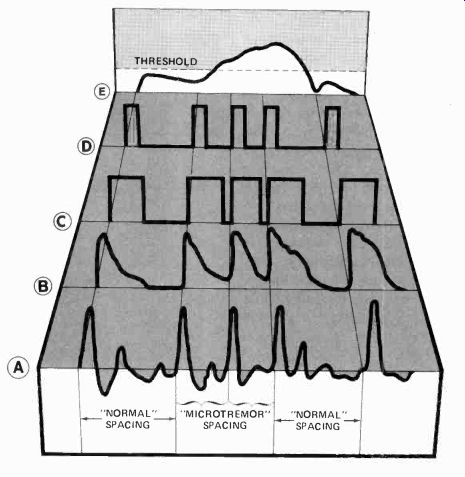
Fig. 3. Typical waveforms within the analyzer. According to the authors,
the "trick" lies in detecting the presence of the narrower
microtremor peak spacing within the voice frequencies. Integrated one-shot
pulses derived from these signals are used to toggle the readouts.
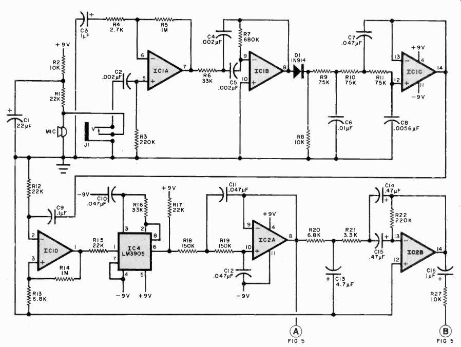
Fig. 4. The voice processing circuits of the analyzer result in 20-Hz
signals from IC2A and 8-to-12-Hz signals from IC2B. These signals drive
the rectifier/display section shown in Fig. 5.
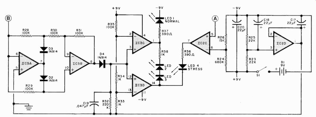
Fig. 5—The 8- to-12-Hz signals are rectified 1 in IC.1.1 and IC3B,
integrated in 1'1.9 and used to (nil) on a comparator IC3C that causes
the LED (s) to glow. IC2C shuts down the LEDs when there is no 20-hz
signal, while IC2D creates a bipolar supply from a single 9-eolt battery.
Full-wave rectifier IC3A I IC3B accepts this signal and produces a dc out put voltage that is proportional to the amplitude of the microtremor (Fig. 3E).
This voltage is developed across C19, which is constantly being discharged by time-constant resistor R32.
Display drivers IC3C and IC3D are connected as comparators, using the voltage generated across R33, R34, and R35 as the reference. The comparators then drive the LEDs. When LED1 comes on, presence of microtremors is indicated, meaning no stress. When these frequencies are missing, LED4 comes on to indicate high stress. As microtremors come and go, LED2 and LED3 come on.
The display also receives a control signal from the 20-Hz filter that turns off the LEDs when no input signal is present, conserving battery life.
Construction. Using the actual-size etching and drilling guide shown in Fig. 6, the Analyzer was designed to fit in a calculator-type case. Referring to the component-placement guide in Fig. 6, mount the components in their respective locations, taking care to properly orient the diodes, polarized capacitors, ICs, and LEDs. When installing components on pc board, be sure to properly orient diodes, LEDs, ICs, and electrolytic capacitors, as shown in the component placement guide.
-----------
PARTS LIST
B1-9-volt battery C I ,C17.0 I 8,C20-22-µF, 16-volt tantalum C2,C4.C5---0.002-µF, 100-volt Mylar C3,C16-1-µF, 100-volt electrolytic C6-0.01-µF, 100-volt Mylar C7,C10,CI I ,C12,C19--0.047-µF, 100-volt Mylar C8-0.0056-µF, 100-volt Mylar C9-0.1-p.F, 100-volt Mylar CI3 35-volt tantalum C14,C15 0.47-µF, 35-volt, tantalum D1 through D4-1'181914 ICLIC2,1C3-LM324 quad op amp 1C4-LM3905 precision timer J I-subminiature phone jack with switch LEM through LED4--red LED The following are 1/4-watt 57 resistors:
R I .R12,R15,R17,R23,R25 22,000 ohms R2,R8,R27- 10,000 ohms R3,R22,R32-220,000 ohms R4 2700 ohms R5,R14 I megohm R6,R16-33,000 ohms R7,R24 680,000 ohms R9,R I 0,R11-75,000 ohms RI3,R20-- 6800 ohms R 18,R 19-150.000 ohms R21---3300 ohms R26-- 15,000 ohms R28 through R3I,R35-100,000 ohms R33,R34,R38-1000 ohms R36,R37-390 ohms Misc. suitable enclosure, battery clip, hook up wire, mounting hardware, etc.
Note: The following is available from Video Control. 3314 11 St.. Vancouver. WA 98663 (Tel: 206-694-7905): complete kit including microphone, battery clip. pc board. case, and manual for $96.00. Also available separately: etched and drilled pc board at 512.50, hand-held case. battery clip with power jack and condenser microphone at $18.00. Please add $3.50.16r postage/handling. ' Washington state residents, please add 5.1% sales tax. Allow 4 weeks for delivery.
-----------
With exception of the microphone, auxiliary input jack, power switch, and battery, all components mount directly on the circuit board. The microphone and auxiliary jacks mount in holes at the top of the plastic case. (Make certain that the pickup end of the microphone points outward.) Mount the power switch on the upper surface of the case, below the display window and label its ON position with a dry-transfer lettering kit. Connect and solder the positive lead of 81's battery connector to the hole A-pad on the circuit board, the negative lead to the hole B-pad.
Examine the jack and schematic diagram and connect and solder lengths of hookup wire from the jack's lugs to the appropriate E, F, and G pads on the circuit board. If you choose a rechargeable battery for B1, mount a suitable power jack on the plastic case and wire it to the battery.
Now, use a dry-transfer lettering kit to label the LEDs in the display. Label LED1 NORMAL and LED4 STRESS. Leave transitional LED2 and LED3 without legends. This completes construction.
Construction. Using the actual-size controls, it should be operational as soon as power is turned on. As you speak into the microphone, you should note that the LEDs flicker, with the NOR MAL LED on most of the time.
A number of tests were performed on the Voice Stress Analyzer by one of the authors. Using the audio from a TV-network news broadcast, it was noted that when the newscaster spoke, the NORMAL LED was on most of the time.
When actors and actresses were speaking their roles, basically the same results were observed. However, when active filter the filter will not appreciably load any circuit to which it is connected. The audio output can feed loads as low as 300 ohms without degrading the filter performance. (Most hi-fi phones have lower impedances and will not work.) Construction. Although a pc board is not a necessity, an actual-size foil pattern and component installation i shown in Fig. 2. If desired, the circuit can be created using Wire-Wrap or any other assembly technique.
Since the circuit requires only 1.2 mA when operating, a conventional 9-volt battery will have a reasonably long life If the receiver being used for code reception has a power supply between 5 and 30 volts, this voltage can be used to power the filter. Keep in mind, that if more than 20 volts or so is used, the rating o C6 will have to be increased accordingly. Maximum supply voltage for the op amps is 30 V. An optional power switch may be used to remove the volt age from the filter when not in use.
The filter can be mounted within the receiver case or in a small outboard en closure. Audio input can be taken from the earphone jack, if provided with the receiver, from the loudspeaker connections, or from a low-level audio circuit.
W1AW CODE PRACTICE SESSIONS EST PST
Speeds: 5, 712, 10, 13, and 15 wpm Mon. 9 a.m., 7 p.m.
Tues. 4 p.m , 10 p.m.
Wed. 9 a.m., 7 p.m.
Thur. 4 p.m., 10 p.m.
Fri. 9 a.m., 7 p.m.
Sat. 4 p.m., 10 p.m.
Sun. 4 p.m. 10 p.m.
6 a.m., 4 p.m.
1 p.m., 7 p.m.
6 a.m., 4 p.m.
1 p.m., 7 p.m.
6 a.m., 4 p.m.
1 p.m., 7 p.m.
1 p.m., 7 p.m.
Speeds: 10, 13, 15, 20, 25, 30, and 35 wpm
Mon. 4 p.m., 10 p.m. 1 p.m., 7 p.m.
Tues. 9 a.m., 7 p.m. 6 a.m., 4 p.m.
Wed. 4 p.m., 10 p.m. 1 p.m., 7 p.m.
Thur. 9 a.m., 7 p.m. 6 a.m., 4 p.m.
Fri. 4 p.m., 10 p.m. 1 p.m., 7 p.m.
Sat. 7 p.m. 4 p.m.
Sun. 7 p.m. 4 p.m.
Frequencies: 1.835, 3.58, 7.08, 14.08, 21.08, 28.08, 50.08, 147.555 MHz.
Use. With the filter connected to the receiver audio, and a suitable amplifier or headphones connected to the filter output, tune in the desired CW trans mission, and note the very sharp "peak" that occurs with filter use. It becomes very easy to "fine tune" the receiver, or its bfo, to produce a clean CW signal at the filter output. A dramatic falloff of interfering signals indicates that the filter is working properly.
Source: (Popular Electronics Electronic Experimenter's Handbook (1983)
Also see:
An Experimenter's Guide to Relay Control
Tools & Equipment for Electronic Workbenches