Analog signals can be conveyed from one device to another with relative ease, but the transfer of audio signals in the digital domain is a good deal more complex.
Sampling frequency, word length, control and synchronization words, and coding must all be precisely defined to permit successful interfacing. Above all, the data format itself takes precedence over the physical medium or interconnection it happens to currently occupy. Numerous data formats have been devised to connect digital audio devices, both between equipment of the same manufacturer, and between equipment of different manufacturers. Using appropriate interconnection protocols, data can be conveyed in real time over long and short distances, using proprietary or open channel formats.
Fiber-optic communication provides very high bandwidth and is particularly effective when data is directed over long distances. In many applications, files are transmitted in non-real-time; these file formats are described in Section 14.
Audio Interfaces Perhaps the most fundamental interconnection in a studio is the connection of one hardware device to another, so that digital audio data can be conveyed between them in real time. Clearly, a digital connection is preferred over an analog connection; the former can be transparent, but the latter imposes degradation from digital-to-analog and analog-to-digital conversion.
To convey digital data, there must be both a data communications channel and common clock synchronization. One hard-wired connection can provide both functions, but as the number of devices increases, a separate master clock signal is recommended. In addition, the interconnection requires an audio format recognized by both transmitting and receiving devices. Data flow is usually unidirectional, directed point to point (as opposed to a networked or bus distribution), and runs continuously without handshaking. Perhaps two, or many audio channels, as well as auxiliary data, can be conveyed, usually in serial fashion. The data rate is determined by the signal's sampling frequency, word length, number of channels, amount of auxiliary data, and modulation code.
When the receiving device is a recorder, it can be placed in record mode, and in real time can copy the received data stream. Given correct operation, the received data will be a clone of the transmitted data.
One criterion for successful transmission of serial data over a coaxial cable is the cable's attenuation at one-half the clock frequency of the transmitted signal. Very generally, the maximum length of a cable can be gauged by the length at which the cable attenuates the frequency of half the clock frequency by 30 dB. Professional interfaces can permit cable runs of 100 to 300 meters, but consumer cables might be limited to less than 10 meters. Fiber cables are much less affected by length loss and permit much longer cable runs. Examples of digital audio interfaces are: SDIF-2, AES3 (AES/EBU), S/PDIF, and AES10 (MADI ).
SDIF-2 Interconnection
The SDIF-2 (Sony Digital InterFace) protocol is a single channel interconnection protocol used in some professional digital products. For example, it allows digital transfer from recorder to recorder. A stereo interface uses two unbalanced BNC coaxial cables, one for each audio channel. In addition, there is a separate coaxial cable for word clock synchronization, a symmetrical square wave at the sampling frequency that is common to both channels.
The word clock period is 22.676 µs at a 44.1-kHz sampling frequency, the same period as one transmitted 32-bit word.
Any sampling frequency can be used. The signal is structured as a 32-bit word, as shown in FIG. 1. The most significant bit (MSB) through bit 20 are used for digital audio data, with MSB transmitted first, with nonreturn to zero (NRZ) coding. The data rate is 1.21 Mbps at a 44.1 kHz sampling frequency, and 1.53 Mbps at a 48-kHz sampling frequency.
When 16-bit samples are used, the remaining four bits are packed with binary 0s. Bits 21 through 29 form a control (or user) word. Bits 21 through 25 are held for future expansion; bits 26 and 27 hold an emphasis ID determined at the point of A/D conversion; bit 28 is the dubbing prohibition bit; and bit 29 is a block flag bit that signifies the beginning of an SDIF-2 block. Bits 30 through 32 form a synchronization pattern. This field is uniquely divided into two equal parts of 1.5T (one and one-half bit cell) forming a block synchronization pattern. The first word of a block contains a high-to-low pulse and the remaining 255 words have a low-to-high pulse.
This word structure is reserved for the first 32-bit word of each 256-word block. The digital audio data and synchronization pattern in subsequent words in a block are structured identically. However, the control field is replaced by user bits, nominally set to 0. The block flag bit is set to 1 at the start of each 256-word block. Internally, data is processed in parallel; however, it is transmitted and received serially through digital input/output (DI /O) ports.
For two-channel operation, SDIF-2 is carried on a single ended 75-? coaxial cable, as a transistor-transistor logic (TTL) compatible signal. To ensure proper operation, all three coaxial cables should be the same length. Some multitrack recorders use a balanced/differential version of SDIF-2 with RS-422-compatible signals. A twisted-pair ribbon cable is used, with 50-pin D-sub type connectors, in addition to a BNC word clock cable. The SDIF-2 interface was introduced by Sony Corporation.
Both SDIF-3 and MAC-DSD are used to convey DSD (Direct Stream Digital) audio data, as used in the Super Audio CD (SACD) disc format. SDIF-3 is an interface designed to carry DSD data. It conveys one channel of DSD audio per cable, and employs 75-? unbalanced coaxial cable and represents data in phase-modulated form (as opposed to DSD-raw, NRZ unmodulated form). A word clock of 44.1 kHz can be used for synchronization; alternatively, a 2.8224-MHz clock can be used. MAC-DSD (Multi-channel Audio Connection for DSD) is a multichannel interface for DSD data for professional applications. It uses twisted-pair Ethernet (100Base-TX using CAT-5 cabling terminating in 8-way RJ45 jacks and using a PHY physical layer interface) interconnection but it is used for point-to point transfer rather than as a network node. MAC-DSD can transfer 24 channels of DSD audio in both directions simultaneously along with 64fs (2.8224 MHz) DSD sample clocks in both directions. Point-to-point latency is less than 45 µs. The PHY device transmits data in frames with a bit rate of 100 Mbps. Each frame is up to 1536 bytes with a 64-bit preamble and 96 bit-period interframe gap. User data is 1528 bytes and maximum bit rate is 98.7 Mbps; 24 channels of DSD audio yields a bit rate of 67.7 Mbps.
Other capacity is used for error correction, frame headers, and auxiliary data. Audio data, control data, and check bits are interleaved in 32-bit blocks, one per DSD sample period. The structure of a MAC-DSD audio data frame is shown in FIG. 2. If multiple MAC-DSD links are used (for more than 24 channels) differences in latency are overcome with a 44.1-kHz synchronization signal.
Connections between a source/destination device and a hub use standard CAT-5 cable such that pin-outs on hub devices are reversed to connect inputs to outputs. In peer to-peer interconnections between two source/destination devices, a crossover cable is used such that pin-outs at one end are reversed to connect inputs to outputs. Unlike typical Ethernet cables, in these crossover cables both two data pairs and clock signal connections are reversed.
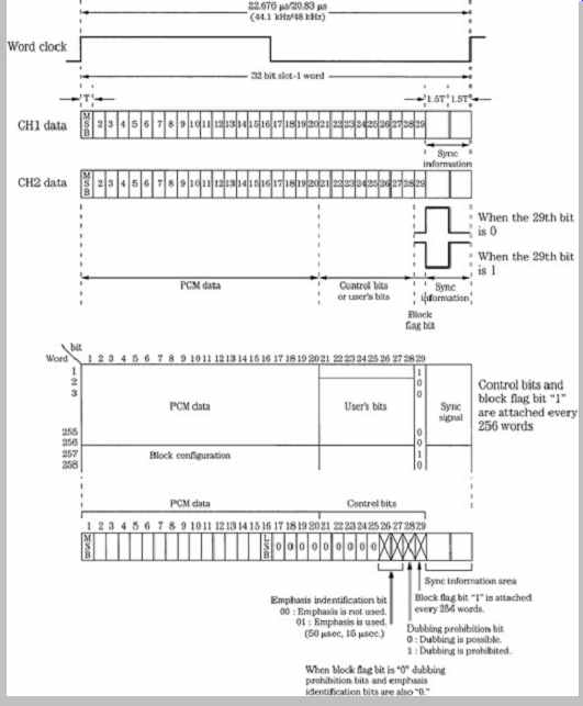
FIG. 1 The SDIF-2 interface is used to interconnect digital audio devices.
The control word conveys nonaudio data in the interface.
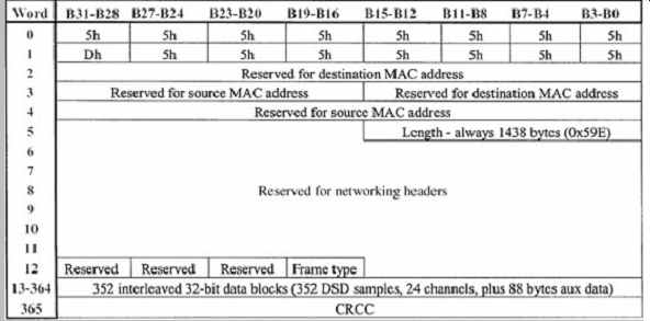
FIG. 2 The structure of a MAC-DSD audio data frame.
Audio data, control data, and check bits are interleaved within 32-bit data blocks. Each data block corresponds to a DSD sampling period.
AES3 (AES/EBU) Professional Interface
The Audio Engineering Society (AES) has established a standard interconnection generally known as the AES3 or AES/EBU digital interface. It is a serial transmission format for linearly represented digital audio data. It permits transmission of two-channel digital audio information, including both audio and nonaudio data, from one professional audio device to another. The specification provides flexibility within the defined standard for specialized applications; for example, it also supports multichannel audio and higher sampling frequencies. The format has been codified as the AES3-1992 standard; this is a revised version of the original AES3-1985 standard. In addition, other standards organizations have published substantially similar interface specifications: The International Electrotechnical Commission (IEC) IEC 60958 professional or broadcast use (known as type I ) format, the International Radio Consultative Committee (CCIR) Rec. 647 (1990), the Electronic Industries Association of Japan (EIAJ) EIAJ CP-340-type I format, the American National Standards Institute (ANSI ) ANSI S4.40 1985 standard, and the European Broadcasting Union (EBU) Tech. 3250-E.
The AES3 standard establishes a format for nominally conveying two channels of periodically sampled and uniformly quantized audio signals on a single twisted-pair wire. The format is intended to convey data over distances of up to 100 meters without equalization. Longer distances are possible with equalization. Left and right audio channels are multiplexed, and the channel is self-clocking and self-synchronizing. Because it is independent of sampling frequency, the format can be used with any sampling frequency; the audio data rate varies with the sampling frequency. A sampling frequency of 48 kHz ±10 parts per million is often used but 32, 44.1, 48, and 96 kHz are all recognized as standard sampling frequencies by the AES for pulse-code modulation (PCM) applications in standards document AES5-1998. Moreover, AES3 has provisions for sampling frequencies of 22.05, 24, 88.2, 96, 176.4, and 192 kHz. Sixty-four bits are conveyed in one sampling period; the period is thus 22.7 µs with a 44.1-kHz sampling frequency. AES3 alleviates polarity shifts between channels, channel imbalances, absolute polarity inversion, gain shifts, as well as analog transmission problems such as hum and noise pickups, and high frequency loss. Furthermore, an AES3 data stream can identify monaural/stereo, use of pre-emphasis, and the sampling frequency of the signal.
The biphase mark code, a self-clocking code, is the binary frequency modulation channel code used to convey data over the AES3 interconnection. There is always a transition (high to low, or low to high) at the beginning of a bit interval. A binary 1 places another transition in the center of the interval; a binary 0 has no transition in the center. A transition at the start of every bit ensures that the bit clock rate can be recovered by the receiver. The code also minimizes low-frequency content, and is polarity-free (information lies in the timing of transitions, not their direction). All information is contained in the code's transitions. Using the code, a properly encoded data stream will have no transition lengths greater than one data period (two cells), and no transition lengths shorter than one-half coding period (one cell). This kind of differential code can tolerate about twice as much noise as channels using threshold detection. However, its bandwidth is large, limiting channel rate; logical 1 message bits cause the channel frequency to equal the message bit rate. The overall bit rate is 64 times the sampling frequency; for example, it is 3.072 Mbps at a 48-kHz sampling frequency.
Channel codes are discussed in Section 3.
AES3 Frame Structure
The AES3 specification defines a number of terms. An audio sample is a signal that has been periodically sampled, quantized, and digitally represented in a two's complement manner. A subframe is a set of audio sample data with other auxiliary information. Two subframes, one for each channel, are transmitted within the sampling period; the first subframe is labeled 1 and the second is labeled 2. A frame is a sequence of two sub-frames; the rate of transmission of frames corresponds exactly to the sampling rate of the source. With stereo transmissions, subframe 1 contains left A-channel data and sub-frame 2 contains right B-channel data, as shown in FIG. 3A. For monaural, the rate remains at the two-channel rate, and the audio data is placed in subframe 1.
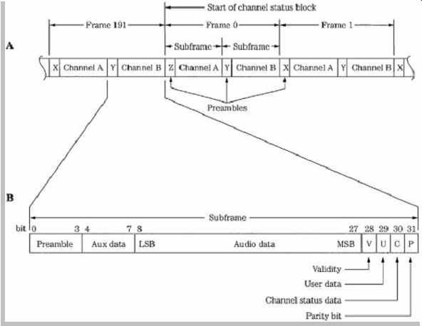
FIG. 3 The professional AES3 serial interface is structured in frames
and subframes as well as channel status blocks formed over 192 frames. A. There
are two subframes per frame; each subframe is identified with a preamble. B.
The interface uses a subframe of 32 bits.
A block is a group of channel status data bits and an optional group of user bits, one per subframe, collected over 192 source sample periods. A subframe preamble designates the starts of subframes and channel status blocks, and synchronizes and identifies audio channels.
There are three types of preambles. Preamble Z identifies the start of subframe 1 and frame 0, which is also the start of a channel status block. Preamble X identifies the start of subframe 1 otherwise, and Preamble Y identifies the start of sub-frame 2. Preambles occupy four bits; they are formed by violating the biphase mark coding in specific ways. Preamble Z is 3UI /1UI /1UI /3UI where UI is a unit interval. Preamble X is 3UI /3UI /1UI /1UI . Preamble Y is 3UI /2UI /1UI /2UI .
The format specifies that a subframe has a length of 32 bits, with fields that are defined as shown in FIG. 3B.
Audio data might occupy up to 24 bits. Data is linearly represented in two's complement form, with the least significant bit (LSB) transmitted first. If the audio data does not require 24 bits, then the first four bits can be used as an auxiliary data sample, as defined in the channel status data. For example, broadcasters might use the four auxiliary bits for a low bit-rate talkback feed. When devices use 16-bit words, the last 16 bits in the data field are used, with the others set to 0. Four bits conclude the subframe:
Bit V-An audio sample validity bit is 0 if the transmitted audio sample is error-free, and 1 if the sample is defective and not suitable for conversion to an analog signal. Bit U- A user data bit can optionally be used to convey blocks of user data. A recommended format for user data is defined in the AES18-1992 standard, as described below. Bit C- A channel status bit is used to form blocks describing information about the interconnection channel and other system parameters, as described below. Bit P-A subframe parity bit provides even parity for the subframe;
the bit can detect when an odd number of errors have occurred in the transmission.
AES3 Channel Status Block
The audio channel status bit is used to convey a block of data 192 bits in length. An overview of the block is shown in FIG. 4. Received blocks of channel status data are accumulated from each of the subframes to yield two independent channel status data blocks, one for each channel. At a sampling frequency of 48 kHz, the blocks repeat at 4-ms intervals. Each channel status data block consists of 192 bits of data in 24 bytes, transmitted as one bit in each subframe, and collected from 192 successive frames. The block rate is 250 Hz at a 48-kHz sampling frequency. The channel status block is synchronized by the alternate subframe preamble occurring every 192 blocks.
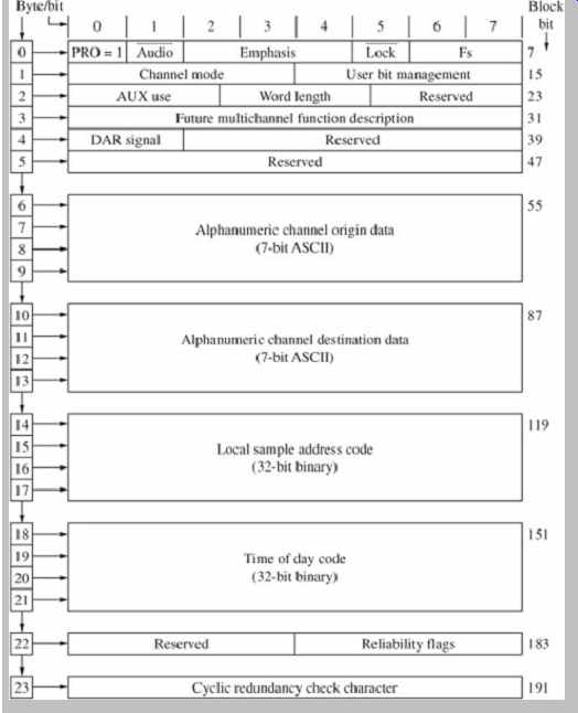
FIG. 4 Specification of the 24-byte channel status block used in the
AES3 serial interface.
There are 24 bytes of channel status data. The first six bytes (outlined at the top of FIG. 4) are detailed in FIG. 5. Byte 0 of the channel status block contains information that identifies the data for professional use, as well as information on sampling frequency and use of pre emphasis. With any AES3 communication, bit 0 in byte 0 must be set to 1 to signify professional use of the channel status block. Byte 1 specifies the signal mode such as stereo, monaural, or multichannel. Byte 2 specifies the maximum audio word length and number of bits used in the word; an auxiliary coordination signal can be specified.
Byte 3 is reserved for multichannel functions. Byte 4 identifies multichannel modes, type of digital audio reference signal (Grade 1 or 2) and alternative sampling frequencies. Byte 5 is reserved. Bytes 6 through 9 contain alphanumeric channel origin code, and bytes 10 through 13 contain alphanumeric destination code; these can be used to route a data stream to a destination, then display its origin at the receiver. Bytes 14 through 17 specify a 32-bit sample address. Bytes 18 through 21 specify a 32-bit time of-day timecode with 4-ms intervals at a 48-kHz sampling frequency; this timecode can be divided to obtain video frames. Byte 22 contains data reliability flags for the channel status block, and indicates when an incomplete block is transmitted. The final byte, byte 23, contains a cyclic redundancy check code (CRCC) codeword with the generation polynomial x8 + x4 + x3 + x2 + 1 across the channel status block for error detection.
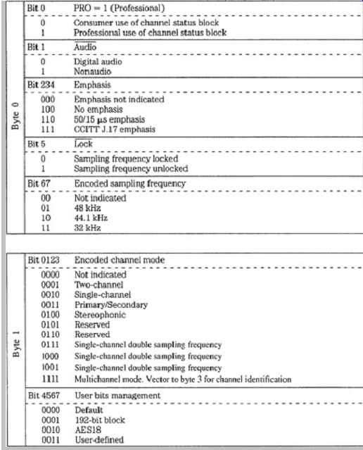

FIG. 5 Description of the data contained in bytes 0 to 5 in the 24-byte
channel status block used in the AES3 serial interface.
Three levels of channel status implementation are defined in the AES3 standard: minimum, standard, and enhanced. These establish the nature of the data directed to the receiving units. With the minimum level, the first bit of the channel status block is set to 1 to indicate professional status, and all other channel status bits are set to 0. With standard implementation, all channel status bits in bytes 0, 1, and 2 (used for sampling frequency, pre-emphasis, monaural/stereo, audio resolution, and so on) and CRCC data in byte 23 must be transmitted; this level is the most commonly used. With enhanced implementation, all channel status bits are used.
As noted, audio data can occupy 24 bits per sample.
When the audio data occupies 20 bits or less, the four remaining bits can be optionally used as an auxiliary speech-quality coordination channel, providing a path so that verbal communication can accompany the audio data signal. Such a channel could use a sampling frequency that is 1/3 that of the main data rate, and use 12-bit coding; one 4-bit nibble is transmitted in each subframe. Complete words would be collected over three frames, providing two independent speech channels. The resolution of the main audio data must be identified by information in byte 2 of the channel status block.
AES3 Implementation
In many ways, in its practical usage an AES3 signal can be treated similarly to a video signal. The electrical parameters of the format follow those for balanced-voltage digital circuits as defined by the International Telegraph and Telephone Consultative Committee (CCITT) of the International Telecommunication Union (ITU) in Recommendation V.11. Driver and receiver chips used for RS-422 communications, as defined by the Electronic Industries Association (EIA), are typically used; the EBU specification dictates the use of a transformer. The line driver has a balanced output with internal impedance of 110 ohm ± 20% from 100 kHz to 128 × the maximum frame rate. Similarly, the interconnecting cable's characteristic impedance is 110 ohm ± 20% at frequencies from 100 kHz to 128 × the maximum frame rate. The transmission circuit uses a symmetrical differential source and twisted-pair cable, typically shielded, with runs of 100 meters. Runs of 500 meters are possible when adaptive equalization is used. The waveform's amplitude (measured with a 110-ohm resistor across a disconnected line) should lie between 2 V and 7 V peak-to-peak. The signal conforms to RS-422 guidelines.
Jitter tolerance in AES3 can be specified with respect to unit intervals (UI), the shortest nominal time interval in the coding scheme; there are 128 UIs in a sample frame.
Output jitter is the jitter intrinsic to the device as well as jitter passed through from the device's timing reference. Peak to-peak output jitter from an AES3 transmitter should be less than 0.025 UI when measured with a jitter highpass weighting filter. An AES3 receiver requires a jitter tolerance of 0.25 UI peak-to-peak at frequencies above 8 kHz, increasing with an inverse of frequency to 10 UI at frequencies below 200 Hz. Some manufacturers use an interface with an unbalanced 75-? coaxial cable (such as 5C2V type), signal level of 1 V peak-to-peak, and BNC connectors. This may be preferable in a video-based environment, where switchers are used to route and distribute digital audio signals, or where long cable runs (up to 1 kilometer) are required. This is described in the AES3 ID document.
The receiver should provide both common-mode interference and direct current rejection, using either transformers or capacitors. The receiver should present a nominal resistive impedance of 110 ohm ± 20% to the cable over a frequency range from 100 kHz to 128 × the maximum frame rate. A low-capacitance (less than 15 pF/foot) cable is greatly preferred, especially over long cable runs. Shielding is not critical, thus an unshielded twisted-pair (UTP) cable is used. If shielding is needed, braid or foil shielding is preferred over server (spiral) shielding. More than one receiver on a line can cause transmission errors. Receiver circuitry must be designed with phase-lock loops to reduce jitter. The receiver must also synchronize the input data to an accurate clock reference with low jitter; these tolerances are further defined in the AES11 standard. Input (female) and output (male) connectors use an XLR-type connector with pin 1 carrying the ground signal, and pins 2 and 3 carrying the unpolarized signal.
A simple multichannel version of AES3 uses a number of two-channel interfaces. It is described in AES-2id-1996 and combines 16 channels using a 50-pin D-sub type connector. Byte 3 of the channel status block indicates multichannel modes and channel numbers. AES42 is based on AES3. It can be used to connect a digital microphone in which A/D conversion occurs at the microphone. It adds provision for control, powering, and synchronization of microphones. The power signal can be modulated to convey remote control information.
Microphones using this interface are sometimes known as an AES3-MIC microphone.
Low bit-rate data can be conveyed via AES3. Because data rate is reduced, a number of channels can be conveyed in a nominally two-channel interface, packing data in the PCM data area. SMPTE 337M and the similar IEC 61937 standard describe a multichannel interface;
SMPTE 338M and 339M describe data types. For example, Dolby E data could be conveyed for professional applications and Dolby Digital, DTS, or MPEG for consumer applications. Dolby E can carry up to eight channels of audio plus associated metadata via conventional two-channel interfaces. For example, it allows 5.1-channel programs to be conveyed along one AES3 digital pair at a typical bit rate of 1.92 Mbps.
AES10 (MADI) Multichannel Interface The Multichannel Audio Digital Interface (MADI ) extends the AES3 protocol to provide a standard means of interconnecting multichannel digital audio equipment.
MADI , as specified in the AES10 standard, allows up to 56 channels of linearly represented, serial data to be conveyed along a single length of BNC-terminated cable for distances of up to 50 meters. Word lengths of up to 24 bits are permitted. In addition, MADI is transparent to the AES3 protocol. For example, the AES3 validity, user, channel status, and parity bits are all conveyed. An interconnection with the AES3 format requires two cables for every two audio channels (for send and return), but a MADI interconnection requires only two audio cables (plus a master synchronization signal) for up to 56 audio channels.
The MADI protocol is documented as the AES10-1991 and ANSI S4.43-1991 standards.
To reduce bandwidth requirements, MADI does not use a biphase mark code. Instead, an NRZI code is used, with 4/5 channel coding based on the Fiber Distributed Data Interface (FDDI ) protocol that yields low dc content; NRZI code is described in Section 3. Each 32-bit subframe is parsed into 4-bit words that are encoded to 5-bit channel words. The link transmission rate is fixed at 125 Mbps regardless of the sampling rate or number of active channels. One sampling period carries 56 channels, each with eight 5-bit channel symbols, that is, 32 data bits or 40 channel bits. Because of the 4/5 encoding scheme, the data transfer rate is thus 100 Mbps. Although AES3 is self clocking, MADI is designed to run asynchronously. To operate asynchronously, a MADI receiver must extract timing information from the transmitted data so the receiver's clock can be synchronized. To ensure this, the MADI protocol stipulates that a synchronization symbol is transmitted at least once per frame. Moreover, a dedicated master synchronization signal (such as defined by AES11) must be applied to all interconnected MADI transmitters and receivers.
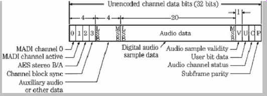
FIG. 6 The AES10 (MADI ) interface is used to connect multichannel digital
audio equipment. The MADI channel format differs from the AES3 subframe format
only in the first four bits.
The MADI channel format is based on the AES3 subframe format. A MADI channel differs from a subframe only in the first four bits, as shown in FIG. 6. Each channel therefore consists of 32 bits, with four mode identification bits, up to 24 audio bits, as well as the V, U, C, and P bits. The mode identification bits provide frame synchronization, identify channel active/inactive status, identify A and B subframes, and identify a block start. The 56 MADI channels are transmitted serially, starting with channel 0 and ending with channel 55, with all channels transmitted within one sampling period; the frame begins with bit 0 of channel 0. Because biphase coding is not used in the MADI format, preambles cannot be used to identify the start of each channel. Thus in MADI a 1 setting in bit 0 in channel 0 is used as a frame synchronization bit identifying channel 0, the first to be transmitted in a frame.
Bit 0 is set to 0 in all other channels. Bit 1 indicates the active status of the channel. If the channel is active it is set to 1, and if inactive it is set to 0. Further, all inactive channels must have a higher channel number than the highest-numbered active channel. The bit is not dynamic, and remains fixed after power is applied. Bit 2 identifies whether a channel is A or B in a stereo signal; this also replaces the function of the preambles in AES3. Bit 3 is set when the user data and status data carried within a channel falls at the start of a 192-frame block. The remainder of the MADI channel is identical to an AES3 sub-frame. This is useful because MADI and AES3 are thus compatible, allowing free exchange of data.
MADI uses coaxial cables to support 100 Mbps. The interconnection is designed as a transmitter-to-receiver single-point to single-point link; for send and return links, two cables are required. Standard 75-? video coaxial cable with BNC connector terminations is specified; peak to-peak transmitter output voltage should lie between 0.3 V and 0.6 V. Fiber-optic cable can also be used; for example, an FDDI interface could be used for distances of up to 2 kilometers. Alternatively, the Synchronous Optical NETwork (SONET) could be used. As noted, a distributed master synchronizing signal must be applied to all interconnected MADI transmitters and receivers. Because of the asynchronous operation, buffers are placed at both the transmitter and receiver, so that data can be reclocked from the buffers according to the master synchronization signal.
The audio data frequency can range from 32 kHz to 48 kHz, a ±12% variation is permitted. Higher sampling frequencies could be supported by transmitting at a lower rate, and using two consecutive MADI channels to achieve the desired sampling rate.
S/PDIF Consumer Interconnection
The S/PDIF (Sony/Philips Digital InterFace) interconnection protocol is designed for consumer applications. The IEC 60958 consumer protocol (known as type II ) is a substantially identical standard. In some applications, the EIAJ CP-340 type II protocol is used. IEC-958 was named IEC-60958 in 1998. These consumer standards are very similar to the AES3 standard, and in some cases professional and consumer equipment can be directly connected. However, this is not recommended because important differences exist in the electrical specification, and in the channel status bits, so unpredictable results can occur when the protocols are mixed. Devices that are designed to read both AES3 and S/PDIF data must reinterpret channel status block information according to the professional (1) or consumer (0) status is the block's first bit.
The overall structure of the consumer channel status block is shown in FIG. 7. It differs from the professional channel status block (see FIG. 4). The serial bits are arranged as twenty-four 8-bit bytes; only the first four bytes are defined.
FIG. 8 provides specific details on bytes 0 through 23. They differ from the professional AES3 channel status block (see FIG. 5). Byte 0, bit 0 is set to 0, indicating consumer use; bit 1 specifies whether the data is audio (0) or nonaudio (1); bit 2 is the copyright or C bit, and indicates copy-protected (0) or unprotected (1); bit 3 shows use of pre-emphasis (if bit 1 shows audio data and bits 4 and 5 show two-channel audio); bits 6 and 7 set the mode, that defines bytes 1 through 3. Presently, only mode 00 is specified. Byte 1, bits 0 through 6, define a category code that identifies the type of equipment transmitting the data stream; byte 1, bit 7 (the 15th bit in the block) is the generation or L bit, and indicates whether data is original or copied. If a recorder with an S/PDIF input receives an AES3 signal, it can read the professional pre-emphasis indicator as a copy-prohibit instruction, and thus refuse to record the data stream. Likewise, a professional recorder can correctly identify a consumer data stream by examining bit 0 (set to 0), but misinterpret a consumer copy-inhibit bit as a sign that emphasis is not indicated. In mode 00, the category code in byte 1 defines a variety of transmitting formats including CD, DAT, synthesizer, sample rate converter, and broadcast reception. Byte 2 specifies source number and channel number, and byte 3 specifies sampling frequency and clock accuracy.
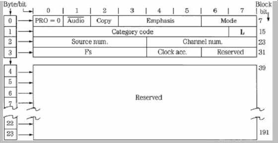
FIG. 7
Specification of the 24-byte channel status block used in the consumer S/PDIF
serial interface.
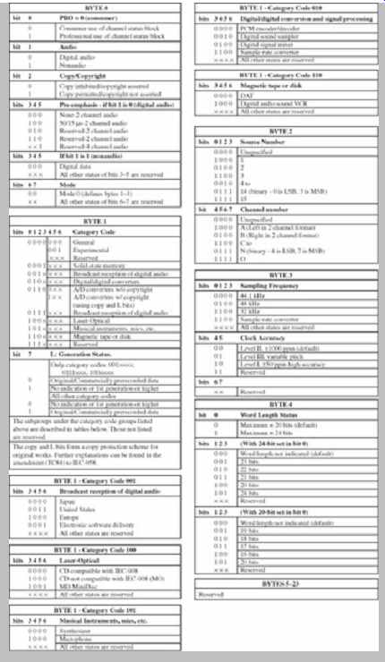
FIG. 8
Description of the data contained in the 24 byte channel status block used
in the S/PDIF serial interface.
The category code, as noted, defines different types of digital equipment. This in turn defines the subframe structure, and how receiving equipment will interpret channel status information. For example, the category code for CD players (100) defines the sub-frame structure with 16 bits per sample, a sampling frequency of 44.1 kHz, control bits derived from the CD's Q subcode, and places CD subcode data in the user bits. Subcode is transmitted as it is derived from the disc, one subcode channel bit at a time, over 98 CD frames. The P subcode, used to identify different data areas on a disc, is not transmitted. The start of subcode data is designated by a minimum of sixteen 0s, followed by a high start bit. Seven subcode bits (Q-W) follow. Up to eight 0s can follow for timing purposes, or the next start bit and subcode field can follow immediately. The process repeats 98 times until the subcode is transmitted.
Subcode blocks from a CD have a data rate of 75 Hz.
There is one user bit per audio sample, but there are fewer subcode bits than audio samples (12 × 98 = 1176) so the remaining bits are packed with 0s.
Unlike the professional standard, the consumer interface does not require a low-impedance balanced line. Instead, a single-ended 75-ohm coaxial cable is used, with 0.5 V peak to-peak amplitude, over a maximum distance of 10 meters.
To ensure adequate transmission bandwidth, video-type cables are recommended. Alternatively, some consumer equipment uses an optical Toslink connector and plastic fiber-optic cable over distances less than 15 meters. Glass fiber cables and appropriate code/decode circuits can be used for distances over 1 kilometer.
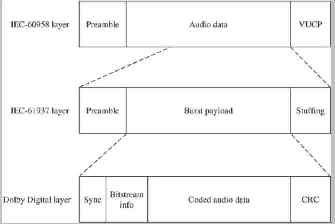
FIG. 9 The protocol stack used by the IEC-61937 standard to convey multichannel
data (such as Dolby Digital) via the IEC-60958 standard.
The IEC-61937 specification describes a multichannel interface. Low bit-rate data such as Dolby Digital, DTS, MPEG, or ATRAC can be substituted for the PCM data originally specified in the IEC-60958 protocol, as shown in FIG. 9. Because the data rate is reduced, a number of channels (such as 5.1 channels) can be conveyed in a nominally two-channel optical or coaxial interface.
Receiving equipment reads channel-status information to determine the type of bitstream (IEC-60958 or IEC-61937).
If the latter, the bitstream is directed to the appropriate decoder (such as Dolby Digital or DTS).
Serial Copy Management System
The Serial Copy Management System (SCMS) is used on many consumer recorders to limit the number of copies that many consumer recorders to limit the number of copies that can be derived from a recording. A user can make digital copies of a prerecorded, copyrighted work, but the copy itself cannot be copied; first-generation copying is permissible, but not second-generation copying. For example, a user can digitally copy from a CD to a second media, but a copy-inhibit flag is set in the second media's subcode so that it is impossible to digitally copy from the second media. However, a SCMS-equipped recorder can record any number of digital copies from an original source. SCMS does not affect analog copying in any way.
SCMS is a fair solution because it allows a user to make a digital copy of purchased software, for example, for compilation of favorite songs, but helps prevent a second party from copying music that was not paid for. On the other hand, SCMS might prohibit the recopying of original recordings, a legitimate use. Use of SCMS is mandated in the United States by the Audio Home Recording Act of 1992, as passed by Congress to protect copyrighted works.
The SCMS algorithm is found in consumer-grade recorders with S/PDIF (IEC-60958 type II ) interfaces; it is not present in professional AES3 (IEC-60958 type I ) interfaces. In particular, SCMS resides in the channel status bits as defined in IEC-60958 type II , Amendment No. 1 standard. This data is used to determine whether the data is copyrighted, and whether it is original or copied.
The SCMS circuit first examines the channel status block (see FIG. 7) in the incoming digital data to determine whether it is a professional bitstream or a consumer bitstream. In particular, when byte 0, bit 0 is a 1, the bitstream is assumed to adhere to the AES3 standard; SCMS takes no action. SCMS signals do not appear on AES3 interfaces, and the AES3 standard does not recognize or carry SCMS information; thus, audio data is not copy-protected, and can be indefinitely copied. When bit 0 is set to 0, the SCMS identifies the data as consumer data. It examines byte 0, bit 2, the copyright or C bit; it is set to 0 when copyright is asserted, and set to 1 when copyright is not asserted. Byte 1, bit 7 (the 15th bit in the block) is the generation or L bit; it is used to indicate the generation status of the recording.
For most category codes, an L bit of 0 indicates that the transmitted signal is a copy (first-generation or higher) and a 1 means that the signal is original. However, the L bit may be interpreted differently by some product categories. For example, the meaning is reversed for laser optical products other than the CD: 0 indicates an original, and 1 indicates a copy. The L bit is thus interpreted by the category code contained in byte 1, bits 0 to 6 that indicate the type of transmitting device. In the case of the Compact Disc, because the L bit is not defined in the CD standard (IEC 908), the copy bit designates both the copyright and generation. Copyright is not asserted if the C bit is 1; the disc is copyrighted and original if the C bit is 0; if the C bit alternates between 0 and 1 at a 4-Hz to 10-Hz rate, the signal is first-generation or higher, and copyright has been asserted. Also, because the general category and A/D converter category without copyrighting cannot carry C or L information, these bits are ignored and the receiver sets C for copyright, and L to original.
Generally, the following recording scenario exists when bit 0 is set to 0, indicating a consumer bitstream: When bit C is 1, incoming audio data will be recorded no matter what is written in the category code or L bit, and the new copy can in turn be copied an unlimited number of times.
When bit C is 0, the L bit is examined; if the incoming signal is a copy, no recording is permitted. If the incoming signal is original, it will be recorded, but the recording is marked as a copy by setting bits in the recording's subcode; it cannot be copied. When no defined category code is present, one generation of copying is permitted.
When there is a defined category code but no copyright information, two generations are permitted. However, different types of equipment respond differently to SCMS.
For example, equipment that does not store, decode, or interpret the transmitted data, is considered transparent and ignores SCMS flags. Digital mixers, filters, and optical disc recorders require different interpretations of SCMS; the general algorithm used to interpret SCMS code is thus rather complicated.
By law, the SCMS circuit must be present in consumer recorders with the S/PDIF or IEC-60958 type II interconnection. However, some professional recorders, essentially upgraded consumer models, also contain an SCMS circuit. If recordists use the S/PDIF interface, copy inhibit flags are sometimes inadvertently set, leading to problems when subsequent copying is needed.
High-Definition Multimedia Interface (HDMI) and DisplayPort
The High-Definition Multimedia Interface (HDMI ) provides a secure digital connection for television and computer video, and multichannel audio. HDMI conveys full-bandwidth video and audio and is often used to connect consumer devices such as Blu-ray players and television displays. HDMI is compliant with HDCP (High-band-width Digital Content Protection). HDMI Version 1.0 was introduced in 2003, and has been improved in subsequent versions. For example, Version 1.0 permitted a throughput of 4.9 Gbps, and Version 1.3 permitted 10.2 Gbps. Version 1.4 adds an optional Ethernet channel and an optional audio return channel between connected devices. Version 1.4 also defines specifications for conveying 3D movie and game formats in 1080p/24 and 720p/60 resolution; Version 1.4a supports 3D broadcast formats.
The DisplayPort interface conveys video and audio data via a single cable connection and is an open-standard alternative to HDMI. DisplayPort is compatible with HDMI 1.3 and adapters can be used to interconnect them.
DisplayPort 1.1 provides a throughput of 10.8 Gbps and also supports HDCP.