Early personal computers were little more than programmable calculators, with almost no audio capabilities. A PC typically contained a tiny speaker that was used to emit prompt beeps. The idea of making music was virtually improbable. In one celebrated demonstration, an early enthusiast programmed his computer so that when an AM radio was placed nearby, the interference from the meticulously programmed digital circuits produced rhythmic static in the radio that, in the broadest sense of the word, could be interpreted as the musical theme from Rossini's William Tell overture.
With the advent of more powerful hardware and software, personal computers became more adept at making music. In particular, audio chip sets became staples in PCs. Containing synthesis chips and A/D and D/A converters, these systems are used to play MIDI files, sound effects, and to record and play back WAV files.
Simultaneously, CD-ROM and DVD-ROM drives became common, and are used to play audio CDs as well as DVD Video movies. Multichannel speakers and subwoofers are common accessories in the PC market. The PC industry has adopted audio technologies such as the CD, DVD, Blu-ray, 3D audio, and sound synthesis, and contributed computer technologies such as the PCI bus, Win98, MMX, AC '97, IEEE 1394, and USB. These individually diverse improvements allow an integration of technologies, and bring a new level of fidelity and features to PC digital audio and multimedia in general. Moreover, the personal computer has become the nucleus of both professional and personal recording studios in a wide variety of applications.
PC Buses and Interfaces
Internal and external peripherals can be interfaced to a host computer with any of several interconnections. IBM-PC computers historically contained the ISA (Industry Standard Architecture) local bus; its 11-Mbyte/second transfer rate limits audio applications. A stereo CD data stream, at 1.4 Mbps, along with sound effects and several voices might consume 40% of the bus, leaving little capacity for the multitasking operating system. The EISA (Extended ISA) local bus offers a 32-Mbyte/second rate and other improvements, but is also limited for audio applications.
The PCI (Peripheral Component Interconnect) is a high performance local interconnection bus. PCI provides a maximum 132-Mbyte/second transfer rate, 32-bit pathways, good noise immunity, and efficiently integrates the computer's processor and memory with peripherals. The PCI bus is lightly taxed with even multiple audio streams.
Moreover, the PCI bus outperforms the ISA and EISA bus in terms of latency. An audio output must be free of any interruptions in the flow of audio data. Because of its high performance, the PCI bus allows cooperative signal processing in which tasks are balanced between the host processor and an audio accelerator. For these and other reasons, the PCI bus replaced the ISA bus. Microsoft's PC98 specification decreed that new logos would no longer be issued to ISA audio products. The PCI bus is found on both Macintosh and IBM-PC computers.
The ATA (Advanced Technology Attachment) bus was designed as the expansion slot format for the PC providing a 16-bit path width and burst speeds up to 8.3 Mbyte/second; it is also known as the IDE (Integrated Drive Electronics) bus. Faster variants include EIDE (Enhanced Integrated Drive Electronics) or ATA-2 and Ultra ATA (ATA-3 or Ultra DMA). ATA-2 accommodates burst speeds up to 16 Mbytes/second, and ATA-3 accommodates speeds up to 33.3 Mbytes/second. The PCMCIA (Personal Computer Memory Card International Association) is used on notebook computer expansion ports.
Some computers use SCSI (Small Computer System Interface) connections. SCSI (pronounced "scuzzy") is a high-speed data transfer protocol that allows multiple devices to access information over a common parallel bus.
Transmitting (smart) devices initiate SCSI commands; for example, to send or request information from a remote device. Likewise, receiving (dumb) devices accept SCSI commands; for example, a hard disk can only receive commands. Some devices (sometimes called logical devices) are classified as transmitter/receivers; computers are grouped in this category.
The SCSI protocol allows numerous devices to be daisy-chained together; each device is given a unique identification number; numbers can follow any order in the physical chain. A SCSI cable can extend to 12 meters. A device must have two SCSI ports to allow chaining; otherwise, the device must fall at the end of the chain.
Generally, the first and last physical devices (determined physically, not by identification number) in a chain must be terminated; intermediate devices should not be terminated.
Termination can be internal or external; devices that are externally terminated allow greater liberty of placement in the chain.
SCSI defines a number of variants, differing principally in data path width and speed, as well as physical connectors. The basic SCSI-1 width (number of bits in the parallel data path) is 8 bits (narrow). In addition, 16-bit (wide) and 32-bit (very wide) versions are used. The basic SCSI-1 data transmission rate is 12.8 Mbps, that is, 1.6 Mbyte/second; all data transfer is asynchronous. Other speeds include Fast, Ultra, Ultra 2, and Ultra 3. For example, Ultra 2 can accommodate transfers of up to 80 Mbyte/second. Narrow SCSI devices use 50-pin connectors, and wide devices use 68-pin connectors.
Alternatively, the Enhanced-IDE/ATAPI interface can be used to connect computers and peripherals at speeds of 13.3 Mbyte/second over short (18 inch) cables. Fast ADA 2 hard-drive interfaces can operate at 16.6 Mbyte/second. However, unlike SCSI , these are simple interfaces that do not support intelligent multitasking. To overcome many interconnection installation problems in PCs, the Plug and Play standard was devised. The operating system and system BIOS automatically configure jumper, IRQ, DMA address, SCSI IDs, and other parameters for the plug-in device. Many DVD-ROM drives use E-IDE/ATAPI or SCSI - 2 interfaces. The SFF 8090i Mt. Fuji standard allows the ATAPI and SCSI interfaces to fully support DVD reading of regional codes, decryption authentication, CSS and CPRM data, BCA area, and physical format information.
IEEE 1394 (FireWire)
The Institute of Electrical and Electronics Engineers (IEEE) commissioned a technical working group to design a new data bus transmission protocol. Based on the FireWire protocol devised by Apple Computer, the IEEE 1394-1995 High Performance Serial Bus standard defines the physical layer and controller for both a backplane bus and a serial data bus that allows inexpensive, general purpose, high speed data transfer; the latter is discussed here. The IEEE 1394 cable bus is a universal, platform-independent digital interface that can connect digital devices such as personal computers, audio and video products for multimedia, digital cable boxes and HDTV tuners, printer and scanner products, digital video cameras, displays, and other devices that require high-speed data transfer. For example, a digital camcorder can be connected to a personal computer for transferring video/audio data. Wireless Fire Wire technology has also been developed, using IEEE 802.15.3 technology.
The IEEE 1394 cable standard defines three data rates:
98.304, 196.608, and 393.216 Mbps. These rates are rounded to 100, 200, and 400 Mbps, and are referred to as S100, S200, and S400. The latter is also known as FireWire 400. These rates permit transport, for example, of 65, 130, and 260 channels of 24-bit audio, sampled at 48 kHz. The IEEE 1394b standard enables rates from 800 Mbps to 3.2 Gbps. More details of IEEE 1394b are given below. The 1394c standard merges FireWire and Ethernet technologies.
The IEEE 1394 connecting cable is thin (slightly thicker than a phone cable) and uses copper wires; there are two separately shielded twisted-pair transmission lines for signaling, two power conductors, and a shield. A four conductor version of the standard cable with no power connectors is used in some consumer audio/video components. It is defined in IEEE 1394.1 and is sometimes known as i.Link. (IEEE 1394, FireWire and i.Link are all functionally equivalent and compatible.) The two twisted pairs are crossed in each cable assembly to form a two way transmit-receive connection. The IEEE 1394 connector (the same on both cable ends) is small and rugged (and derived from Nintendo's GameBoy connector). It uses either a standard friction detent or a special side-locking tab restraint, as shown in FIG. 1. Since it can deliver electrical power (8 to 40 volts, up to 1.5 amperes), an IEEE 1394 cable can be used as the sole connecting cable to some devices. It is similar to a SCSI cable in that it can be used as a point-to-point connection between two devices, or devices can be connected with branches or daisy chained along lengths of cable. However, unlike SCSI , no addressing (device ID) or termination is needed. In some cases, IEEE 1394 is used with other cabling such as Category 5 twisted pair and optical fiber. With 50-mm multimode fiber, for example, cable runs of hundreds of meters are permitted. However, more robust clocking methods are required.
A cable can run for 4.5 meters between two devices without a repeater box (this length is called a hop) and there may be up to 16 cable hops in a line, extending a total distance of up to 72 meters with standard cable (longer distances are possible with higher quality cable). Up to 63 devices can be directly connected into a local cluster before a bus bridge is required, and up to 1023 clusters can be connected via data bridges. IEEE 1394 can be used equally well to connect two components or run throughout an entire home or office to interconnect electronic appliances. IEEE 1394 is "hot-pluggable" so that users can add or remove devices from a powered bus. It is also a scalable architecture, so users can mix multiple speed devices on one bus.
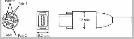
FIG. 1 The IEEE 1394 connector (the same on both cable ends) forms a
two-way transmit-receive connection carrying two twisted-pair signal cables,
and power.
IEEE 1394 defines three layers: physical, link, and transaction. The physical layer defines the signals required by the IEEE 1394 bus. The link layer formats raw data (from the physical layer) into recognizable IEEE 1394 packets.
The transaction layer presents packets (from the link layer) to the application.
The IEEE 1394 bus data rate is governed by the slowest active node. However, the bus can support multiple signaling speeds between individual node pairs.
Considering that the rate of a stereo digital audio bitstream may be 1.4 Mbps, a compressed video stream may also be 1.4 Mbps, and an uncompressed broadcast-quality video stream may be 200 Mbps, an IEEE 1394 interface can accommodate multimedia data loads.
When a connection is made, the bus automatically reinitializes the entire bus, recognizing the new device and integrating it with other networked devices, in less than 125 µs. Similarly, upon disconnection, IEEE 1394 automatically reconfigures itself. Asynchronous transmission performs simple data transfers. As with all asynchronous transmission, a chunk of data is transferred after acknowledgement that a previously transmitted chunk has been received. Since this timing cannot be predicted because of other network demands, timing of delivery is random; this is problematic for real-time audio and video data.
Real-time, data-intensive applications such as uncompressed digital video can be provided bandwidth and low latency, using isochronous transmission. With isochronous transmission, synchronized data such as audio and video will be conveyed with sufficiently small discrepancy so that they can be synchronized at the output.
Instead of a send/acknowledgement method, isochronous transmission guarantees bus bandwidth for a device.
Nodes request a bandwidth allocation and the isochronous resource manager uses a Bandwidth Available register to monitor the bandwidth available to all isochronous nodes.
All bus data is transmitted in 32-bit words called quadlets and bandwidth is measured in bandwidth allocation units. A unit is about 20 ns, the time required to send one data quadlet at 1600 Mbps. The isochronous resource manager uses its Channels Available register to assign a channel number (0 to 63) to a node requesting isochronous bandwidth. This channel number identifies all isochronous packets. When a node completes its isochronous transfer, it releases its bandwidth and channel number. A bus manager such as a PC is not needed; any "talker" device can act as the isochronous resource manager to create a single, fixed isochronous channel.
Using the common timebase of isochronous transmission, data packets can be encoded with a small equalizing time delay, so the output is exactly synchronized with the clock source-a critical feature for audio and video data words that must arrive in order and on time. This feature is particularly crucial when an IEEE 1394 cable is handling simultaneous transmissions between different devices. Isochronous transmissions are given priority status in the time-multiplexed data stream so that an audio and video transfer, for example, is not disrupted by a control command. Whereas some interfaces are expensive because large memory buffers are needed to temporarily store data at either cable end, IEEE 1394 does not need large buffers. Its just-in-time data delivery allows devices to exchange data or commands directly between their internal memories.
The IEEE 1394 specification includes an "Audio and Music Data Transmission Protocol" (known as the A/M protocol) that defines how real-time digital audio can be conveyed over IEEE 1394 using isochronous packets.
Data types include IEC-958 and raw audio samples (in data fields up to 24-bits in length) as well as MIDI files (with up to 3 bytes per field); it is standardized as IEC 61883 1/FDIS. This protocol, and multi-channel versions, provide sufficient bandwidth to convey DVD-Audio data streams of 9.6 Mbps. Copy-protection methods are used to guard against piracy of these high-quality DVD-Audio signals.
The mLAN specification can be used to send multiple sample-accurate AES3 signals, raw audio, MIDI , and other control information over an IEEE 1394 bus. The mLAN protocol uses an isochronous transfer mode that ensures on-time delivery and also prevents collisions and reduces latency and jitter. The specification reduces jitter to 20 ns, and when phase-locked loops are used at individual mLAN nodes, jitter can be further reduced to 1 ns. Up to 63 devices can be connected in any topology, ports are hot pluggable and software patching is routinely used. A portion of mLAN was adopted by the 1394 Trade Association as a supplemental standard for handling audio and music control data over the IEEE 1394 bus. mLAN was developed by Yamaha Corporation.
The first implementations of the 1394b standard, with throughput of 800 Mbps and 1600 Mbps, are also known as S800 and S1600. IEEE 1394b allows daisy-chaining of multiple peripherals. It also allows cable lengths of up to 800 meters for networks using twisted pair CAT-5 and plastic optical fiber. The Bus Owner Supervisor/Selector (BOSS) protocol allows data packets to be transmitted more efficiently, using less network bandwidth. IEEE 1394b ports use a different physical configuration than 1394; adapter cables are needed for compatibility.
IEEE 1394 is a non-proprietary standard and many standards organizations and companies have endorsed the standard. The Digital VCR Conference selected IEEE 1394 as its standard digital interface. An EIA subcommittee selected IEEE 1394 as the point-to-point interface for digital TV as well as the multi-point interface for entertainment systems. Video Electronics Standards Association (VESA) adopted IEEE 1394 for home networking. The European Digital Video Broadcasters also endorsed IEEE 1394 as their digital television interface.
Microsoft first supported IEEE 1394 in the Windows 98 operating system, and it is supported in newer operating systems. IEEE 1394 was first supported by the Macintosh operating system in 1997; Apple Computer supports IEEE 1394 on its computer motherboards.
IEEE 1394 may appear in PCs, satellite receivers, camcorders, stereos, VCRs, printers, hard drives, scanners, digital cameras, set-top boxes, music keyboards and synthesizers, cable modems, CD-ROM drives, DVD players, DTV decoders, and monitors. In some applications, such as when connecting to displays, Digital Transmission Content Protection (DTCP) technology is used to encrypt data, allowing secure, two-way transmission of digital content across an IEEE 1394 interface.
Digital Transmission Content Protection (DTCP)
The security of transmitted data is an important issue in many applications. The Digital Transmission Content Protection (DTCP) system was devised for secure (anti piracy) transmission in the home environment over bi-directional digital lines such as the IEEE 1394 bus.
Sometimes known as "5C," it was devised by a consortium of companies including Sony, Toshiba, Intel, Hitachi, and Matsushita, as well as the Motion Picture Association of America. DTCP prevents unauthorized copying of digital content while allowing legitimate copying for purposes such as time-shifting. Connected devices trade keys and authentication data, the transmitting device encrypts the signal, and the receiving device decrypts it. Devices such as video displays identify themselves as playback-only devices and can receive all data. Recorders can only receive data marked as copy-permitted, and must update and pass along Copy Control Information (CCI ). DTCP does not affect other copy protection methods that may be employed on DVD or Blu-ray discs, satellite broadcasts, and so on. DTCP uses encryption on each digital link. Each device on a link obeys embedded CCI that specifies permitted uses of content: Copy-Never (no copies allowed, display only), Copy-One-Generation (one copy allowed), Copy-No-More (prevents making copies of copies), and Copy-Freely (no copy restrictions). Two-way "challenge and response" communication provided by the Authentication and Key Exchange system enables source components in the home to confirm the authenticity of receiving components.
DTCP can revoke the privileges of rogue equipment attempting to defeat the system, obtain encryption keys, and so on. To do this, each piece of consumer equipment contains System Renewability Messages (SRMs), a list of serial numbers of individual pieces of equipment used in piracy. SRMs are updated through packaged software, transmissions, and new equipment, and are automatically passed along to other components. Source components re-encrypt data to be transmitted to receiving components; encryption keys are changed as often as every 30 seconds.
The Digital Transmission Licensing Administrator (DTLA) was established to license the content-protection system and to generate and distribute cryptographic materials such as keys and certificates. DTCP is designed for use in HDTV receivers, set-top boxes, digital recorders, satellite receivers, and other consumer components. Encryption and water-marking are discussed in Section 15.
Universal Serial Bus (USB)
The Universal Serial Bus (USB) was designed to replace older computer serial (and parallel) I /O buses, to provide a faster, more user-friendly interconnection method, and to overcome the limitation of too-few free interrupts available for peripherals. Computer keyboards, mice, cable modems, telephones, ROM drives, flash memories, printers, scanners, digital cameras, multimedia game equipment, MIDI devices, and loudspeakers are all candidates for USB. Unlike IEEE 1394, which permits interconnection between any two enabled devices, USB requires a microprocessor-based controller, and hence it is used primarily for PC peripherals. A few USB ports can replace disparate back-panel connectors.
The original USB specification, known as USB 1.1, provides low-speed interconnection. The newer USB 2.0 specification (sometimes known as "Hi-Speed USB") provides data rates that are 40-times faster than USB 1.1.
The USB 1.1 specification provides a transfer rate of 12 Mbps (about 1 Mbps of this is used for overhead). This transfer rate is sufficient for applications employing S/PDIF, AC-3, and MPEG-1, as well as some MPEG-2 applications. There is also a 1.5-Mbps subchannel available for low data-rate devices, such as a mouse. USB 2.0 offers transfer rates up to 480 Mbps. This allows connection to high-speed ROM drives and in particular allows rapid transfer of large video files. USB 2.0 is fully compatible with 1.1 devices; however, 1.1 devices cannot operate at the faster speed. USB 2.0 uses the same connectors and cables as USB 1.1.
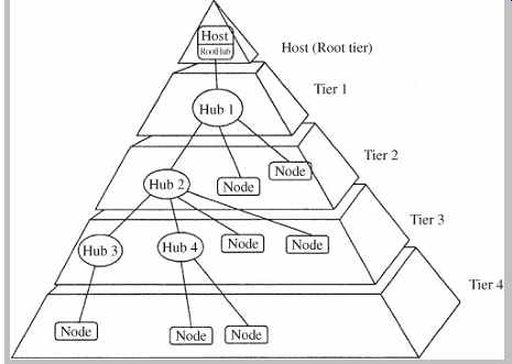
FIG. 2 The USB interconnect uses a tiered-star topology, with a hub at
the center of each star. Each cable forms a point-to-point connection between
the host and a hub or function, or a hub connected to another hub or function.
USB is SCSI-like in its ability to support up to 127 devices per port/host in a plug-and-play fashion. Moreover, USB devices can be hot-swapped without powering down the system. USB detects when a device is added or withdrawn, and automatically reinitializes the system. USB uses a tiered star topology in which only one device, such as a monitor or DVD-ROM drive, must be plugged into the PC's host (root) connector, as shown in FIG. 2. There is only one host in any system. It becomes a hub and additional devices can be connected directly to that hub or to additional hubs, using cable runs of 5 meters (full-speed devices) and 3 meters (low-speed devices). The host polls connected devices and initiates all data transfers.
USB hubs may be embedded in peripheral devices or exist as stand-alone hubs. Hubs contain an upstream connection port (pointed toward the PC) as well as multiple downstream ports to connect peripheral devices. USB uses a four-wire connector; a single twisted pair carries bidirectional data (one direction per wire), and there are 5 V power and ground conductors to deliver electrical power to low-power (500 mA, or 100 mA for a bus-powered hub) peripheral devices. The typical detachable cable is known as an "A to B" cable. "A" plugs are always oriented upstream toward the host ("A" receptacles are downstream outputs from the host or hub). "B" plugs are always oriented downstream toward the USB device ("B" receptacles are upstream inputs to the device or hub). An "A" and "B" cable assembly is shown in FIG. 3. All detachable cables must be full-speed.
USB host controllers manage the driver software and bandwidth required by each peripheral connected to the bus, and allocate electrical power to USB devices. Both USB host controllers and USB hubs can detect attachments and detachments (for device identification and dynamic reconfiguration) of peripherals using biased termination at cable ends. Hubs are required for multiple connections to the host connector. All devices have an upstream connection; hubs include downstream connections. Upstream and downstream connectors are polarized to prevent loop-back. Hubs can have up to seven connectors to nodes or other hubs, and may be self powered or powered by the host. Two PCs can be connected to each other with a specialized USB peripheral known as a USB bridge (sometimes called a USB-to-USB adapter). A direct PC-to-PC connection using an illegal "A to A" cable could short the two PCs' power supplies together, creating a fire hazard.
FIG. 3 Physical specifications for the USB detachable cable. "A" plugs orient upstream toward the host and "B" plugs orient downstream. The cable carries one twisted pair cable, and power.
The USB On-the-Go (USB OTG) supplement to the USB specification is used for portable devices such as cell phones and digital cameras. It allows limited hosting capabilities for direct point-to-point communication with selected peripherals. Devices can be either a host or peripheral and can dynamically switch roles. In addition, a smaller connector and low-power features are implemented. USB OTG is designed to supplant the many proprietary connections used in docking stations and slot connectors. USB OTG devices are compliant with the USB 2.0 specification.
USB is well-suited for transport of audio signals.
Standardized audio transport mechanisms are used to minimize software driver complexity. A robust synchronization scheme for isochronous transfers is incorporated in the USB specification. In particular, USB provides asynchronous transfer, but isochronous transfer is used for relatively higher-bandwidth (audio and video) devices. Isochronous transfer yields low jitter but increased latency. The transfer rate for a 16-bit, 48-kHz stereo signal is 192 bytes/ms. To maintain a correct phase relationship between physical audio channels, an audio function is required to report its internal delay to every audio streaming interface. The delay is expressed in number of frames (ms) and is caused by the need to buffer frames to remove packet jitter and by some audio functions that introduce additional delay (in integer numbers of frames) as they interpret and process audio streams. Host software uses delay information to synchronize different audio streams by scheduling correct packet timings. Phase jitter is limited to ±1 audio sample.
USB has many practical audio applications. For example, USB allows designers to bypass potentially poor D/A converters on motherboards and sound cards, and instead use converters in the peripheral device. For example, USB loudspeakers have D/A converters and power amplifiers built-in, so the speaker can receive a digital signal from the computer. USB loudspeakers obviate the need for sound cards in many implementations, and simplify the connection of PCs to outboard converters, digital signal processors, Dolby Digital decoders, and other peripherals.
Sound Card and Motherboard Audio
Most computer motherboards and sound cards contain A/D and D/A converters and hardware- and software-based processing to permit recording and playback of stereo 8 or 16-bit audio at multiple sampling rates. They also allow playback via wavetable synthesis, sampled sound, or FM synthesis. They provide digital I /O; ROM drive interfaces; a software-controlled audio mixer; onboard power amplifiers; and may also provide analog line-in and line-out, S/PDIF input and output, microphone input, and a gamepad/joystick/MIDI connector. Sound cards plug into an expansion slot and are accompanied by the appropriate software that is bundled with the card. The most basic part of the software regimen is the device drivers needed to control the various audio components.
Sound synthesis capabilities are used to create sound effects when playing MIDI files or playing video games. A sampled sound synthesizer plays stored sound files-for example, SND or AIFF (Audio Interchange File Format) files. Most chip sets support sample-based wavetable synthesis; this allows synthesis and playback of both music and sound effects via software. With wavetable synthesis, a particular waveform is stored in ROM, and looped through to create a continuous sound. Some audio chip sets support physical model-based waveguide synthesis in which mathematical models are used to emulate musical instrument sounds. In terms of synthesis ability, a chip may support 128 wavetable instruments, with many variation sounds and multiple drum sets using onboard RAM.
Moreover, 64 voices may be supported, with multi-timbral capability on 16 channels. Most chips have a MIDI interface for connection to an external MIDI hardware instrument such as a keyboard. A chip set may also contain built-in 3D stereo enhancement circuitry. These proprietary systems, in greater or lesser degrees, increase depth and breadth of the stereo soundstage, and broaden the "sweet spot" where channel separation is perceived by the listener.
Some chip sets include a DSP chip that allows hardware data reduction during recording and playback, and others provide resident non-real-time software data reduction algorithms. In addition, some chips provide voice recognition capability. These topics are discussed in more detail below.
Music Synthesis
From their origins as simple MIDI synthesizers employing FM synthesis, computer sound systems have grown in complexity. Diverse synthesis methods are employed, and the quality of rendered music varies dramatically with the type of synthesizer hardware installed. Many synthesizers generate audio signals from a file consisting of a table of audio samples. Traditionally, these tables are filled with single cycles of simple basis waveforms such as sinusoids or triangle waves. Complex sounds are generated by dynamically mixing the simple signals using more sophisticated algorithms. This is known as traditional wavetable synthesis. During playback, a pointer loops through the table continuously reading samples and sending them to a D/A converter. Different pitches are obtained by changing the rate at which the table is read.
For higher pitches, the processor skips samples; for example, to double the frequency, every other sample is read. Noninteger higher pitches are accomplished by skipping samples and interpolating new values. For lower pitches, the processor adds samples by interpolating values in-between those in the table. In both cases, the sample rate at the D/A converter remains constant. By dynamically mixing or crossfading different basis waveforms, complex sounds can be generated with low data storage overhead; a table may be only 512 samples in length.
Sample-based synthesis uses short recordings of musical instruments and other natural sounds for the basis waveforms. However, instead of perhaps 512 samples per table, these synthesizers may use thousands of samples per table. Because musical events may last several seconds or more, considerable memory would be required.
However, most musical events consist of an attack transient followed by a steady-state sustain and decay.
Therefore, only the transient portion and a small section of the steady-state portion need to be stored. Sound is created by reading out the transient, then setting up a wavetable-like loop through the steady-state section.
Because sample-based synthesis also uses wave lookup tables, the term "wavetable synthesis" became synonymous with both technologies and the two terms are used interchangeably. However, contemporary "wavetable synthesis" chips are really sample-based instruments. The quality of the synthesis depends on the quality of the initial recording, size of the table, and location of the loop points.
Short, low-resolution tables produce poor quality tones.
Although a sound card may claim "CD-quality," table resolution may only be 8, 12, or 14 bits, and not the 16-bit CD standard.
In physical modeling synthesis, the sound of a vibrating system (such as a musical instrument) is created using an analogous software model. For example, a plucked string vibrates as transverse waves propagating along the length of a string. The vibrations decay as the waves lose energy.
A string model might consist of an impulse, traveling through a circular delay line (or memory buffer), with its output connected back to the input through an attenuator and filter. The filtering and attenuation cause the impulse to simultaneously decay in amplitude and become more sinusoidal in nature, emulating a vibrating string. The length of the buffer controls pitch, and the filter and attenuator provide the correct timbre and decay. Physical modeling is attractive because it is easily implemented in software. It can produce consistent results on different computers, and the coded algorithms are quite short; however, relatively fast processors are needed to synthesize sound in real time.
In pure software synthesis, sounds are created entirely on the host computer, rather than in a dedicated sound chip. Software synthesizers can be distributed on disc or as downloadable files. Some downloadable software synthesizers are available as browser plug-ins for network applications.
Surround Sound Processing
Stereo playback can convey a traditional concert soundstage in which the sound comes mainly from the front.
However, stereo signals cannot convey ambient sounds that come from all around the listener. Stereo's lack of spatiality undermines sonic realism, for example, in a game where aircraft fly overhead from front to back. The lack of spatiality is exacerbated by the narrow separation between speakers in most PC playback systems. To provide a more convincing sound field, various algorithms can modify stereo signals so that sound played over two speakers can seem to come from around the listener. Alternatively, adequately equipped PCs can convey discrete 5.1-channel playback.
Stereo surround sound programs process stereo signals to enlarge the perceived ambient field. Other 3D positioning programs seek to place sounds in particular locations. Psychoacoustic cues such as interaural time delays and interaural intensity differences are used to replicate the way sources would sound if they were actually in a 360-degree space. This processing often uses a head related transfer function (HRTF) to calculate the sound heard at the listener's ears relative to the spatial coordinates of the sound's origin. When these time, intensity, and timbral differences are applied to the stereo signal, the ear interprets them as real spatial cues, and localizes the sound outside the stereo panorama. These systems can process sound during real-time playback, without any prior encoding, to position sound statically or dynamically. Results differ, but are generally quite good if the listener is seated exactly between the speakers-the ergonomic norm for most PC users. In some cases, the surround process must be encoded in the source media itself. There are a wide variety of 3D audio plug-in and chip options from numerous companies. Surround programs written for DirectSound contain compatible positioning information required by the spatial positioning programs.
Home theater systems employ 5.1-channel playback with left and right front channels, center front channel, left and right rear channels, and a low-frequency effects channel. Dolby Digital (also known as AC-3) and DTS both employ 5.1-channel processing. Dolby Digital was selected as the audio coding method for DVD-Video, as well as DTV; Dolby Digital and DTS are used in the Blu-ray format.
Dolby Digital and DTS are described in Section 11. Many PCs can play back 5.1-channel audio tracks on both movie and game titles. Similarly, with DTV tuners, PCs can play back 5.1-channel broadcasts; 5.1 playback is the norm for home media PCs.
Although 5.1-channel playback improves realism, it presents the practical problem of arraying six loudspeakers around a PC. Thus, a number of surround synthesis algorithms have been developed to specifically replay multichannel formats such as Dolby Digital over two speakers, creating "virtual speakers" to convey the correct spatial sense. This multichannel virtualization processing is similar to that developed for surround synthesis. Dolby Laboratories grants a Virtual Dolby certification for both the Dolby Digital and ProLogic processes. Although not as realistic as physical speakers, virtual speakers can provide good sound localization around the PC listener.
Audio Codec '97 (AC '97)
The Audio Codec '97 (AC '97) component specification (also known as MC '97 or Modem Codec '97) describes a two-chip partitioned architecture that provides high-quality PC audio features. It is used in motherboards, modems, and sound cards. High-speed PC buses and clocks, and digital grounds and the electromagnetic noise they radiate, are anathema to high-quality audio. With legacy systems, integrated hardware is placed on the ISA bus so that analog audio circuitry is consolidated with digitally intensive bus interfaces and digital synthesizer circuits, resulting in audio signal degradation. The Audio Codec '97 specification segregates the digital portion of the audio system from the analog portion. AC '97 calls for a digital chip (with control and processing such as equalization, reverberation, and mixing) on the bus itself, and an analog chip (for interfacing and conversion) off the bus and near the I/O connectors. AC '97 supports all Windows drivers and bus extensions. AC '97 is also backward-compatible with legacy ISA applications.
The AC '97 specification defines the baseline functionality of an analog I /O chip and the digital interface of a controller chip. The analog chip is purposefully small (48 pins) so that it can be placed near the audio input and output connectors, and away from digital buses. The larger (64-pin) digital controller chip can be located near the CPU or system bus, and is specifically dedicated to interfacing and digital processing. The two chips are connected via an AC-Link; it is a digital 5-wire, bidirectional, time-division multiplexed (TDM) serial link that is impervious to PC electrical noise. The five wires carry the clock (12.288 MHz), a sync signal, a reset signal, and two data wires that carry sdata_out (containing the DC97 output) and sdata_in (containing the codec output). The fixed bitstream of 12.288 Mbps is divided into 256-bit frames (frame frequency is 48 kHz). Every frame is subdivided into 13 slots, from which slot 0 (16 bits) is used to specify which audio codec is communicating with the controller. The remaining 240 bits are divided into twelve 20-bit slots (slots 1-12), used as data slots. Each data slot (48 kHz, 20 bits/sample) is used to transmit a raw PCM audio signal (960 kbps). Several data slots in the same frame can be combined into a single high-quality signal (the maximum is 4 slots, obtaining a 192-kHz, 20 bit/sample, stereo signal).
The specification provides for four analog line-level stereo inputs, two analog line-level monaural inputs, 4- or 6 channel output, I2S input port, S/PDIF output port, USB and IEEE 1394 ports, and a headphone jack. It allows digital audio to be looped through system memory where it can be processed and output to any internal or external destination. The specification uses a fixed nominal 48-kHz sampling frequency for compatibility with DVD-Video movies with surround soundtracks coded at 48 kHz; 16 and 20-bit resolution is supported. Recordings with a 44.1 kHz sampling frequency are automatically upsampled to 48 kHz. From an audio fidelity standpoint it is preferable to perform digital sample rate conversion and digital mixing at a common rate, rather than operate multiple A/D and D/A converters at different sampling rates, and perform analog mixing.
The AC '97 specification allows for the development of a wide range of chips, with many different functions, while retaining basic compatibility. For example, a baseline chip set might simply connect the computer to a basic analog input/output section. A more sophisticated chip set might perform digital mixing, filtering, compressing, expanding, reverberation, equalization, room analysis, synthesis, other DSP functions, and also provide 20-bit conversion, pseudo-balanced analog I /O, and digital interfacing to other protocols. AC '97 can be used for high-quality stereo playback, 3D audio, multiplayer gaming, and interactive music and video. AC '97-compliant PCs may contain ROM drives, DTV tuner cards, audio/video capture and playback cards, and Dolby Digital decoders. AC '97 calls for audio specifications such as a signal/noise ratio of 90 dB, frequency response from 20 Hz to 19.2 kHz (±0.25 dB), and distortion figure of 0.02%. The AC '97 specification is available via a royalty-free reciprocal license and may be downloaded from Intel's Web site.
The PC 99 specification is an Intel blueprint for PC designers. It removes audio from the ISA bus and charts a convergence path with its Entertainment PC 99 system requirements. This specification recommends USB compliance, three IEEE 1394 ports for positional 3D audio and external D/A conversion, and an audio accelerator, and it also endorses a large-screen monitor, as well as support for DVD-Video, DBS, and DTV.
High Definition Audio (HD Audio)
The High Definition Audio (HD Audio) specification, among other improvements, specifies hardware that can play back more audio channels, and at a higher quality, than AC '97.
The HD Audio specification supersedes AC '97 and is not backward-compatible with it. Link protocol and operation between the two specifications is not possible. For example, AC '97 or HD Audio codecs cannot be mixed with the same controller or on the same link. Unlike AC '97, HD Audio provides a uniform programming interface and also provides extended features. HD Audio is sometimes referred to as Azalia, its code name during development.
The HD Audio specification was released by Intel Corporation in 2004.
HD Audio can support 15 input and 15 output streams simultaneously. There can be up to 16 channels per stream.
The inbound link transfer rate is 24 Mbps per SDI (serial data input) signal, and the outbound rate is 48 Mbps per SDO (serial data output) signal. Sampling frequencies can range from 6 kHz to 192 kHz and sample resolution can be 8-, 16-, 20-, 24-, and 32- bits. HD Audio allows simultaneous playback of two different audio streams directed to two locations in the PC. Microphone array inputs are supported, to allow improved voice capture, for example, with noise cancellation or beam-forming. A jack retasking feature allows a computer to sense when a device is plugged into an audio jack, determine its type, and change the jack function if necessary. For example, if a microphone is plugged into a speaker jack, the computer will change the jack to function as a microphone input. The specification also supports all Dolby audio technologies.
As with AC '97, HD Audio defines the architecture, programming interfaces, and a link-frame format that are used by a host controller and a codec linked on the PCI bus. (A "codec" here refers to any device connected to the controller via the link, such as A/D and D/A converters, and does not refer to signal-processing algorithms such as an MP3 codec.) The controller is a bus-mastering I /O peripheral that is attached to system memory via a PCI or other interface. The controller implements the memory mapped registers that comprise the programming interface. The controller contains one or more DMA engines, each of which can transfer an audio stream from the codec or from the memory to the codec. A stream is a logical or virtual input or output connection that contains channels of data. For example, a simple stereo output stream contains left and right audio channels, each directed to a separate D/A converter. Each active stream must be connected through a DMA engine in the controller.
The codec extracts one or more audio streams from the link and converts them to an analog output signal through one or more converters. Likewise, a codec can accept an analog input signal, convert it to digital and transfer it as an audio stream. A codec can also deliver modem signals, or deliver unmultiplexed digital audio signals such as S/PDIF.
Up to 15 codecs can be connected to the controller.
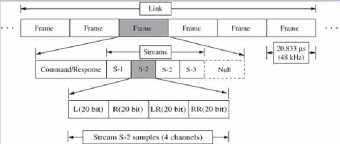
FIG. 4 The data frame composition used in the HD Audio specification,
defining how streams and channels are transferred on a link.
The link physically connects the controller and the codecs and conveys serial data between them. A time multiplexed link protocol supports various sampling frequencies and bit resolutions using isochronous (no flow control) transport with a fixed data transfer rate. Generally, all channels in a stream must have the same sampling frequency and bit resolution. Signals on the link are transmitted as a series of data packets called frames.
Each next frame occurs at 20.833 µs, corresponding to a 48-kHz sampling frequency, as shown in FIG. 4.
Each frame contains command information and as many stream sample blocks as needed. The total number of streams that can be supported is limited by the content of all the streams; unused capacity is filled with null data.
Frames occur at a fixed rate of 48 kHz so if a stream has a sampling frequency less than or more than 48 kHz, there is less than or more than one sample block in each frame (multiple blocks are transmitted at one time in the packet).
For example (see FIG. 4), some frames contain two sample blocks (S2) and some frames contain none. A single stream sample block can contain one sample for each of the multiple channels in the stream. For example (see FIG. 4), the illustrated S2 stream contains four channels (L, R, LR, and RR) and each channel has 20-bit samples; the stream thus uses 80 bits per sample block.
This stream has a 96-kHz sampling frequency since two sample blocks are conveyed per 20.833 µs frame.
Samples are packed in containers that are 8, 16, or 32 bits wide; the smallest container size which will fit the sample is used. For example, 24-bit samples are placed in 32-bit containers; samples are padded with zeros at the LSB to left-justify the sample in the container. A block contains sets of samples to be played at a point in time. A block size equals the container size multiplied by the number of channels; for example, a 24-bit, 3-channel, 96 kHz stream has a block size of 12 bytes. The same stream has a packet size of 24 bytes.
The specification allows considerable flexibility in system design and application. For example, a stereo analog signal might be input through an A/D converter for internal recording at 44.1 kHz and 16 bits; a 7.1-channel signal is output from a DVD disc at 96 kHz and 24 bits; a stereo 22-kHz, 16-bit signal is mixed into the front two channels of the 7.1-channel playback; a connected headset plays a communications stream from a net meeting-all functions occurring simultaneously. Also, the sequential order of processing can be specified; for example, a compressor/limiter can be placed before equalization, which will yield a different result from the reverse order.
Implementations of controllers and codecs are available from numerous companies. HD Audio is supported by a Universal Audio Architecture (UAA) class driver in Microsoft Windows XP SP3 and in Windows Vista; the AppleHDA driver is included in Mac OS X; Linux and other open operating systems support HD Audio. The HD Audio specification is available for download from the Intel Web site.
Windows DirectX API
The DOS programming environment provided simple and low-level access to functions, allowing full implementation of audio and video features. The Windows operating system added considerable complexity. The Windows Multimedia API allowed access to sound-card functionality. However, developers could not access peripherals directly-they were limited to whatever access functions Windows provided. For example, the Multimedia API provides no direct means to mix audio files.
Microsoft's DirectX API suite was designed overcome these kinds of limitations, and promote high-performance multimedia application development in Windows. DirectX APIs effectively provide real-time, low-level access to peripherals specifically used in intensive audio/video applications. DirectX APIs divide multimedia tasks into components including DirectSound, DirectSound3D, DirectMusic, DirectShow, Direct-Draw, Direct-Play, DirectInput, and DirectSetup.
DirectSound provides device-independent access to audio accelerator hardware. It provides functions for mixing audio files and controlling each file's volume, balance, and playback rate within the mix. This allows real-time mixing of audio streams as well as control over effects like panning.
DirectSound also provides low-latency playback so that sounds can be synchronized with other multimedia events.
The DirectSound3D API is an extension to DirectSound.
It is a set of functions that allow application programmers to add 3D audio effects to the audio content, imparting 3D sound over two speakers or headphones. The programmer can establish the 3D coordinates (x, y, z) of both the listener and sound source. It does not assume that the listener's central axis is in the center of the screen. The DirectSound3D API allows processing to be done natively on the local CPU, or on an expansion card's hardware DSP chip. In this way, the maximum number of applications can employ 3D audio, with appropriate degrees of processing overhead depending on the resources available.
DirectMusic is an extension to DirectX that provides wavetable synthesis with support for Downloadable Sounds (DLS), interactive music composition, and DLS and other authoring tools. DLS is an extension to the MIDI specification that defines a file format, device architecture, and API . DLS lets synthesizer developers add custom wavetables to the General MIDI sounds already stored in a sound card's ROM. Using system memory, DLS compatible devices can automatically download sounds from discs, the Internet, or other sources. DirectMusic also provides a music composition engine that lets developers specify the style and characteristics of a musical accompaniment, and also change these parameters in terms of tempo or voicing.
DirectShow (Version 5.2 and later) supports DVD decoders and DVD applications. It demultiplexes the MPEG-2 bitstream from the disc so that audio, video, sub picture and other decoding can be performed in real time with dedicated hardware or software means; in either case, the interface is the same. DirectShow supports aspects of DVD playback such as navigation, regional management, and exchange of CSS encrypted data.
Vendors provide DirectX drivers in addition to their standard Windows drivers. For example, a SoundBlaster DirectX driver provides access to fast SRAM on a Sound Blaster card, accelerating audio functionality. If a vendor does not supply a DirectX driver, DirectX provides an emulated driver. Applications may use this driver when audio acceleration hardware is not available. Although the emulated driver is slower, the developer retains access to the enhanced functionality. DirectX thus gives developers access to low-level hardware functions.
MMX
Companies have developed single-chip solutions to relieve the central processor of audio computation burdens.
However, simultaneously, processors have become more adept at performing multimedia calculations. For example, the Intel Multimedia Extensions (MMX) instruction set contained in Pentium processors is expressly designed to accelerate graphics, video, and audio signal processing.
Among other attributes, these 57 instructions allow a Pentium processor to simultaneously move and process eight bytes-seven more than previous Pentiums. In particular, this capability is called Single Instruction, Multiple Data (SIMD) and is useful for processing complex and multiple audio streams. MMX instructions also double the onboard L1 memory cache to 32 kbytes and provide other speed advantages. Using Intel's benchmarks, media software written for MMX will run 40 to 66% faster for some tasks. This efficiency allows faster execution and frees other system resources for still more sophisticated processing. Some Intel MMX processors will play DVD Video movies and decode their Dolby Digital soundtracks.
However, software-based processing on the host CPU has its limitations. If a 500-MHz processor devotes half its power to processing surround sound, wavetable synthesis, and video decoding, it effectively becomes a 250-MHz processor for other simultaneous applications.
File Formats
Interfaces such as AES3 convey digital audio data in real time. In other applications, transfer is not in real time (it can be faster or slower). Defined file formats are needed to transfer essence (content data such as audio) along with metadata (nonaudio data such as edit lists). In this way, for example, one creator or many collaborators can author projects with an efficient workflow. Moreover, essence can be transferred from one platform to another. In still other applications, file formats are specifically designed to allow streaming. In a multimedia environment, audio, video, and other data is intermingled.
Media content data such as audio, video, still pictures, graphics, and text is sometimes known as essence. Other related data can be considered as data describing data, and is called metadata. Metadata can hold parameters (such as sampling frequency, downmixing, and number of channels) that describe how to decode essence, can be used to search for essence, and can contain intellectual property information such as copyright and ownership needed to access essence. Metadata can also describe how to assemble different elements (this metadata is sometimes called a composition), and provides information on synchronization.
In some cases, audio data is stored as a raw data, headerless sound file that contains only amplitude samples.
However, in most cases, dedicated file formats are used to provide compatibility between computer platforms so that essence can be stored, then transmitted or otherwise moved to other systems, and be compatibly processed or replayed. In addition to audio (or video) data, many file formats contain an introductory header with metadata such as the file's sampling frequency, bit resolution, number of channels, and type of compression (if any), title, copyright, and other information. Some file formats also contain other metadata. For example, a file can contain an edit decision list with timecode and crossfade information, as well as equalization data. Macintosh files use a two-part structure with a data fork and resource fork; audio can be stored in either mode. Many software programs can read raw or coded files and convert them into other formats. Some popular file formats include WAV, AIFF, SDI I , QuickTime, JPEG, MPEG, and OMFI .