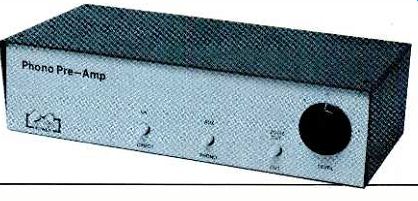
Features low noise and distortion and allows choice of cartridge
types
ALTHOUGH the phono preamp is often taken for granted, it has a critical and difficult job to perform. The preamp must boost signals on the order of a few millivolts or less to usable levels and, at the same time, compensate for the preemphasis applied to the recorded signals. A further task is to form an appropriate interface with the phono cartridge.
To perform adequately, a preamp must obviously have low noise and low distortion. The circuit must also offer accurate equalization and good input characteristics. To many circuit designers, these requirements are contradictory, resulting in designs in which one or more aspects of phono-preamplifier performance are compromised.
To circumvent some of these compromises, the design given here (Fig. 1) combines high-slew-rate BiFET op amps with discrete devices to form an "instrumentation amplifier" input stage. For fixed-coil pickups (moving magnet, moving-iron, and similar designs), with their relatively high impedance and signal levels, a low-noise, n-channel, JFET device offers noise performance equal to the best bipolar op-amp and an input impedance many times higher. Moving-coil pickups, which have low output impedances and levels, are coupled to ultra-low-noise pnp transistors for noise performance ten times better than the best bipolar op amp with comparable input impedance.
About the Circuit. With the exception of input devices and first-stage gain, the fixed-and moving-coil versions are almost identical (Fig. 2). The cartridge output is applied to the circuit's differential input stage and is amplified by 30 dB (60 dB in the MC version). Any undesired, common-mode signals pass through unamplified. The following stage, a differential-to-single-ended converter, adds the oppositely phased signal components and subtracts the common-mode components. This provides excellent rejection of unwanted signals.
The next stage, containing the playback equalization, is built around a precision deemphasis network. Preemphasis and complementary deemphasis are specified by the Recording Industries Association (RIAA) as a set of time constants. The lowest pole (the frequency at which rolloff begins) in playback response is given as 3180 µs, corresponding to 50 Hz (f = 1/ pi r T, where T is the time constant). Below 50 Hz, response is flat. Above this frequency, it falls at -6 dB /octave until the frequency corresponding to the next time constant, at 318 As (500 Hz). From 500 Hz to the frequency corresponding to the smallest time constant, 75 µs (2122 Hz), response is again flat, rolling off above 2122 Hz at-6 dB /octave. The original standard only specified response from 30 to 15,000 Hz, but it was recently extended to cover 20 to 20,000 Hz.
No problem is caused by the extended high-frequency response (most designers had been doing this all along), but maintaining flat response to 20 Hz limits the amount of attenuation in the 5-10-Hz warp region. To counter this, the International Electro-Technical Commission (IEC) has proposed a fourth time constant of 7950 µs (-3 dB at 20 Hz) be added to the RIAA playback standard (see "Build a Disco Mixer," POPULAR ELECTRONICS, September 1978). The -6-dB /octave rolloff starting at 20 Hz that would result attenuates warp signals and, to a slight extent, some of the program material as well (-1 dB at 40 Hz). To date, the proposal has not been accepted by the RIAA. This preamp adheres to the RIAA standard, but offers the IEC characteristic as a switch-selectable option.
To reduce warp and infrasonic signals and still maintain flat response down to 20 Hz, a 2-pole active high-pass filter, tuned to 10 Hz has been added. Below 10 Hz, the response rolls off at -12 dB/ octave. When the IEC time constant is switched in, the resulting response falls at -18 dB /octave below 10 Hz. A ± 1-dB trimmer built into the filter allows gain adjustment between the channels for proper balance.
Up to this point in the chain, the signal has been amplified 34 dB (at 1 kHz). An additional 16 dB of gain is subsequently provided for more than is necessary to meet the nominal RIAA gain standard (40 dB at 1 kHz). Some benefit accrues from the fact that this gain is adjustable. High-output cartridges are provided with 6 dB more of overload margin, and low-output cartridges can be amplified up to 10 dB more.
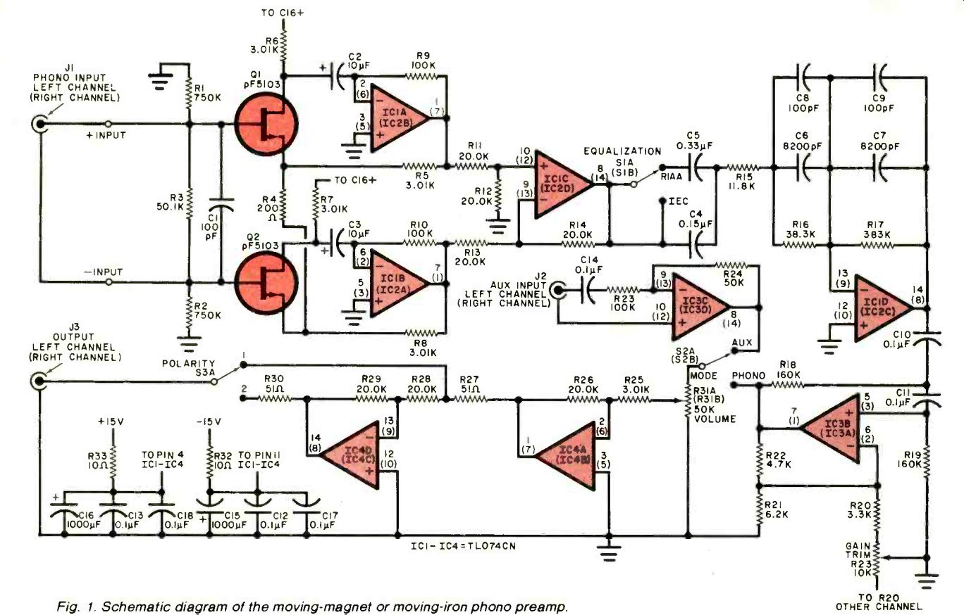
--------------Fig. 1. Schematic diagram of the moving-magnet or moving-iron phono preamp.
PARTS LIST
(Unless marked by a *, two of each component are required for a stereo preamp.)
C1,C8,C9-100-pF, 5% polystyrene capacitor
C2, C3--10-uF, 50-V radial-lead aluminum electrolytic capacitor
C19--Same as C2 and C3, but used in moving-coil preamp only.
C4--0.15-uF, 10% Mylar film capacitor
C5--0.33-µF, 10% Mylar film capacitor
C6, C7--8200-pF, 1% polystyrene capacitor
C10,C11,C14-0.1-uF, 5% Mylar film capacitor
C12 ,C13 ,C17 ,C18 --0.1-µF, 50-V disc ceramic capacitor
C 15 ,C 16 --1000-µF, 50-V radial-lead aluminum electrolytic capacitor
IC1 through IC4 --TL074CN quad Bi-FET operational amplifier
J1 , J2, J3-Phono jack (J1 must be an insulated jack)
Q1,Q2-Matched pair of pF5103 low-noise JFETs (moving-magnet /iron version of the project)
Q1,Q2--2SB7375 very-low-noise pnp silicon BJT (moving-coil version)
The following, unless otherwise specified, are 1/4-watt, 5% tolerance, carbon-film fixed resistors.
R1, R2--750 ohm
R3, R24--50.1 k-ohm, 1 /8-W, 1% metal-film
R4-200 0 R5,R6,R7,R8,R25-3.01 kit, lie-W, 1% metal-film
R9, R10-100 k-O
R35 -same as R9 and R10, but used in moving-coil preamp only
R11, R12, R13, R 14, R26, R28, R29--20.0 k-O, 1/8 -W, 1% metal-film
R15-11.8 k-O, 1/8-W, 1% metal-film
R16-38.3 k-O, 1/8-W, 1% metal-film
R17-383 k-O, 1 /8-W, 1% metal-film
R 18, R 19--160 kO
R20--3.3 k-O
R21--6.2 k-O
R22--4.7 k-O
R23 -10 k-O, pc-mount, screwdriver-adjust, linear-taper potentiometer
R27, R31--51 ohm
R31 -50 kO, B-volume-taper, panel-mount dual potentiometer
R32, R33--10 ohm
R34 -33 k-O
S1 , S2 , S3 -Pc-mount push /push dpdt switch
Misc.--Printed circuit board, standoffs, suitable metallic enclosure, hookup wire, shielded cable, suitable hardware, hum shield, solder. etc.
----------------
KIT AND PARTS AVAILABILITY
The following are available from Phoenix Systems, 91 Elm St., Manchester, CT 06040 (Tel: 203-643-4484): complete kit of parts, including enclosure but not the optional phono-cartridge input loading network, for the moving-magnet or moving-iron phono preamplifier, No. P-10-MM, for $99.00; complete kit of parts, including enclosure but not the optional phono-cartridge input loading network, for the moving-coil phono preamplifier, No. P10-MC, for $99.00.
Also available separately are: complete kit of parts for the optional phono-cartridge input loading network, No. P-10-IL, for $10.00; etched and drilled main printed-circuit board, No. P-10-PB, for $10.00; ST-4-28 power transformer, No. P-10-T, for $6.50; pair of matched, low-noise 2XpF5103 JFETs, No. P-10-FETS, for $5.00; etched and drilled power-supply printed-circuit board, No. P-10-PSB, for $4.00; dual 50,000-ohm, B-volume-taper potentiometer, No. P-10-DP for $2.50; TL074CN quad BiFET operational amplifier, No. P-10-OA, for $2.50; very-low-noise 2SB7375 pnp bipolar junction transistor, No. P-10-BJT, for $2.00; 8200-pF, 1% tolerance polystyrene capacitor, No. P-10-PCAP, for $1.00. If total is under $10.00, add $1.00 for handling. All prices postpaid in continental U.S. Connecticut residents, add 7 1/2 % tax.
--------------------
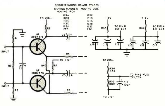
Fig. 2. Partial schematic shows changes required to convert the circuit of Fig. 1 into a moving-coil phono preamp.
CORRESPONDING OP-AMP STAGES MOVING MAGNET/ MOVING COIL
A high-level buffer and selector switch just before the volume control allow a line-level signal to be introduced past the phono equalization /gain stages.
This capability facilitates several possible interconnections with an existing system. The project can drive the power amp directly, with the existing control preamp feeding the AUX input. Alternatively, the project can drive a line-level input of the existing preamp, with the phono preamp's AUX input providing the existing preamplifier's line-level input that would otherwise be lost.
The final stage, a polarity inverter, is partly a concession to those who insist that the absolute polarity of musical waveforms be maintained and partly to facilitate experiments to test their hypothesis. As there is no way to ensure that the polarity of a signal radiated by a speaker matches that of the original acoustic signal, there is a 50/50 chance that the switch will be in the right position. You can try both positions and see if you hear a difference. (I have never found any.) The schematic of a power supply for the preamp is shown below in Fig. 3.
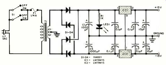
Fig. 3. Schematic diagram of the pwr supply that can be used to power either
the moving-magnet / iron or moving-coil phono preamp.
-----------------
POWER SUPPLY PARTS LIST
C1, C5--1000-µF, 35-V, radial-lead aluminum electrolytic capacitor
C2, C3, C6, C7--0.1-µF, 50-V disc ceramic capacitor
C4,C8-10-1.4.F, 25-V radial-lead aluminum electrolytic capacitor
D1 through D4-1 N4001 rectifier
F1--1/4-ampere fast-blow 3AG-type fuse with pigtail leads
IC 1--LM78M 15 + 15-V regulator
IC2-LM79M15-15-V regulator
LED 1--Light-emitting diode
R1-1000-ohm, 1/4-W, 50/0 fixed carbon-composition resistor
S1-Pc-mount, push/ push dpdt switch
T1-28-V, 250-mA, center-tapped pc-mount transformer (Signal Transformer No. ST-4-28 or equivalent)
Misc.
Printed circuit board, standoffs, line cord, strain relief, hookup wire, metal shield, solder, suitable hardware, etc.
--------------------
For a phono cartridge to deliver the performance its designer intended, it should be loaded with the proper combination of resistance and capacitance.
The preferred method is to Solder resistors and capacitors of appropriate values directly across the preamp inputs, but this makes changing loading to suit different cartridges a major chore. The task is simplified by an optional, switchable input load (Fig. 4) that can be adjusted in 25-pF steps. The DIP switch specified has gold /gold contacts. (It is a good idea to exercise the switch once every year or two.) To determine the correct load capacitance, refer to the manufacturer's literature. Subtract from this the fixed capacitances already present in your system, including those of the tonearm and hookup cables. That of typical shielded cable is 25 to 30 pF / ft. Low-capacitance (CD-4) cable has somewhat less. Next, add the input capacitance of the preamp. (The fixed-coil version has about 110 to 115 pF nominal.) If the total fixed capacitance is close to what is required, you can make up small differences by substituting cables or, if this isn't enough, by changing the value of C1. But don't eliminate C1 entirely.
NOTE: ALL CAPACITORS ARE 5% TOLERANCE POLYSTYRENE COMPONENTS.
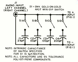
Fig. 4. Schematic diagram of the optional, switchable input load.
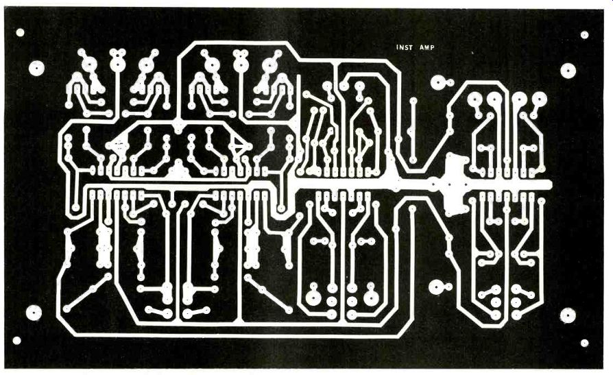
Fig. 5. Full-size etching and drilling guide for the project's main pc board.
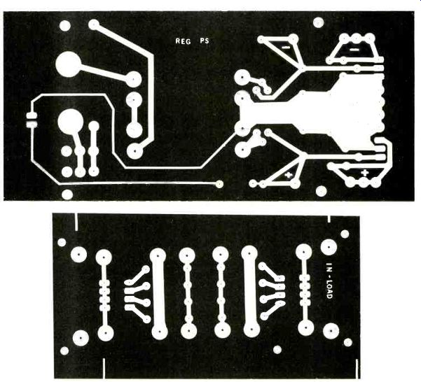
Fig. 6. Full-size etching and drilling guide for the power supply's printed circuit board.; Fig. 7. Etching and drilling guide for the optional input load.
Once you have calculated the system's total fixed capacitance, record it to save trouble in the future. Finally, subtract the fixed capacitance from the required capacitance and, if necessary, switch in enough to make up the difference. Note, however, that the loading network is intended for fixed-coil cartridges only.
Construction. It is preferable to use a pc board (Figs. 5, 6, and 7). Component layout (Figs. 8 to 11) is similar for the moving-coil and fixed-coil configurations, but there are changes in power-supply connections and IC, transistor, and polarized-capacitor orientation.
Rather than design two different pc boards, we can take advantage of the symmetry of the TL074 op amps and rotate them 180 degrees when reversing the power supplies. Take care to follow the appropriate parts-placement diagram closely. Note that Q1 and Q2 are JFETs in the fixed-coil circuit and BJTs in the moving-coil preamp. Be sure to use a hum shield on the end of the main board next to the power supply board as shown in the photo. The shield can be made of a piece of 1/32-inch aluminum stock 21/4" x 4" with one side folded and drilled for mounting in existing holes on the board.
JFET and BiFET op amps are not as sensitive to static discharge as MOS devices. However, recent research has shown that all components can be damaged by static so reasonable caution should be exercised. When assembling the optional input-load board, be sure to have capacitor markings facing up. You can then read them easily when changing loading. The banded end of a polystyrene capacitor denotes its outside foil plate and should be connected to ground to suppress hum.
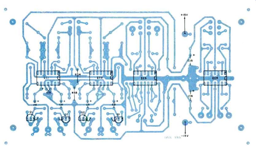
Fig. 8. Component placement guide for the main printed-circuit board.
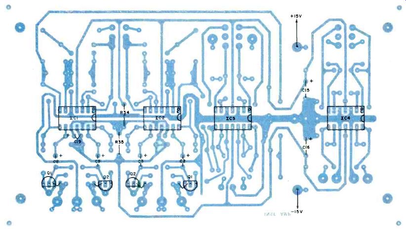
Fig. 9. Component placement guide reflects changes with respect to Fig. 8. that must be made for assembly of a moving-coil phono preamp.
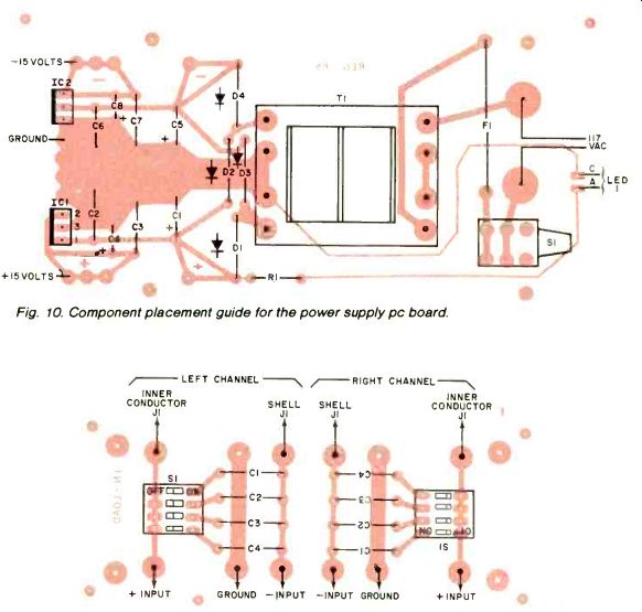
Fig. 10. Component placement guide for the power supply pc board. Fig. 11. Component placement guide for the optional, adjustable capacitive phono-cartridge loading network.
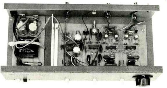
Photograph of the author's prototype reveals construction details and the presence of a metal shield between the main and power-supply pc boards.
The input-load board should be mounted inside the preamp's metallic enclosure near the phono input jacks.
Use insulated jacks or, better yet, hardwire quality phono cables directly to the board. Be sure to include a ground terminal connected to both the metallic enclosure and the ground bus. The turntable ground lead will be attached to this terminal.
Use. Connection of a phono preamp into an audio system is straightforward and will not be reviewed here. Remember, though, to balance the right and left outputs of the cartridge by adjusting R23 for equal levels from both channels while playing a monophonic disc. If you include the input load board, take the time to adjust it as well. Having completed these steps, you can enjoy your system secure in the knowledge that your phono preamp is close to the state of the art.
Also see:
Phoenix Systems P-10-MM Phono Preamp (May 1983)
New Tests for Preamplifiers (by Tomlinson Holman) (Feb. 1977)
Birth of a Spec? PHONO CARTRIDGE NOISE (March 1977)
= = = =