9-1. Relative Importance of TV Application
Although sweep generators have many applications, the largest number of them now in use are designed for, and used for, tv receiver response analysis. It is therefore well that we review here some of the factors involved in preparing for sweep analysis of the response curve of a tv receiver. Actual details of receiver adjustment are beyond the scope of this book, but the different measures leading up to it are of importance in connection with any study of the sweep generator itself.
The nature of the process is such that, if proper preparation is not made, and proper equipment is not available, it is very difficult to obtain the desired results.
9-2. The Sweep Generator
The requirements and characteristics of the sweep generator have been discussed to some extent earlier in this book. The center frequency of the sweep output should be adjustable to the receiver's i-f range, and to the frequency range of any desired channel. This adjustment may be either by continuous dial variation or by selection of the desired ranges by means of a switch, with the center frequency of each range fixed.
The sweep generator output voltage should be adequate, at least 10,000 microvolts, with 100,000 microvolts desirable. It is also desirable that a high output jack be provided, from which 1 volt or more of signal is available, although this is not necessary. There should be a continuous attenuator so that the amplitude of the signal can be adjusted to avoid overloading and to provide a response image of useful size. The generator should also preferably have a phase adjustment, although this is not necessary if phase adjustment is provided on the oscilloscope.
Blanking of the generator signal is another provision which is not absolutely necessary but is desirable and helpful.
The sweep width should be adjustable through a reasonable range.
The maximum width required for tv response characteristics is from 10 to 15 mhz. This should be controllable down to several hundred kilo cycles; the minimum width is useful in observing sound section response, and aligning the sound i-f stages and discriminator.
9-3. Sweep Generator Controls and Connections
Although the characteristics and features of sweep generators have been previously discussed, it is well before proceeding with alignment or response checking to become completely familiar with all the controls and connections involved, if this has not been done before. Let us there fore review briefly these controls and connections.
CENTER FREQUENCY CONTROL: This is a dial or switch, or combination of both, which adjusts the center radio frequency about which the carrier frequency is swept. Frequently it is a dial, similar to those used in a-m signal generators or receivers. Because the center frequency must be adjustable over a wide range for coverage of intermediate frequencies and all r-f channels, more than one tuning range is usually provided. There is then a band selector switch, which determines which of the several dial scales is used. In some cases, a selector switch is used to select the desired coverage, in which case the center frequency is preset at the proper value. In most generators, the dial reading gives true output frequency (within the tolerance of the calibration). however, sometimes the fixed frequency of the swept oscillator must be added to or subtracted from the indicated dial frequency. The latter is rare, but must be considered.
SWEEP WIDTH: This is ordinarily simply a knob, with a pointer or spot to indicate relative position. Sometimes there is a scale of from 1 to 10 or some other range. This scale is usually an arbitrary one, and does not indicate sweep width in frequency units. Sweep width must be checked numerically by use of markers on the pattern when the latter is obtained. The sweep width control is used to adjust the width so that the complete response curve is taken in, and not for any exact numerical sweep width.
ATTENUATOR: In sweep generators, there is usually only one attenuator, and that is the continuously variable type. This is used to keep the output amplitude down to prevent overloading, and to provide a reasonable image size, in line with the gain of the oscilloscope.
BLANKING: This controls whether or not the sweep generator oscillator is cut off during the return trace of the oscilloscope. It is ordinarily just an on-off switch which either provides blanking or not. As has been previously explained, blanking provides a horizontal base line under the response curve, because there is zero vertical deflection during the return trace.
PHASE: This is a continuously variable knob control which changes the phase of the a-c voltage fed to the oscilloscope horizontal circuit compared to that of the voltage used to sweep the generator frequency.
With this control, the response curves traced on the forward and reverse traces are adjusted to coincide, instead of being separated horizontally on the oscilloscope screen. Of course, if the blanking is on, the phasing adjustment merely moves the single response curve along the horizontal base line.
OUTPUT JACKS: Some sweep generators have one output jack; others have two. When two are used, one is usually for i-f output, while the other is used for r-f output for front-end injection. If the sweep generator is equipped with internal marker oscillators, extra jacks will be provided for marker output. In a few cases, a-f output and occasionally linearity pattern generator output is provided in the same unit. There will then be either a separate output jack for each of these output signals, or else a single output jack for several, with provisions on a selector switch to choose which one is used.
The jacks used are most frequently of the microphone connector type illustrated in Fig. 9-1 (A), and the leads used must have the mating connector at the generator end. Sometimes phone jacks are used, (Fig. 9-1 (B) and (C)), with phone plugs or tips on the leads. In any case, careful shielding must be maintained, and the proper leads must always be used.
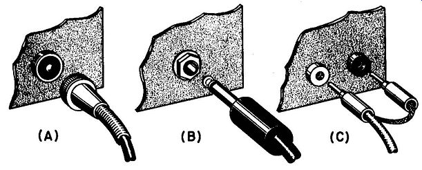
Fig. 9-1 . Types of connectors commonly used for signal generator output.
(A) Microphone connector type, (B) phone, plug type, and (C) phone-tip type.
Oscilloscope CONNECTION: This is most frequently a binding post.
From it a wire must be run to the horizontal amplifier input of the oscilloscope, so the horizontal deflection of the scope beam is synchronized with the sweep frequency variation.
GROUND CONNECTION: This is also ordinarily a binding post. or screw connection. The importance of good grounding has been discussed in Section 7. From the grounding connection, a large short lead should be connected as directly as possible to ground. Some generators have metal grounding feet. If a ground plate is used (as is very desirable) these bare metal feet contact the ground plate and automatically provide a direct ground connection.
9-4. Signal Generator leads
There may be several different leads provided with the sweep generator; the purpose of each should be reviewed. Normally, there may be two leads: one for single-ended output, for front ends of receivers using coaxial line input and for i-f sections; and one for balanced output, for connecting to balanced front end input circuits. The methods used for terminating these leads and coupling to the impedances involved are discussed in Section 7.
9-5. Marker Generator
At least one marker generator or marking device is necessary for proper alignment or response checking. As previously explained, the marker indicates response width, and the locations of different parts of the response curve in the frequency spectrum.
One way of providing marking is by means of a separate oscillator which has its frequency adjusted to the frequency at which marking is desired. This signal is injected along with the sweep signal, and beats against the latter at the marker frequencies to produce pips. The other marking method is by means of absorption markers, which are tuned circuits resonant at the marker frequencies which produce discontinuities at the desired points. These methods have been discussed earlier in this book. Many sweep generators have absorption-type markers or marker generators, or both, self-contained. If a marker generator is provided, there is also usually a marker frequency dial adjustment and an attenuator. There may be an extra switch for selecting the marker frequency tuning ranges. Sometimes provision is made for use of a crystal oscillator as a marker generator, and an external crystal socket may be provided so any crystal of desired frequency may be used.
9-6. Oscilloscope
The oscilloscope used for visual alignment and response analysis must meet certain minimum requirements. The screen size should be great enough to permit comfortable viewing; a 3 inch diameter is usually considered a minimum, and at least 5 inches is desirable, to allow easy identification of parts of the response curve and markers. The vertical deflection amplifier should have good response at 60 hz, so as to respond readily to the sweep cycles, and a reasonably good sensitivity to provide usable deflection when low-output stages of a receiver are being tested. The oscilloscope must have an external connection to the horizontal deflection amplifier, so the sync voltage from the sweep generator can be applied. The vertical and horizontal gain should be adjust able, as is true in practically all oscilloscopes.
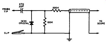
Fig. 9-2. Typical circuit for crystal probe used to rectify r.f. from receiver
stages before application to oscilloscope.
It is desirable also that the oscilloscope be provided with a detector probe, which connects to the vertical input circuit. This probe circuit rectifies any r-f signal applied to it from the receiver, passing on to the vertical amplifier a d-c voltage proportional to the strength of the r-f signal. This detector probe is not necessary when the receiver output is taken from the mixer or second detector for i-f amplifier and tuner response checking. However, when the output of one or two i-f stages is to be observed, some method of detection is usually necessary, and the probe is used. A detector is also necessary when the response of the video amplifier section is to be observed by sweep methods. Video-frequency voltages (0-4 mhz) are rectified at the output circuit (usually the grid of the picture tube) and applied to the vertical deflection circuit of the oscilloscope. A typical detector probe circuit is shown in Fig. 9-2.
9-7. Bench and Ground Plate
Sweep analysis of a tv receiver is not a simple operation; however, it can be made unnecessarily complicated if not enough room is allowed for the operation. The bench on which the equipment is set up should be of sufficient size to hold all units with extra room to spare.
The bench should preferably be equipped with a good ground plate, upon which all equipment can be placed, as explained in Section 7.
This will go a long way toward avoiding grounding troubles. Of course, there should be provision for a good ground connection to the bench, and convenient ground connection points should be available so that all units may be grounded. If strong interfering signals are present, it may be necessary to do additional shielding, even to use a shielded room.
One caution should be exercised when transformerless power supplies (such as are found in many tv receivers, and in some signal generators and other equipment) are employed and a ground plate is being used.
In these supplies, one terminal of the power source is usually connected to the chassis. This means that if the power plug is placed in the receptacle in such a way that the "hot" (ungrounded) side of the power line is the one connected to the chassis, this chassis can become charged with the full power-line voltage with respect to true ground (such as a water pipe). This could easily be a hazard to the operator, and may in some cases burn out signal generator attenuators, receiver antenna coils, or line fuses.
It is strongly recommended that the equipment used include an isolation transformer for the power line. This transformer is a 1 to 1 ratio power transformer, whose function is to provide a power source for the receiver and generator and any other power-operated equipment.
The advantage is that the power source thus provided has neither terminal grounded.
Isolating transformers are available in various ratings from 100 to 2,000 watts. About 1,000 watts ought to be sufficient for most tv alignment set-ups. Some isolating transformers have several taps on the primary winding, allowing some compensation for variation in line voltage.
9-8. Coupler for Mixer Tube
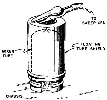
Fig. 9-3. Using a tube shield for coupling to the mixer tube.
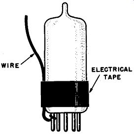
Fig. 9-4. Another method of connecting a sweep generator to the mixer lube.
When the i-f amplifier of the tv receiver is being aligned or checked as a unit, the output of the sweep generator is usually applied to the mixer tube. In order that the receiver circuits be disturbed as little as possible, the coupling should be very loose. One method for accomplishing this coupling is by wrapping an insulated wire around the mixer tube envelope, as was shown in Fig. 7-1 (B). The "hot" lead from the signal generator is then connected to one end of this wire and the capacitance between this loop of wire and the tube elements provides the desired coupling into the i-f amplifier section.
Another method of coupling to the mixer tube, recommended by many receiver manufacturers, is that shown in Fig. 9-3. The mixer tube shield is simply raised slightly so that it no longer contacts the chassis.
The generator hot lead can then be connected to the ungrounded shield.
The capacitance between the shield and the tube elements in this case provides the coupling. Some technicians prepare a special mixer tube shield by putting tape on the bottom edge of the shield where it would normally contact the chassis. This permits the shield to be pushed well down on the tube hut still not be grounded.
Still another method recommended by some manufacturers is shown in Fig. 9-4. Here a short lead is connected to the mixer grid pin. The lead is then taped to the tube envelope. In cases where the manufacturer recommends the disabling of the local oscillator, a special mixer-oscillator tube is prepared by cutting off the plate pin of the oscillator section.
9-9. Alignment Tools
The technician will find that he must keep on hand a variety of alignment tools to be properly equipped for the adjustments in various receivers. In addition to ordinary average-sized screwdriver types, he will require very narrow, long types suitable for insertion into the front of tuner units. The tools are preferably of the insulated type with metal only on the tip, or blade, of the instrument. Metal tools may introduce too much capacitance and cause the adjustments to be different when the tool is on the adjusting screw, even though the latter is not directly connected into the circuit. It is well to have tools available for adjustment of iron-dust cores in which the blade of the tool is directly inserted into the core itself, which is slotted. The tool for this purpose prefer ably has a nonmetallic blade and should be a good fit in the slot, or else breakage of the cores may result at the slot, making further adjustment difficult or impossible.
9-10. Bias Battery
It is difficult, if not impossible, to obtain a proper response curve for many receivers if the age circuit voltages are not what they would normally be under ordinary conditions of reception. When a sweep generator is feeding its output into the receiver during alignment, normal age voltages are not developed, therefore the operation of the receiver is not the same as it would be with an ordinary input signal. For this reason, most receiver manufacturers recommend the use of a bias battery, which is connected into the circuit to provide a steady bias during alignment or checking procedures. This bias should be of similar value to the normally developed agc voltage.
The voltages required vary from around 1½ to about 8 volts, depending both upon the receiver to be aligned and the location in which the adjustments are being made. Very appropriate for such requirements is the ordinary type of C-battery. This battery is tapped at every 1 ½ volts up to a total of 7 ½ volts. By using clip leads to the battery, the technician can easily select the desired bias for any given operation.
This battery should be in reasonably good condition, and the checks ordinarily used in checking radio receiver batteries are appropriate.
Some manufacturers recommend the use of a potentiometer (1,000 to 2,000 ohms) across the C-battery in order that an exact adjustment of the value of the age voltage may be made.
9-11. Importance of Manufacturer's Data
We have now outlined the equipment which must be assembled before we are ready to proceed with alignment or response checking of a tv receiver. We have discussed this equipment from a general stand point, so the technician can become familiar with what he is likely to need in all cases.
But before sweep alignment is undertaken, it is important that he have available all the manufacturer's data possible on just how the alignment of that particular model should be accomplished. Since the manufacturer has developed and manufactured the receiver, he is the best authority as to the proper procedure in aligning it. The technician should, therefore, obtain from the manufacturer, or from a publisher of alignment and servicing information, the most complete data avail able.
When such data has been obtained, it should be studied before the operation starts. It is certainly very much easier to determine first, on paper, the locations of the various adjustments of the receiver chassis, and also the locations of connections provided for equipment, than to have to hunt for these later after alignment procedure has supposedly started. Most modern tv receivers have been designed to include connection points by which the signal generator can be connected and the oscilloscope vertical lead applied, at the top of the chassis, for the convenience of the technician. Location of all such points is greatly to the technician's advantage in minimizing time and trouble. It is certainly desirable that the step-by-step recommended procedure be read through before alignment starts.
The manufacturer's data will also often provide such information as how much bias to use for each test, whether stage-by-stage checking is necessary (as in stagger-tuned systems), about how much generator voltage to use, as well as much additional useful information concerning the actual alignment technique. The manufacturer is, of course, also the final authority on the details of the response curve to be aimed at, specifying the exact frequencies to be marked, and how much tolerance is allowable.
9-12. Laying Out the Equipment
The exact placement and arrangement of the equipment is in each case necessarily a matter for which the technician must use his judgment. The factors influencing the placement are:
1. The availability of good ground connections and the size and location of the ground plate.
2. The availability of power-source connections, to supply the sweep generator, marker generator, oscilloscope, and receiver. Naturally, if these are not consistent with good grounding and conveniences in the functional operations of alignment, they should be made so.
3. Adequate spacing between sweep generator and receiver. This spacing is preferably as great as the lead from the generator will allow to reduce leakage and spurious output effects from the generator to a minimum. However, never attempt to extend the length of the generator leads. These are designed to operate as they are with the generator, and if made longer may interfere with operation, as explained in Section 7.
If both the receiver and the generator are well grounded, and the spacing between them is as great as the leads will comfortably allow, there will seldom be any trouble with leakage or spurious effects with most pieces of test equipment.
4. Completeness of grounding and shielding. Make certain that the shields of all leads, the cabinets of all units, and all other shielding is grounded as directly as possible to a common point. As was pointed out in Section 7, connection of all units separately to a common ground point is the best, in preference to grounding of any unit through another unit chassis.
5. Order of signal progress through the equipment. Most technicians find it simpler to arrange the units in order of the signal travel through them, as it is orderly and less confusing in following what is happening. Thus, the sweep and marker generators would be placed at the left, the receiver in the middle, and the oscilloscope to the right.
Of course, this is a relatively minor consideration, and should not interfere with such things as good grounding and proper inter-unit connections.
A typical complete set-up for sweep alignment of a tv receiver is shown in Fig. 9-5.
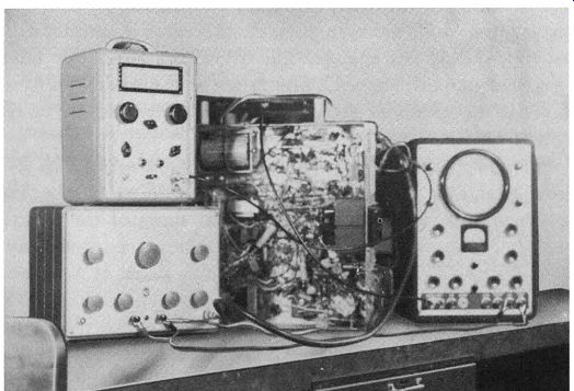
Fig. 9-5. A typical bench set-up ready for sweep alignment or analysis of
a tv receiver.
9-13. Warm-up
The importance of signal generator warm-up before use was explained and discussed in Section 5. Before such an operation as sweep alignment it is well to allow a full half hour of warm-up before starting actual alignment operations. Warm-up is important not only for the sweep and marker generators, but also for the receiver and the oscilloscope. In short, it is best that all equipment which uses appreciable power from the power lines be turned on ahead of time, so that all heating effects will be stabilized as much as possible by the time alignment operations start.
9-14. Marker Injection
The marker signal may be injected in a number of different ways.
General recommendations are made in service literature, but all of them do not prove equally satisfactory with all kinds of marker generators.
Experience has taught most service technicians that injection of the marker signal without affecting the response of the system being checked is sometimes difficult to achieve. Yet the marker signal must be applied.
The primary requirement for marker signal injection is that the marker must be easily seen on a scope; yet the signal level should not be so high as to overload the receiver and affect the response curve. With present-day methods of injection, this is not always possible, although the degree of change in response curve need not be excessive. Some change will be encountered in virtually every receiver i-f system. If the change does not influence the shape of the response curve, it is not harmful.
Whatever normal peaks and dips are visible in the response curve prior to the application of the marker signal should be present after the marker is applied, and, more important, the relative amplitude of the peaks and dips should not change. The overall height of the curve may change, but the shape must not. The latter is the most important condition, for it is the means of determining the relative degree of response of the system to different frequencies.
One common method of marker injection is shown in Fig. 9-6. Here the marker generator output lead is being coupled to the hot lead from the sweep generator by winding several turns of the marker generator output cable around the hot lead of the sweep generator cable near the feed point or by winding one or two turns of insulated wire around the sweep generator hot lead and connecting the hot lead of the marker generator to one end of this wire. Another way of accomplishing such coupling is by clipping the hot lead from the marker generator to the insulation around the hot lead from the sweep generator. Do not force the clip through the insulation of the sweep generator output lead.
--------------
This material was excerpted from TELL-A-FAULT, published by John F. Rider Publisher, Inc.
----------------
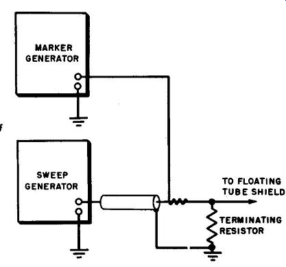
Fig. 9-6. A common method of injecting a marker signal.
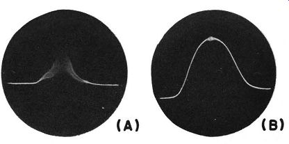
Fig. 9-7. A response curve with excessive marker signal is shown at (A). The
proper display appears at (B).
A second method of feeding the marker signal consists of connecting the marker generator output leads directly in parallel with the sweep generator output leads. The method is not too satisfactory. More frequently than not, it loads down the receiver because the level of the marker signal fed into the receiver is too high even when the marker output attenuator is reduced to zero. In addition, there is no isolation of the two pieces of test equipment. The appearance of a response curve that is "knocked down" because of excessive signal from the marker source is shown in Fig. 9-7 (A). Compare this with the curve shown at (B) where the proper marker display exists. With this method it is a common practice to insert a small capacitor between the marker generator lead and the sweep generator lead. The size of this capacitor is not critical, however it must be as small as possible in order to provide adequate isolation while, at the same time, allowing passage of the marker signal. When this is done, such a method of marker injection may prove to be satisfactory.
A third method may appear to be a strange way of feeding a marker signal into a receiver, but it usually functions satisfactorily in every respect. Both ground and hot leads of the marker generator output cable are connected to the chassis (see Fig. 9-8). The ground lead from the sweep generator is joined to the ground lead from the marker generator.
The separation between the ground and hot leads from the marker generator is between 3 and 4 inches. Control of the marker signal level is by means of the marker output attenuator, as is usual, and normal action is obtained with utmost ease. With this arrangement the marker signal is actually produced by means of a ground loop, formed by the portion of the chassis shown, and the leads.
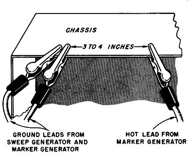
Fig. 9-8. Marker injection by means of a ground loop.
In addition to the foregoing methods, marker injection may also be accomplished by connecting the hot lead of the marker generator through a small capacitor (say 2 to 10 µ.µ.f) to various points in the tv i-f circuitry.
Some such connection points which have proven satisfactory for marker injection are as follows: screen-grid circuits of the i-f amplifiers, various points along the age bus, and the B-plus end of the plate windings of i-f stages.
9-15. Checking Generator Characteristics
It is assumed that the technician will have investigated, and become quite familiar with, his sweep and marker generators before he starts his alignment of the receiver. Most checks of the performance of generators themselves can be most correctly classed as maintenance, and are therefore discussed in Section 11. If such maintenance is attended to regularly, the technician will know the response of his generator output, sweep width as compared to that specified, linearity of sweep, and other characteristics. Other items of equipment should also have been carefully checked. For example, crystal detector probes should be checked for response, and it should be known that the detector response is good over the desired sweep ranges to be used, so, that where it is not good, it can be properly corrected for.
However, even though these operations are really maintenance, there are a few routine tests which can be performed each time alignment is to be done. If the maintenance measures discussed in Section 11 are taken, certain parts of the checks described there will be gleaned as checks which can be used in each alignment operation as a double-check and insurance against poor results due to some defect which may have crept into the equipment.

Fig. 9-9. When the phasing is misadjusted, with, blanking off, two response
curves appear. Adjustment of the phasing brings the curves together to coincide.
Several routine checks can be made after the units are all operating and a response curve has been obtained. Leave the blanking control off at first and adjust the response curve for proper phasing with either the sweep generator or the oscilloscope phasing control. With blanking off, improper phasing will be indicated by the presence of two response curves, horizontally displaced from each other, as explained in Section 4.
A typical case of improper phasing is shown in Fig. 9-9. When the phasing has been adjusted, the two curves, one from the forward trace and the other from the return trace, coincide, as shown in Fig. 9-9 (C). Next, the sweep width can be adjusted for proper inclusion of the complete response curve and the sweep width checked as explained in Section 11. It is also desirable to check the frequency calibration of the marker generator or generators. This should be done periodically during the alignment process, but of course is especially important just before it starts. The frequency checks can be made by use of a calibrator or a heterodyne frequency meter, which is about the same in operation as a crystal calibrator. The heterodyne frequency meter may not have a crystal reference oscillator, but is designed to be sufficiently stable in itself to maintain a very accurate calibration.
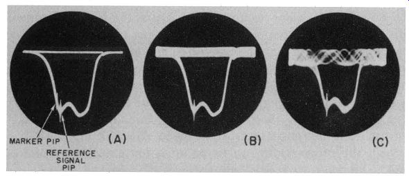
Fig. 9-10. The frequency calibration of the marker generator can be checked
against a reference signal whose exact frequency is known. The checking can
be done by visual means as shown here. Each signal is indicated by a pip on
the receiver response curve; the marker pip is then tuned by adjustment of
the marker oscillator until the pips coincide and the marker dial checked against
the reference frequency.
If a crystal calibrator is not available, a separate crystal oscillator or other accurate known source of r-f signal can be fed into the receiver to be aligned along with both the sweep generator signal and the marker whose calibration is to be checked. With the response curve of the receiver present on the oscilloscope screen, marker pips can be obtained from both the marker generator and the reference signal of accurate frequency (providing, of course, they are within the pass band of the receiver). A typical response curve with two marker pips such as might result in this case is shown in Fig. 9-10 (A). The marker oscillator is then tuned until the marker pip moves along the receiver response curve and finally coincides with the reference-frequency pip. As the two frequencies come together, they produce a beat signal (see part (B) of Fig. 9-10), gradually decreasing in frequency (see part (C) o{ the figure). The adjustment of the marker frequency at which the frequencies are zero beat (exactly coincide) can easily be recognized. The calibration of the marker oscillator can then be checked against the known frequency of the reference signal.
The special advantage of such a check is that it can be done with all units connected and ready for alignment or response checking, and disconnecting and reconnecting of units is not necessary. If the reference frequency is one useful also in the alignment procedure, it can be used as an additional marker. The reference signal can be obtained from a crystal oscillator fundamental or harmonic, or from an external frequency standard.
9-16. Common Setting-Up Troubles and Their Solution
Until the beginner at sweep alignment has become thoroughly familiar with the operation and his particular set-up, he may run into difficulties in obtaining a good response curve to work with in subsequent adjustments. Although a discussion of the manner in which receiver response is adjusted in alignment is beyond the scope of this book, we are concerned here with the preliminary setting up and adjusting of the sweep generator and associated equipment in preparation for alignment. No book could possibly cover all the types of troubles which may arise in the development of a response curve. However, the following list is a practical set of examples as to what might happen most frequently, and what to watch out for in first obtaining the response characteristic on the oscilloscope screen.
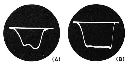
Fig. 9-11. Typical good receiver response curves.
First, the technician should be familiar with the kind of response characteristic he should have. Since the curve shape varies from one receiver to another, as well as according to how much out of alignment the receiver has become, there can be no set indication of curve shape in general. The technician will develop a "feel" for recognizing whether the curve he obtains is truly representative of the actual response of the receiver. This will be developed when the technician knows and has confidence in what he is doing. When the curve is correct, it should be stable and unaffected by motion of the body around the receiver, and should not change shape as the attenuator is adjusted up to the receiver overload point. Typical good receiver response curves arc shown in Fig. 9-11.
--------------- 2. For a complete discussion of curve shaping in tv alignment see "TV Sweep Alignment Techniques" by Art Liebscher, published by John F. Rider Publisher, Inc., New York, N. Y.
----------------------
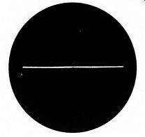
Fig. 9-12. No response indication.
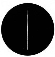
Fig. 9-13. No sweep indication.
No response indication at all (see Fig. 9-12). In this case, there must be a discontinuity between the sweep generator output circuit and the oscilloscope vertical deflection plates. A circuit defect anywhere along the line can cause this. First, make sure the sweep generator is putting out r-f voltage. This can be done by listening in on the sound section of the receiver to see if there is evidence of the sweep signal coming through, or by applying the sweep signal to any a-m receiver which tunes within the range. In the latter case, the presence of the signal may be more easily detected if the sweep width is reduced to a minimum. On a selective a-m receiver, the signal will be noted as a buzzing raspy sound, similar to a hum, rather than a fixed carrier, unless the sweep width can be reduced to zero. A VTVM with an r-f probe may also be used to determine whether or not there is output. If the generator is putting out voltage, it may be that the receiver has a defect which does not allow the signal to get through it. This should be traced by ordinary troubleshooting methods. Of course, the connections between the generator and the receiver should also be checked. If the receiver and generator are both alright, then check the oscilloscope. For most ordinary settings of vertical gain, the oscilloscope should show vertical deflection when the vertical circuit lead is removed from the receiver and grasped with the hand. When any discontinuities in the path of the signal from the generator to the oscilloscope vertical plates have been removed, some kind of vertical deflection and curve should be obtained.
No horizontal deflection (see Fig. 9-13). In this case, set the oscilloscope for internal horizontal deflection instead of external. If there is no change, there must be trouble in the oscilloscope horizontal deflection circuit. If the horizontal deflection is obtained by this adjustment, then the sync voltage from the sweep generator is not getting through.
Check the sync output of the generator with an a-c voltmeter and check the lead which connects it to the oscilloscope.
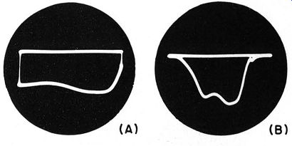
Fig. 9-14. Insufficient sweep width indication.
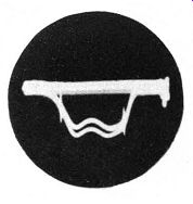
Fig. 9-15. Erratic response indication.
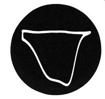
Fig. 9-16. Response curve with 120-hz pick-up distortion on baseline.
Two separated horizontal lines whose spacing can be adjusted by varying generator attenuator (see Fig. 9-14 (A)). This is caused by insufficient sweep width to show the whole response curve. Two horizontal lines will be present this way only when there is blanking in the sweep generator; one line represents the base line, the other the top of the response curve. When the sweep width of the generator is increased, the two lines will approach each other and touch at the edges, restoring the correct pattern as shown in part (B) of the figure.
Rough base line and erratic response (see Fig. 9-15). This can be caused by some extra interfering signal, particularly an overly strong marker signal. Removal of the interference, possibly by better shielding and grounding, or proper adjustment of the marker attenuator, or reduction of the marker generator coupling to the receiver should eliminate this effect.
Non- linear base line, 120-hz ripple (see Fig. 9-16). This is usually due to improper or imperfect grounding connections, or a-c pickup on the leads. Sometimes if the signal generator lead connection to the chassis of the receiver is made at some distance from the tuner input circuit, such pick-up results.
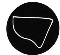
Fig. 9-17. Distortion due to oscillator tube removal.
Distortion of the r-f response curve due to oscillator removal (see Fig. 9-17). This is what may result when the oscillator tube is removed during or for r-f response checking. The oscillator tube should be kept in its socket for front-end alignment, or else the mixer tube receives improper bias and circuit capacitances are not correct. Of course, other troubles in the tuner section can also cause such distortion.
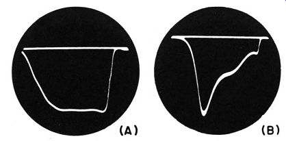
Fig. 9-18. Distortion due to over loading.
Distortion from overloading (see Fig. 9-18). This may not appear as distortion at all at first. The curve at (A) is obtained with overloading, which causes the apparent flatness of response. However, when the sweep generator attenuator is adjusted to reduce the sweep signal input to the receiver, the response may actually turn out to be as shown at (B), as in the actual case illustrated here. This emphasizes that the ·sweep generator output attenuator should always be varied and adjusted until it is clear that overloading is not affecting the response curve shape.
Adjustment of the attenuator from zero output up to the overload point should vary the height of the response curve but should not affect its shape.
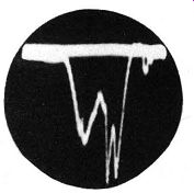
Fig. 9-19. Distortion due to presence of strong local signal.
Curve distortion plus fuzziness (see Fig. 9-19). Try changing the set ting of the channel selector; if the response changes, the distortion is probably due to the presence of the signal of a strong local station on the channel to which the receiver is set. The setting of the channel switch can have a marked effect on the response curve distortion. Manufacturers of receivers usually recommend just how the selector switch should be set during i-f alignment; this recommended setting is usually for one of the highest frequency channels (11, 12, or 13) on which there is no local station.
Base line tilt and distortion (see Fig. 9-20). This can result from reflections from the i-f amplifier circuits when the tuner section is being aligned. If this is the cause, it can be eliminated by removal of the first i-f tube from its socket.

Fig. 9-20. Distortion due to i-f amplifier reflections.