|
|
__6.3 Solving Interface Problems
__6.3.1 Ground Isolators
A device called a ground isolator solves the inherent common-impedance coupling problem in unbalanced interfaces. Broadly defined, a ground isolator is a differential responding device with high common-mode rejection. It is not a filter that can selectively remove hum, buzz, or other noises when simply placed anywhere in the signal path. To do its job, it must be installed where the noise coupling would otherwise occur.
A transformer is a passive device that fits the definition of a ground isolator. Transformers transfer a voltage from one circuit to another without any electrical connections between the two circuits. It converts an ac signal voltage on its primary winding into a fluctuating magnetic field that is then converted back to an ac signal voltage on its secondary winding (discussed in detail in Section 11).
As shown in FIG. 43, when a transformer is inserted into an unbalanced signal path, the connection between device grounds via the cable shield is broken.
This stops the noise current flow in the shield conductor that causes the noise coupling, as discussed in Section 5.4. As discussed in Section 11, the highest noise rejection is achieved with input-type transformers containing Faraday shields. A transformer-based isolator for consumer audio signals using such trans formers, the ISO-MAX model CI-2RR, is shown in FIG. 44. To avoid bandwidth loss, such isolators must be located at the receive end of interconnections, using minimum-length cables between isolator outputs and equipment inputs. Conversely, isolators using output-type transformers, such as the ISO-MAX model CO-2RR and most other commercial isolators, may be freely located but will achieve significantly less noise rejection.
Ground isolators can also solve most of the problems associated with balanced interfaces. The ISO-MAX® Pro model PI-2XX shown in FIG. 45 often improves CMRR by 40 dB to 60 dB and provides excellent CMRR even if the signal source is unbalanced. Because it also features DIP switches to reconfigure cable shield ground connections, it can also solve pin 1 problems.
Because it uses input-type transformers, it attenuates RF interference such as AM radio by over 20 dB. Again, to avoid bandwidth loss, it must be located at the receive end of long cable runs, using minimum-length cables between isolator outputs and equipment inputs. Other models are available for microphone signals and other applications. The vast majority of commercial hum eliminators and a few special-purpose ISO-MAX models use output-type transformers, which may be freely located but offer significantly less CMRR improvement and have essentially no RF attenuation.
Several manufacturers make active (i.e., powered) ground isolators using some form of the simple differential amplifier shown in FIG. 31. Unfortunately, these circuits are exquisitely sensitive to the impedance of the driving source. FIG. 46 compares the measured 60 Hz (hum) rejection of a typical active isolator to a transformer-based isolator. Over the typical range of consumer output impedances, 100-ohm to 1 k-ohm, the trans former has about 80 dB more rejection! Passive isolators based on input-type transformers have other advantages, too. They require no power, they inherently suppress RF interference, and they're immune to most overvoltages that can be sudden death to active circuitry.
__6.3.2 Multiple Grounding
When a system contains two or more grounded devices, such as the TV receiver and the subwoofer power amplifier in our example home theater system, a wired ground loop is formed as shown in FIG. 47.
As discussed in Section 5.3 and 5.4, noise current flowing in the shaded path can couple noise into the signal as it flows in unbalanced cables or through the equipment's internal the ground path. This system would likely exhibit a loud hum regardless of the input selected or the setting of the volume control because of noise current flow in the 20 ft cable. You might be tempted to break this ground loop by lifting the safety ground at the subwoofer. Reread Section 4.2 and don't do it!
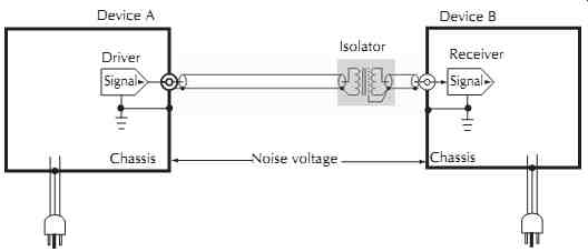
Figure 43. Ground isolator stops noise current in shield of unbalanced cable.
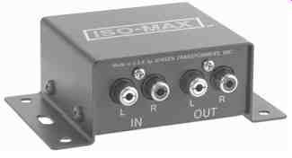
Figure 44. Stereo unbalanced audio isolator. Jensen Transformers,
Inc.
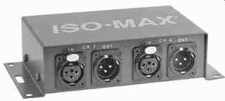
Figure 45. Stereo balanced audio isolator. Jensen Transformers,
Inc.
One safe solution is to break the ground loop by installing a ground isolator in the audio path from preamp to subwoofer as shown in FIG. 48. This isolator could also be installed in the path from TV receiver to preamp, but it is generally best to isolate the longest lines since they are more prone to coupling than shorter ones.
Another safe solution is to break the ground loop by installing a ground isolator in the CATV signal path at the TV receiver as shown in FIG. 49. These RF isolators generally should be installed where the cable connects to the local system, usually at a VCR or TV input. If an RF isolator is used at the input to a splitter, ground loops may still exist between systems served by the splitter outputs since the splitter provides no ground isolation. Although it can be used with a conventional TV or FM antenna, never install an RF isolator between the CATV drop or antenna and its lightning ground connection (see Section 4.1). Isolators will not pass dc operating power to the dish in DBS TV systems.
Since most unbalanced interfaces are made to consumer devices that have two-prong ac plugs, isolating the signal interfaces may leave one or more pieces of equipment with no ground reference whatsoever. This could allow the voltage between an isolator's input and output to reach 50 Vac or more. While this isn't dangerous (leakage current is limited in UL-listed devices), it would require unrealistically high (CMRR over 140 dB) performance by the isolator to reject it! The problem is solved by grounding any floating gear as shown in FIG. 50. This is best done by replacing the two-prong ac plug with a three-prong type and adding a wire (green preferred) wire connected between the safety ground pin of the new ac plug and a chassis ground point.
A screw may be convenient as the chassis ground point. Use an ohmmeter to check for continuity between the screw and the outer contact of an RCA connector, which itself can be used if no other point is available.
Although, in the example above, an added ground at either the preamp or the power amp would suffice, grounding the device with the highest leakage current-usually those devices with the highest ac power consumption rating-will generally result in the lowest noise floor.
__6.3.3 Unbalanced to Balanced and Vice Versa
The reader is referred to Section 11, Section 11.2.2, Audio Transformers, for a more detailed discussion of these applications.
Beware of RCA to XLR adapters! FIG. 51 shows how using this adapter to connect an unbalanced output to a balanced input reduces the interface to an unbalanced one having absolutely no ground noise rejection! The potential noise reduction benefit of the balanced input is completely lost.
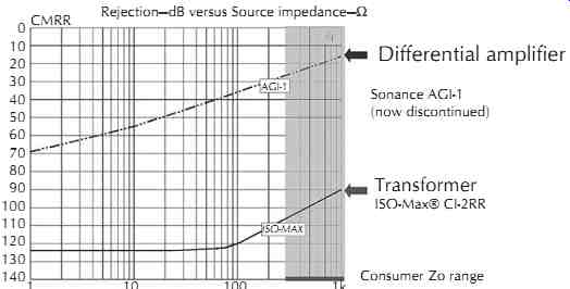
Figure 46. Measured hum rejection versus source impedance, active differential
amplifier versus input transformer isolator.
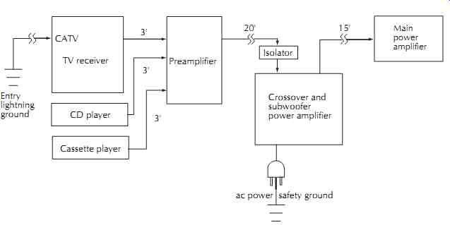
Figure 47. Using an audio ground isolator to break the loop.
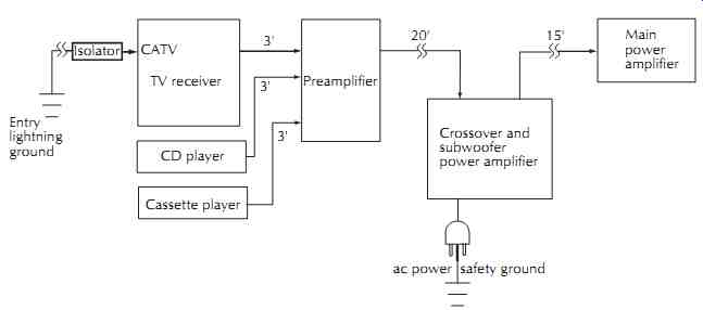
Figure 48. Using a CATV ground isolator to break the loop.
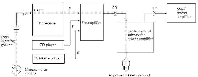
Figure 49. Loop created by two ground connections.
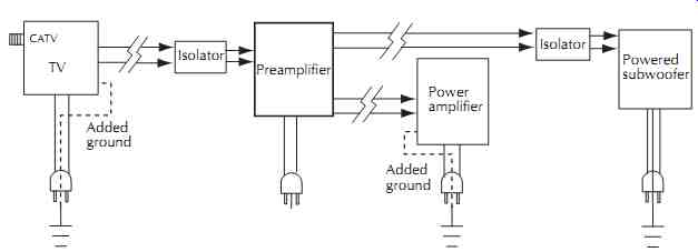
Figure 50. Grounding floating equipment when isolators are installed. From
Jensen AN004.
Proper wiring for this interface, shown in FIG. 52, results in at least 20 dB of noise rejection even if the balanced input is one of typically mediocre performance. The key difference is that, by using shielded twisted pair cable, the ground noise current flows in a separate conductor that is not part of the signal path.
Driving an unbalanced input from a balanced output is not quite as straightforward. Balanced equipment outputs use a wide variety of circuits. Some, such as the one in FIG. 53, might be damaged when one output is grounded. Others, including most popular servo-balanced output stages, can become unstable unless the output is directly grounded at the driver end, which reduces the interface to an unbalanced one with no noise rejection.
Unless a balanced output already utilizes a built-in trans former, using an external ground isolator such as the one shown in FIG. 53 is the only method that will simultaneously avoid weird or damaging behavior and minimize ground noise when used with virtually any output stage.
This approach is used in the ISO-MAX® Pro model PC-2XR pro-to-consumer interface.
__6.3.4 RF Interference
As mentioned earlier, immunity to RF interference or RFI is part of good equipment design. Testing for RFI susceptibility is now mandated in Europe. Unfortunately, much of the equipment available today may still have very poor immunity. Under unfavorable conditions, external measures may be needed to achieve adequate immunity.
For RF interference over about 20 MHz, ferrite clamshell cores shown in FIG. 54, which are easily installed over the outside of a cable, can be very effective. Some typical products are Fair-Rite #0431164281 and Steward #28A0640-0A. In most cases, they work best when placed on the cable at or near the receive end. Often they are more effective if the cable is looped through the core several times.

Figure 51. Incorrect connection of an unbalanced output to a balanced input.

Figure 52. Correct connection of an unbalanced output to a balanced input.

Figure 53. Bullet-proof connection of balanced output to unbalanced input.
Use the shortest possible cable on the RCA side to avoid common-impedance coupling.
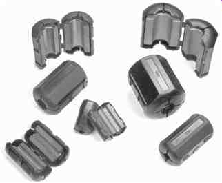
Figure 54. Ferrite cores.
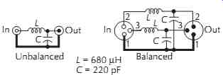
Figure 55. RF interference filters for audio lines.
If this is inadequate, or the frequency is lower (such as AM radio) you may have to add a low-pass--i.e., high-frequency reject-RFI filter on the signal line.
FIG. 55 shows sample 50 kHz cutoff, 12 dB per octave low-pass RFI filters for unbalanced or balanced audio applications. For best performance and audio quality, use NP0 (also called C0G)-type ceramic capacitors keeping leads as short as possible, under ¼ inch preferred. For stubborn AM radio interference, it may help to increase the value of C up to about 1000 pF maximum. The 680 µH inductors are small ferrite core types such as J.W. Miller 78F681J or Mouser 434-22-681. If the only interference is above about 50 MHz, a ferrite bead may be used for L. For the balanced filter, inductors and capacitors should be ±5% tolerance parts or better to maintain impedance balance.
The balanced filter can be used for low-level micro phone lines, but miniature toroidal inductors are recommended to minimize potential hum pickup from stray magnetic fields. These filters, too, are generally most effective at the receive end of the cable.
When possible, the best way to deal with RF inter ference is to control it at its source. FIG. 56 is a schematic of a simple interference filter for solid-state 120 Vac light dimmers rated up to 600 W. It begins attenuating at about 50 kHz and is quite effective at suppressing AM radio interference. It must be installed within a few inches of the dimmer and, unfortunately, the components are large enough that it usually requires an extra-deep or a double knock-out box to accommodate both dimmer and filter. Parts cost is under $10.
A speaker cable can also become an antenna. In a strong RF field, enough voltage can be delivered to the semiconductors in the power amplifier that they become a detector and interference can be heard in the speaker even though the amplifier may be unpowered! More commonly, this problem occurs when the amplifier is powered and RF enters its feedback loop. In either case, the solution depends on the frequency of the interference. Ferrite cores on the cable near the amplifier may
help. In stubborn cases, a 0.1 µF or a 0.22 µF capacitor directly across the output terminals of the amplifier may also be required.
__6.3.5 Signal Quality
Audio transformer design involves a set of complex tradeoffs. The vast majority of available audio trans formers, even when used as directed, fall short of professional performance levels. As Cal Perkins once wrote, "With transformers, you get what you pay for.
Cheap transformers create a host of interface problems, most of which are clearly audible." The frequency response of a high-quality audio trans former is typically ruler flat, ±0.1 dB from 20 Hz to 20 kHz and -3 dB at 0.5 Hz and 100 kHz. The extended low-frequency response is necessary to achieve low phase distortion. The high-frequency response is tailored to fall gradually, following a Bessel function.
This, by definition, eliminates overshoot on square waves and high-frequency response peaking. Dramatic improvements in sonic clarity due to the Bessel filter action are often reported by Jensen customers who add transformers at power amplifier inputs. On the other hand, cheap transformers often have huge ultrasonic peaks in their response that are known to excite particularly ugly intermodulation distortions in even the finest downstream power amplifiers.
Accurate time domain performance, sometimes called transient response, requires low phase distortion to preserve musical timbre and maintain accurate stereo imaging. Phase distortion not only alters sonic quality, it can also have serious system head room effects. Even though it may have a flat frequency response, a device having high phase distortion can increase peak signal amplitudes up to 15 dB. Phase distortion should never be confused with phase shift. Linear phase shift with frequency is simply a benign time delay: only deviations from linear phase or DLP create true phase distortion. This DLP in a high-quality audio transformer is typically under 2° across the entire audio spectrum.
Harmonic and intermodulation distortion in audio transformers is unusually benign in character and cannot fairly be compared to electronic distortion. By their nature, transformers produce the most distortion when driven at high levels at very low frequencies, where the major distortion product is third harmonic. Transformer distortion mechanisms are frequency selective in a way that amplifiers, for example, are not. Electronic nonlinearities tend to produce harmonic distortions that are constant with frequency while high-quality transformer harmonic distortions drop to well under 0.001% at frequencies over a few hundred Hz. Transformers also tend to have remarkably low intermodulation distortion or IMD, to which the ear is particularly sensitive.
Compared to an amplifier of comparable low-frequency harmonic distortion, a transformer typically has only a tenth the IMD. While cheap audio transformers use steel cores producing 1% low-frequency harmonic distortion at any signal level, high-quality transformers use cores of special nickel-iron-molybdenum alloys for vanishingly low distortion.
Of course, noise rejection or CMRR is often the most important property of a ground isolator. As discussed in Section 6.3.1 and Section 11, a trans former requires an internal Faraday shield (not a magnetic or case shield) to maximize CMRR. Most commercial isolators or hum eliminators consist of tiny imported telephone-grade transformers that do not contain such a shield. Beware of products with vague or nonexistent specs! For example, distortion described as under 0.1% is meaningless because frequency, signal level, and source impedance are not specified. The most common problems with inexpensive isolators are marginal noise reduction, loss of deep bass, bass distortion, and poor transient response. Of course, ad copy and specifications of these transformers will put on their best face, withholding the ugly truth! However, isolators using well-designed and properly applied audio trans formers qualify as true high-fidelity devices. They are passive, stable, reliable, and require neither trimming, tweaking, nor excuses.
__6.3.6 Tips for Balanced Interfaces
Be sure all balanced line pairs are twisted. Twisting is what makes a balanced line immune to interference from magnetic fields. This is especially important in low-level microphone cabling. Wiring at terminal or punch-down blocks and XLR connectors is vulnerable because the twisting is opened up, effectively creating a magnetic pickup loop. In very hostile environments, consider starquad cable because it has less susceptibility to magnetic fields. Magnetic coupling is also reduced by separation distance, cables crossing at right angles rather than running parallel, and shielding with magnetic material such as steel EMT conduit.
Pay attention to cable shield grounding. As discussed in Section 5.3, the shield must be grounded at the driven end, it may be grounded at both ends, but never grounded only at the receive end. As a standard practice, grounding at both ends is recommended for two reasons:
1. If the device input has marginal RF suppression, grounding the shield at the input will usually reduce problems,
2. It doesn't require the use of a specially wired cable that might find its way into another system and cause unexpected problems. If special cables are made-to deal with a pin 1 problem, for example-be sure they are clearly marked.
Don't terminate to reduce noise. Nearly every practical audio system should use unterminated audio circuits. This is standard professional audio practice worldwide. While a 600-ohm termination resistor at an input may reduce noise by up to 6 dB or more, depending on the driver output impedance, it will also reduce the signal by the same amount, so nothing is gained. If noise is caused by RF interference, installation of a suitably small capacitor at the input may be much more appropriate.
Use ground isolators to improve noise rejection. As discussed in Section 4.1, common balanced input circuits have generally unpredictable noise rejection in real-world systems. Actual in-system CMRR can be as little as 30 dB when using balanced sources and as little as 10 dB when using unbalanced sources. A quality transformer-based ground isolator can increase the CMRR of even the most mediocre balanced input to over 100 dB.
Beware of the pin 1 problem. As much as 50% of commercial equipment, some from respected manufacturers, has this designed-in problem. If disconnecting the shield at an input or output reduces a hum problem, the device at one or the other end of that cable may be the culprit. See Section 5.3 for test methods. Loose connector-mounting hardware is a major cause of pin 1 problems. Never overlook the obvious!
__6.3.7 Tips for Unbalanced Interfaces
Keep cables as short as possible. Longer cables in crease the coupling impedance. Serious noise coupling is nearly certain with 50 ft or 100 ft cables. Even much shorter cables can produce severe problems if there are multiple grounds. And never coil excess cable length.
Use cables with heavy gauge shields. Cables with shields of foil and thin drain wires increase the common-impedance coupling. Use cables with heavy braided copper shields, especially for long cables. See Section 7.4 for a recommended high-performance cable. The only property of cable that has any significant effect on audio-frequency noise coupling is shield resistance, which can be measured with an ordinary ohmmeter.
Bundle signal cables. All signal cables between any two boxes should be bundled. For example, if the L and R cables of a stereo pair are separated, nearby ac magnetic fields will induce a current in the loop formed by the two shields, causing hum in both signals. Like wise, all ac power cords should be bundled. This will tend to average and cancel the magnetic and electro static fields they radiate. In general, keeping signal bundles and power bundles separated will reduce coupling.
Maintain good connections. Connectors left undisturbed for long periods can oxidize and develop high contact resistance. Hum or other interference that changes when the connector is wiggled indicates a poor contact. Use a good commercial contact fluid and/or gold-plated connectors to help prevent such problems.
Don't add unnecessary grounds! Additional grounding almost always increases circulating noise currents rather than reducing them. As emphasized earlier, never disconnect or defeat the purpose of safety or lightning ground connections to solve a noise problem-the practice is both illegal and very dangerous!
Use ground isolators at problem interfaces. Transformer-based isolators magnetically couple the signal while completely breaking the noise current path through the cable and connectors. This eliminates common-impedance coupling and can improve immunity to RF interference as well.
Predict and solve problems before an installation. For systems that consist mostly of devices with two-prong power cords, some very simple multimeter measurements on each system device and cable makes it possible to actually predict hum levels and identify the problem interfaces before a system is installed.
__7 Alternative Treatments and Pseudoscience
The audio industry, especially the high-end segment, abounds with misinformation and myth. Science, evidence, and common sense are often discarded in favor of mysticism, marketing hype, and huge profits.
Just remember that the laws of physics have not changed! See FIG. 57.
__7.1 Grounding from Technical to Bizarre
In most commercial buildings, the ac outlets on any branch circuit are saddle grounded or SG-types mounted in metallic J-boxes. Since SG outlets connect their safety ground terminals to the J-box, the safety ground network may now be in electrical contact with plumbing, air ducts, or structural building steel. This allows coupling of noisy currents from other loads- which might include air conditioning, elevators, and other devices-into the ground used by the sound system. In a scheme called technical or isolated grounding, safety grounding is not provided by the J-box and conduit but by a separate insulated green wire that must be routed back to the electrical panel alongside the white and black circuit conductors to keep inductance low. The technique uses special insulated ground or IG outlet-marked with a green triangle and some times orange in color-which intentionally insulates the green safety ground terminal from the outlet mounting yoke or saddle. The intent of the scheme is to isolate safety ground from conduit. Noise reduction is some times further improved by wiring each outlet as a home run back to the electrical panel or subpanel, making each outlet essentially a separate branch circuit. This technique is covered by NEC Article 250-74 and its exceptions. In many cases, simply adding a new branch circuit can be just as effective yet far less expensive than implementing a technical ground system.
Many people, believing that the earth simply absorbs noise, have a strong urge to install multiple earth ground rods to fix noise. This is desperation-mode thinking.
Code allows extra ground rods, but only if they are bonded to an existing properly implemented safety ground system. Code does not allow them to be used as a substitute soil resistance is simply too high and unstable to be relied on to divert fault currents.
Equipment grounding via the standard power cord safety ground is logical, easy to implement, and safe.
It's highly recommended for all systems and is the only practical method for portable or often reconfigured systems.
__7.2 Power-Line Isolation, Filtering, and Balancing
Most sound systems use utility ac power. If it is disconnected, of course, all hum and noise disappears.
This often leads to the odd conclusion that the noise is brought in with the power and that the utility company or the building wiring is to blame. Devices claiming to cleanse and purify ac power have great intuitive appeal and are often applied without hesitation or much thought. A far more effective approach is to locate, and safely eliminate, ground loops that cause coupling of noise into the signal. This solves the real problem. In reality, when system designs are correct, special power treatment is rarely necessary. Treating the power line to rid it of noise is analogous to repaving all the highways to fix the rough ride of a car. It's much more sensible to correct the cause of the coupling by replacing the shock absorbers!

Figure 57. Officer Einstein of the Physics Police. Coil-Craft.
First, when any cord-connected line filter, conditioner, or isolation transformer is used, Code requires that the device as well as its load still be connected to safety ground as shown in FIG. 58. Cord-connected isolation transformers cannot be treated as separately derived sources unless they are permanently wired into the power distribution system per Code requirements.
Sometimes makers of isolation transformers have been known to recommend grounding the shield and output to a separate ground rod. Not only does this violate Code, but the long wire to the remote ground renders the shield ineffective at high frequencies. It is a sobering fact that, while a device may control interference with respect to its own ground reference, it may have little or no effect at the equipment ground. Because all these cord-connected devices divert additional 60 Hz and high-frequency noise currents into the safety ground system, they often aggravate the very problem they claim to solve. External, cord-connected filters, or those built into outlet strips, can serve to band-aid badly designed equipment. As shown in FIG. 24 (Section 4.2), some equipment is sensitive because common-mode power line disturbances, especially at high frequencies, have essentially been invited in to invade the signal circuitry! Second, the advertised noise attenuation figures for virtually all these power line devices are obtained in a most unrealistic way. Measurements are made with all equipment (generator, detector, and device under test) mounted to a large metal ground plane. Although the resulting specs are impressive, they simply don't apply to performance in real-world systems where ground connections are made with mere wires or conduit.
However, these devices can be very effective when installed at the power service entrance or a subpanel, where all system safety grounds are bonded to a common reference point. For thorough, accurate information about separately derived power distribution and its application to equipment racks, the author highly recommends reference.
Balanced power, more properly symmetrical power, is another seductively appealing concept shown in FIG. 59. If we assumed that each system box had neatly matched parasitic capacitances from each leg of the power line to its chassis ground, the resulting noise current flow into the safety ground system would be zero, the inter-chassis voltage would be zero, and the resulting system noise due to these currents would simply disappear! For example, if C1 and C2 had equal capacitance and the ac voltages across them were equal magnitude but opposite polarity, the net leakage current would indeed be zero. However, for the overwhelming majority of equipment, these capacitances are not equal or even close. In many cases, one is several times as large as the other-it's just a reality of power trans former construction. Even if the equipment involved has two-prong ac power connections, actual noise reduction will likely be less than 10 dB and rarely exceed 15 dB.
And it's unlikely that equipment manufacturers will ever pay the premium to match transformer parasitic capacitances or use precision capacitors in power line EMI filters. If the equipment involved has three-prong (grounding) ac power connections, the leakage current reduction, if any, provided by symmetrical power will pale by comparison to the magnetically induced voltage differences described in Section 3.4. In fact, many of the benefits attributed to symmetrical power may result from simply plugging all system equipment into the same outlet strip or dedicated branch circuit-which is always a good idea.
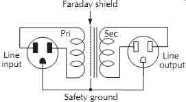
Figure 58. Power isolation transformer. Faraday shield; Safety ground; Line
input Pri Sec Line output
A GFCI (ground-fault circuit interrupter) works by sensing the difference in current between the hot and neutral connections at an outlet. This difference represents current from the hot conductor that is not returning via neutral. The worst-case scenario assumes that the missing current is flowing through a person.
When the difference current reaches 4-7 mA- producing a very unpleasant but non-life-threatening shock-an internal circuit breaker removes power in a fraction of a second. Some power conditioners feature a ground lift switch, touted to eliminate ground loop problems, at their outputs. The National Electrical Code requires that all balanced power units have GFCI-protected outputs (among other restrictions on the use of balanced power). Although safe, ground lifting makes a GFCI-protected circuit prone to nuisance trips.
For example, consider the system hook-up shown in FIG. 60.

Figure 59. Balanced power hopes to cancel ground currents.
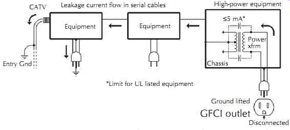
Figure 60. Common scenario to produce nuisance trips of GFCI in power conditioner.
For equipment having a grounding (three-conductor) power cord, UL listing requires that its leakage current be no more than 5 mA. Normally, this current would flow through the safety ground path back to neutral and would not trip a GFCI that has an intact safety ground connection. However, if the safety ground is lifted and the equipment is connected to other system equipment via signal cables, the leakage current will flow in these cables to reach ground, and ultimately neutral. Because the current is not returning via the equipment's own power cord, the GFCI considers it hazardous and may trip, since 5 mA is within its trip range. If multiple pieces of equipment are plugged into a single GFCI-protected circuit, the cumulative leakage currents can easily become high enough to trip the GFCI. This problem severely limits the ability of the GFCI/ ground-lift combo to solve ground loop problems--even when balanced power partially cancels leakage currents.
__7.3 Surge Protection
Haphazard placement of common surge protectors can actually result in damage to interface hardware if the devices are powered from different branch circuits.
As shown in FIG. 61, very high voltages can occur should there be an actual surge. The example shows a common protective device using three metal-oxide varistors, usually called MOVs, which limit voltage to about 600 Vpeak under very high-current surge conditions.
For protection against lightning-induced power line surges, this author strongly recommends that MOV protective devices, if used at all, be installed only at the main service entry. At subpanels or on branch circuits to protect individual groups of equipment, use series-mode suppressors, such as those by Surge-X, that do not dump surge energy into the safety ground system, creating noise and dangerous voltage differences.
__7.4 Exotic Audio Cables
In the broadest general meaning of the word, every cable is a transmission line. However, the behavior of audio cables less than a few thousand feet long can be fully and rigorously described without transmission line theory. But this theory is often used as a starting point for pseudotechnical arguments that defy all known laws of physics and culminate in outrageous performance claims for audio cables. By some estimates, these specialty cables are now about a $200 million per year business.
Beware of cable mysticism! There is nothing unexplainable about audible differences among cables. For example, it is well known that the physical design of an unbalanced cable affects common-impedance coupling at ultrasonic and radio frequencies. Even very low levels of this interference can cause audible spectral contamination in downstream amplifiers.
Of course, the real solution is to prevent common-impedance coupling in the first place with a ground isolator, instead of agonizing over which exotic cable makes the most pleasing subtle improvement. Expensive and exotic cables, even if double or triple shielded, made of 100% pure unobtainium, and hand braided by Peruvian virgins, will have NO significant effect on hum and buzz problems! As discussed in Section 5.4, shielding is usually a trivial issue compared to common-impedance coupling in unbalanced interfaces.
It's interesting to note that some designer cables selling for $500/meter pair have no overall shield at all-ground and signal wires are simply woven together.
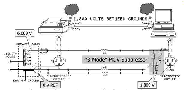
Figure 61. Surge protection can actually invite equipment damage.
Some exotic audio cables have very high capacitance and can seriously degrade high-frequency response, especially if cables are long and/or a consumer device drives it. For demanding high-performance applications, consider a low-capacitance, low-shield-resistance cable such as Belden #8241F. Its 17 pF/ft capacitance allows driving a 200 ft run from a typical 1 k: consumer output while maintaining a -3 dB bandwidth of 50 kHz.
And its low 2.6 m:/ft shield resistance, equivalent to #14 gauge wire, minimizes common-impedance coupling. It's also quite flexible and available in many colors.
Suggested Reading:
Henry Ott, Noise Reduction Techniques in Electronic Systems, Second Edition, John Wiley & Sons, 1988.
Ralph Morrison and Warren Lewis, Grounding and Shielding in Facilities, John Wiley & Sons, 1990.
Ralph Morrison, Grounding and Shielding Techniques in Instrumentation, Third Edition, John Wiley & Sons, 1986.